EP2516092B1 - Vefahren und vorrichtung zur herstellung von kegelgetrieben - Google Patents
Vefahren und vorrichtung zur herstellung von kegelgetrieben Download PDFInfo
- Publication number
- EP2516092B1 EP2516092B1 EP10799224.0A EP10799224A EP2516092B1 EP 2516092 B1 EP2516092 B1 EP 2516092B1 EP 10799224 A EP10799224 A EP 10799224A EP 2516092 B1 EP2516092 B1 EP 2516092B1
- Authority
- EP
- European Patent Office
- Prior art keywords
- tool
- spindle
- workpiece
- axis
- machine
- Prior art date
- Legal status (The legal status is an assumption and is not a legal conclusion. Google has not performed a legal analysis and makes no representation as to the accuracy of the status listed.)
- Not-in-force
Links
- 238000000034 method Methods 0.000 title claims description 18
- 238000004519 manufacturing process Methods 0.000 title claims description 4
- 238000007514 turning Methods 0.000 claims description 73
- 238000005520 cutting process Methods 0.000 claims description 56
- 238000003754 machining Methods 0.000 claims description 20
- 239000002184 metal Substances 0.000 claims 8
- 229910052751 metal Inorganic materials 0.000 claims 8
- 230000033001 locomotion Effects 0.000 description 14
- 238000005242 forging Methods 0.000 description 13
- 238000003801 milling Methods 0.000 description 6
- 238000005553 drilling Methods 0.000 description 5
- 238000010276 construction Methods 0.000 description 3
- 238000013461 design Methods 0.000 description 3
- 239000000463 material Substances 0.000 description 3
- 238000010079 rubber tapping Methods 0.000 description 3
- 230000001154 acute effect Effects 0.000 description 2
- 238000012986 modification Methods 0.000 description 2
- 230000004048 modification Effects 0.000 description 2
- 238000002360 preparation method Methods 0.000 description 2
- 238000007790 scraping Methods 0.000 description 2
- 230000015572 biosynthetic process Effects 0.000 description 1
- 230000003292 diminished effect Effects 0.000 description 1
- 238000012545 processing Methods 0.000 description 1
- 239000007787 solid Substances 0.000 description 1
- 238000012546 transfer Methods 0.000 description 1
- 238000004804 winding Methods 0.000 description 1
Images






Classifications
-
- B—PERFORMING OPERATIONS; TRANSPORTING
- B23—MACHINE TOOLS; METAL-WORKING NOT OTHERWISE PROVIDED FOR
- B23F—MAKING GEARS OR TOOTHED RACKS
- B23F17/00—Special methods or machines for making gear teeth, not covered by the preceding groups
- B23F17/006—Special methods or machines for making gear teeth, not covered by the preceding groups using different machines or machining operations
-
- B—PERFORMING OPERATIONS; TRANSPORTING
- B23—MACHINE TOOLS; METAL-WORKING NOT OTHERWISE PROVIDED FOR
- B23F—MAKING GEARS OR TOOTHED RACKS
- B23F19/00—Finishing gear teeth by other tools than those used for manufacturing gear teeth
- B23F19/10—Chamfering the end edges of gear teeth
-
- B—PERFORMING OPERATIONS; TRANSPORTING
- B23—MACHINE TOOLS; METAL-WORKING NOT OTHERWISE PROVIDED FOR
- B23F—MAKING GEARS OR TOOTHED RACKS
- B23F23/00—Accessories or equipment combined with or arranged in, or specially designed to form part of, gear-cutting machines
- B23F23/12—Other devices, e.g. tool holders; Checking devices for controlling workpieces in machines for manufacturing gear teeth
- B23F23/1237—Tool holders
-
- B—PERFORMING OPERATIONS; TRANSPORTING
- B23—MACHINE TOOLS; METAL-WORKING NOT OTHERWISE PROVIDED FOR
- B23F—MAKING GEARS OR TOOTHED RACKS
- B23F9/00—Making gears having teeth curved in their longitudinal direction
- B23F9/08—Making gears having teeth curved in their longitudinal direction by milling, e.g. with helicoidal hob
- B23F9/10—Making gears having teeth curved in their longitudinal direction by milling, e.g. with helicoidal hob with a face-mill
-
- Y—GENERAL TAGGING OF NEW TECHNOLOGICAL DEVELOPMENTS; GENERAL TAGGING OF CROSS-SECTIONAL TECHNOLOGIES SPANNING OVER SEVERAL SECTIONS OF THE IPC; TECHNICAL SUBJECTS COVERED BY FORMER USPC CROSS-REFERENCE ART COLLECTIONS [XRACs] AND DIGESTS
- Y10—TECHNICAL SUBJECTS COVERED BY FORMER USPC
- Y10T—TECHNICAL SUBJECTS COVERED BY FORMER US CLASSIFICATION
- Y10T29/00—Metal working
- Y10T29/49—Method of mechanical manufacture
- Y10T29/49462—Gear making
- Y10T29/49467—Gear shaping
- Y10T29/49476—Gear tooth cutting
-
- Y—GENERAL TAGGING OF NEW TECHNOLOGICAL DEVELOPMENTS; GENERAL TAGGING OF CROSS-SECTIONAL TECHNOLOGIES SPANNING OVER SEVERAL SECTIONS OF THE IPC; TECHNICAL SUBJECTS COVERED BY FORMER USPC CROSS-REFERENCE ART COLLECTIONS [XRACs] AND DIGESTS
- Y10—TECHNICAL SUBJECTS COVERED BY FORMER USPC
- Y10T—TECHNICAL SUBJECTS COVERED BY FORMER US CLASSIFICATION
- Y10T29/00—Metal working
- Y10T29/51—Plural diverse manufacturing apparatus including means for metal shaping or assembling
- Y10T29/5104—Type of machine
- Y10T29/5109—Lathe
- Y10T29/5114—Lathe and tool
-
- Y—GENERAL TAGGING OF NEW TECHNOLOGICAL DEVELOPMENTS; GENERAL TAGGING OF CROSS-SECTIONAL TECHNOLOGIES SPANNING OVER SEVERAL SECTIONS OF THE IPC; TECHNICAL SUBJECTS COVERED BY FORMER USPC CROSS-REFERENCE ART COLLECTIONS [XRACs] AND DIGESTS
- Y10—TECHNICAL SUBJECTS COVERED BY FORMER USPC
- Y10T—TECHNICAL SUBJECTS COVERED BY FORMER US CLASSIFICATION
- Y10T29/00—Metal working
- Y10T29/51—Plural diverse manufacturing apparatus including means for metal shaping or assembling
- Y10T29/5176—Plural diverse manufacturing apparatus including means for metal shaping or assembling including machining means
-
- Y—GENERAL TAGGING OF NEW TECHNOLOGICAL DEVELOPMENTS; GENERAL TAGGING OF CROSS-SECTIONAL TECHNOLOGIES SPANNING OVER SEVERAL SECTIONS OF THE IPC; TECHNICAL SUBJECTS COVERED BY FORMER USPC CROSS-REFERENCE ART COLLECTIONS [XRACs] AND DIGESTS
- Y10—TECHNICAL SUBJECTS COVERED BY FORMER USPC
- Y10T—TECHNICAL SUBJECTS COVERED BY FORMER US CLASSIFICATION
- Y10T409/00—Gear cutting, milling, or planing
- Y10T409/10—Gear cutting
- Y10T409/101113—Gear chamfering or deburring
- Y10T409/101272—Using relatively reciprocating or oscillating cutter
-
- Y—GENERAL TAGGING OF NEW TECHNOLOGICAL DEVELOPMENTS; GENERAL TAGGING OF CROSS-SECTIONAL TECHNOLOGIES SPANNING OVER SEVERAL SECTIONS OF THE IPC; TECHNICAL SUBJECTS COVERED BY FORMER USPC CROSS-REFERENCE ART COLLECTIONS [XRACs] AND DIGESTS
- Y10—TECHNICAL SUBJECTS COVERED BY FORMER USPC
- Y10T—TECHNICAL SUBJECTS COVERED BY FORMER US CLASSIFICATION
- Y10T409/00—Gear cutting, milling, or planing
- Y10T409/10—Gear cutting
- Y10T409/101431—Gear tooth shape generating
-
- Y—GENERAL TAGGING OF NEW TECHNOLOGICAL DEVELOPMENTS; GENERAL TAGGING OF CROSS-SECTIONAL TECHNOLOGIES SPANNING OVER SEVERAL SECTIONS OF THE IPC; TECHNICAL SUBJECTS COVERED BY FORMER USPC CROSS-REFERENCE ART COLLECTIONS [XRACs] AND DIGESTS
- Y10—TECHNICAL SUBJECTS COVERED BY FORMER USPC
- Y10T—TECHNICAL SUBJECTS COVERED BY FORMER US CLASSIFICATION
- Y10T409/00—Gear cutting, milling, or planing
- Y10T409/10—Gear cutting
- Y10T409/101431—Gear tooth shape generating
- Y10T409/103816—Milling with radial faced tool
- Y10T409/103975—Process
-
- Y—GENERAL TAGGING OF NEW TECHNOLOGICAL DEVELOPMENTS; GENERAL TAGGING OF CROSS-SECTIONAL TECHNOLOGIES SPANNING OVER SEVERAL SECTIONS OF THE IPC; TECHNICAL SUBJECTS COVERED BY FORMER USPC CROSS-REFERENCE ART COLLECTIONS [XRACs] AND DIGESTS
- Y10—TECHNICAL SUBJECTS COVERED BY FORMER USPC
- Y10T—TECHNICAL SUBJECTS COVERED BY FORMER US CLASSIFICATION
- Y10T409/00—Gear cutting, milling, or planing
- Y10T409/10—Gear cutting
- Y10T409/101431—Gear tooth shape generating
- Y10T409/103816—Milling with radial faced tool
- Y10T409/104134—Adapted to cut bevel gear
Definitions
- the present invention is directed to the production of bevel gears and in particular to the formation of a final dimensioned gear blank and a cut gear on a gear cutting machine in a single chucking.
- Bevel gears blanks i.e. ring gear and pinion
- ring gear blanks are usually manufactured from forgings.
- the forgings include an amount of excess stock material so as to allow for machining in order to clean up the blank surface and achieve the correct blank dimensions.
- Gear blank forgings are often dimensioned such that they can be used for all members of a part (i.e. gear) family.
- the stock allowance can be several millimeters.
- the pinion shank design is usually identical for all different members of the part family and only the pinion head (diameter, face angle etc.) varies among family members.
- the ring gears members of part families usually have an identical bore and back face geometry (e.g. bolt hole pattern, tapping, inner and outer diameter of the back face) while the front inside surface, front face and front outside surfaces usually vary among family members.
- Pinion blanks are usually turned in one chucking (i.e. positioning and securing a workpiece for machining on a machine tool) between centers while ring gear blanks are usually turned in at least two chuckings.
- Smaller ring gears are mostly turned in two-spindle CNC lathes (i.e. two chuckings) while larger ring gears (e.g. diameter 400mm and above) are often turned in two or even three separate machines (i.e. two or more chuckings).
- the gear blank is usually transferred to a bevel gear cutting machine where the teeth of the gear are formed.
- US 2008/0152446 to Müller et al. teach a device for performing green machining of a bevel gear blank (e.g. drilling, turning, milling, etc.) at a pre-machining station followed by transfer of the gear blank to an adjacent machining station for cutting the bevel gear teeth.
- a bevel gear blank e.g. drilling, turning, milling, etc.
- US 2008/0213055 to Ozdyk et al. teach a device for the soft machining of bevel gears comprising a lathe arrangement having a tool base and a tool housing both of which are translatable at least horizontally in the X and Y directions on the base of the lathe.
- the tool base comprises a tool carriage and a tool holder that is rotatable about an axis B2 with at least one tool (e.g. turning, drilling, etc.) being positioned on the tool holder for machining a gear blank.
- At least one of the tools on the tool holder is separately rotatable about another axis B4 arranged generally parallel to the tool holder axis B2.
- the tool housing includes a milling head comprising a gear cutting tool which is rotatable about an axis B3.
- ring gear and pinion blanks would only have to undergo a single chucking in a CNC lathe, preferably to machine those surfaces common to all members of the part (gear) family (no machining of the surfaces which vary within the part family). In the case of part families, the inventory of blanks could be minimized since subsequent front turning operations could be utilized to produce a blank of a desired size.
- the present invention is directed to a method and apparatus wherein the front machining of a gear blank are carried out on a CNC bevel gear generator utilizing the motions available in such machines with minimal modifications to the existing machine tool.
- the invention provides a machine according to claim 1.
- the preamble of claim 1 is based on US 6,669,415 .
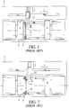
- Figure 1 shows a CNC lathe 2 having two spindles 4, 6 with a ring gear forging 8 clamped in the left side chuck 10 on the left spindle 4.
- the universal tool holder 12 can move at least in the two directions (X, Z) given by the drawing plane.
- the left insert 14 is turning the inside bore 16 of the forging 8.
- Figure 2 shows turning the back face 18 of the forging 8 with a different cutting edge of the left insert 14.
- the left insert 14 is turning the back outside diameter 20 of the forging 8.
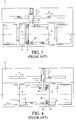
- the ring gear forging 8 has been transferred to and chucked in the right side chuck 22 on the right spindle 6.
- the universal tool holder 12 is repositioned via X, Z motions and uses the right upper insert 24 to turn the front inside surface 26 (front angle) of the ring gear blank 8.
- the lower right insert 28 is turning the front face 30 (face angle) of the ring gear blank 8.
- the lower right insert 28 is turning the front outside surface 32 (back angle) of the ring gear blank 8.
- a "first chucking" for ring gears is considered to comprise those machining operations performed that produce bore and back face geometry on all part family members (e.g. turn the bore 16, back face 18, back outside diameter 20 and conduct drilling and tapping operations) as exemplified in Figures 1-3 (drilling and tapping not shown but may be performed on the same or a different machine).
- the first chucking operations are the same for all members of the part family as earlier discussed.
- the remaining operations i.e. front machining operations
- that usually produce different finished geometries on part family members are considered to be “second chucking" operations as exemplified in Figures 4-6 .
- a "first chucking" is considered to comprise those machining operations performed that produce the same geometry (e.g. shank geometry) on all part family members.
- the remaining "front machining” operations that produce different finished geometries on pinion family members are considered to be “second chucking” operations.
- FIG. 7 The present invention is shown in Figure 7 wherein a ring gear blank 40 which has been partially machined (e.g. turned) in a "first chucking" ( Figures 1 through 3 ) on a lathe or machining center is clamped for rotation about axis A on the work spindle 42 of a multi-axis CNC bevel gear generating machine (a six-axis CNC bevel gear generating machine 44 as shown in Figure 15 ).
- Such machines are known and are described, for example, in U.S. Patent Nos. 6,669,415 ; 6,712,566 ; 4,981,402 and 5,961,260 .
- the gear blank 40 is held (i.e. chucked) via its reference bore 46 by an expanding-type arbor 48.
- a tool holder 50 which is connected rigidly with a non-rotatable tool (e.g. cutter) spindle housing 52 ( Figure 8 ) allows for relative movements between tool holder 50 and the workpiece 40 in the same manner as relative movements between the workpiece 40 and tool 54 ( Figure 8 ).
- the tool holder 50 may have one or more inserts but preferably comprises two inserts 56, 58.
- the upper insert 56 is turning the front outside surface 60 (back angle) of the ring gear blank 40.
- the relative movement of the tool holder 50 versus the blank 40 is in the direction of the arrow.
- Figure 8 shows a 6-axis bevel gear cutting machine 44 which includes the tool holder 50 for a turning operation (as in Figure 7 ) but with additional components of the bevel gear cutting machine.
- the upper insert 56 of the tool holder 50 is turning the front outside surface 60 (back angle) of the ring gear blank 40.
- Tool 54 is rotatable about tool axis C via tool spindle 55 residing within the tool spindle housing 52.
- the tool 54 comprising cutter head 62 and cutting blades 64 for the tooth cutting operation, is inactive during the turning operation.
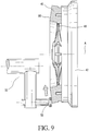
- Figure 9 shows the turning of the front surface 66 (face angle) of the ring gear blank 40 with another cutting edge of the upper insert 56.
- the relative movement of the tool 56 holder versus the gear blank 40 is indicated by the arrow.
- the bevel gear face cutter 54 is positioned relative to the gear blank 40 to perform the tooth cutting operation as seen in Figure 11 .
- the rotation of the ring gear blank 40 i.e. counter clockwise
- tooth cutting e.g. continuous cutting method, face hobbing
- the direction of the cutter rotation is also indicated in Figure 11 .
- the tool holder 50 and its inserts 56, 58 are inactive and are located clear of the ring gear blank and all machine components.
- the ring gear blank 40 After cutting ( Figure 11 ) the ring gear blank 40 has become a gear 70 comprising teeth 72 as seen in Figure 12 .
- a burr 74 is formed on the outside end of each tooth 72.
- the end of the convex tooth flank forms an obtuse angle with the outside surface of the ring gear 70 and the end of the concave flank forms an acute angle with the outside surface of the ring gear 70.
- the burr 74 is generally formed only on the outside (heel) end of the concave flank, caused by the acute angle.
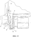
- the tool holder 50 moves to the position shown in Figures 12 or 13 and the insert 56 is able to remove the burr 74 caused by the tooth cutting with the rotational direction of the ring gear 70 as indicated in Figures 12 or 13 .
- the opposite rotational direction of the ring gear can be used if the insert has also cutting edges on the opposite side.
- the tool holder 50 with the insert 56 can move quickly in one position (just contacting the outside diameter of the ring gear) in order to scrape off the burr 74 preferably with the long side of the insert 56 (not using one of the pointed corners) thereby scraping from the tooth slot in the direction of the concave flank.
- the tool holder 50 with insert 56 may move in the position shown in Figure 7 thereby repeating turning of the front outside surface 60 in the area of the tooth depth.
- the cutting edge orientation and the hand of rotation of the ring gear should provide a cutting action from the tooth slot towards the concave flank of the tooth.
- the cutting edge has an offset extending generally perpendicular to the drawing plane. In case the direction of part rotation is opposite during deburring than during cutting (where inserts with cutting edges on top and bottom are utilized), the offset has to be changed in the opposite direction in order to create again the proper relief angle for deburring.
- Figures 14(a) and 14(b) show elements of tool holder 50 comprising an exchangeable front part 80 having a primary arm 81 with a spline 82 and bolt 84 for connection to a stationary back post 86.
- Front part 80 additionally includes spacing arm 88 and insert arm 90 both of which may be interchangeable for various sizes (i.e. lengths).
- the back post 86 is preferably rigidly connected to the bevel gear cutting machine 44 such as in or adjacent to the tool spindle housing 52 ( Figure 15 ).
- Figure 14(b) shows a front view onto the spline 82.
- the interchangeability allows a wide range of different parts (size and design) to be accommodated. It also enables the proper size of tool holder 50 to be provided in order to avoid interference with machine components.
- the tool holder 50 may be of a one-piece design or may consist of several parts (e.g. 81, 88 and 90). Those parts can be combined in a building block scheme by the user of the equipment or especially designed by
- tool holder 50 may be advanced or retracted (e.g. telescopically) with respect to the gear cutting machine 44 via hydraulic, pneumatic, electric, manual or other means.
- Tool holder 50 may be capable of swinging from a "park" position to a turning position around a pivot axis or use a trapezoidal or other linkage to move between a park and operating position.
- primary arm 81 and insert arm 90 are each oriented parallel to tool axis C while spacing arm 88 is preferably oriented perpendicular to the orientation of primary arm 81 and insert arm 90. It is also possible to attach a plurality of tool holders to a gear cutting machine which may comprise a combination of different rigid, retractable and/or swing type tool holders.
- Figure 15 represents a three-dimensional view of a six-axis free form bevel gear cutting machine with three rectilinear axes X, Y and Z as well as thee rotational axis A (work spindle rotation), B (tool spindle pivot axis) and C (tool axis rotation). Attached to the cutter spindle housing is the tool holder post 50. This arrangement enables utilization of four axes of the machine (X, Y, Z and B) to position the tool holder 50 relative to the gear blank 40 (or cut gear 70) for the turning (or deburring) operation. Axis A (work rotation) is also utilized in order to rotate the gear blank (or gear) for the turning (or deburring) operations.
- the freedoms, accuracy and stiffness of a bevel gear generator are generally greater than CNC lathes designated to turn the same size parts.
- the chucking on a bevel gear generator replaces the second chucking (and handling) on a lathe or machining center, and, the handling and chucking on the bevel gear generator with only one chucking on the bevel gear generator.
- Chucking on a bevel gear generator is very accurate, usually accomplished with a high precision disk spring expander, which will assure minimal run out between the ring gear bore and back face (formed in first chucking in a lathe) and the face cone.
- the run out quality is not always given with respect to lathes because the second chucking is generally done with a three jaw chuck which does not guarantee high run out quality.
- the bevel cutting machine 44 executes two or more connected part programs.
- the turning and/or deburring programs may receive information from the part drawing (ring gear or pinion) as well as information about the tool holder (dimensions of combined elements) as input data.
- a gaging of the turning tool can be required. The gaging is possible utilizing special gaging equipment (off the machine) or in the machine using gage bars, gage disks or even a master blank.
- a machining process may be performed by the following steps:
- the gear blank 40 is loaded and chucked on the work spindle 42.
- the machine axes X, Y, Z and B move from their load position, preferably in a rapid move, to a position where the upper insert 56 with its left corner is behind the front outside surface 60 (i.e. to the right of corner 71 in Figure 7 ).
- the work spindle 42 starts rotating at a predetermined speed (RPM) in order to archive sufficient surface speed for the turning operation.
- the machine axes X and Z move simultaneously in a linear interpolation relationship whereby the left corner of the upper insert 56 removes chips along the outside surface 60.
- the turning motion is carried out with a feed motion that provides a common turning feed rate to a position which over travels the outside surface 60 slightly in order to finish turning the outside surface 60 and to position the right corner of the upper insert 56 in the starting position for turning, if desired, a facet at the corner 69 between outer surface 60 and front surface 66.
- the machine axes X and Z move simultaneously in a linear interpolating relationship (while the right corner of the upper insert 56 is turning a facet between outside surface 60 and front face 66) to a position that is the staring point for the front surface 66 turning (with the same right corner of the upper insert 56).
- the machine axes X and Z move simultaneously in a linear interpolating relationship so that the right corner of the upper insert 56 turns the front surface 66 of the gear blank 40. Because of the diameter change during this turning step, the spindle RPM may be changed between the beginning and the end of the front face turning in order to achieve an acceptable turning surface speed. It is also possible to change the RPM constantly in a linear relationship to the actual turning diameter in order to achieve an optimal turning surface speed.
- the relief angle between the insert 56 and the conical front face 66 is different then it was during turning of the outside surface 60.
- a different offset in a direction perpendicular to the drawing plane (Y-direction of gear cutting machine) can be used to reestablish a sufficient relief angle.
- the offset change can be accomplished during the facet turning as described above. This requires a Y-axis value which simultaneously changes, in an interpolating mode together with the X- and Z-axes while the facet is being turned. While the cutting corner of the insert 56 moves from the outside diameter to the inside diameter and turns the front face 66, the offset Y may simultaneously change in order to maintain an optimal cutting insert relief angle.
- the turning of this step requires an over travel because the following turning step requires a change of the active cutting edge and insert.
- the machine axes then move, preferably in a fast motion, to a new X, Y and Z position (the Y position provides optimal relief angle of the insert during the turning operation of the facet and the front inside surface.
- the right corner of the lower insert 58 may now be used to produce a facet at the corner 67 between the front face 66 and the front inside surface 68 of the gear blank 40.
- the machine axis X and Z move simultaneously in an interpolating mode to the end position of the facet (the Y axis may also change to maintain an optimal insert relief angle).
- the work spindle RPM is selected to provide optimal turning surface speed.
- the machine axes X and Z then move simultaneously in a linear interpolating relationship whereby the right corner of the lower insert 58 is utilized to turn the front inside surface 68 of the gear blank 40. Because of the diameter change during this turning step, the spindle RPM may be adjusted to a speed between the beginning and the end of the front inside turning to achieve an acceptable turning surface speed. It is also possible to change the RPM constantly in a linear relationship to the actual turning diameter in order to achieve an optimal turning surface speed.
- the machine axes X, Y, Z and B are then moved from their front inside 68 turning end position, preferably in a rapid move, to an indexing position. This is the position that presents the cutter 54 to the gear blank 40 at the beginning of the tooth cutting process.
- the gear blank 40 is cut with a face hobbing cutter head 54 in a non-generating continuously indexing operation ( Figure 11 ) to produce a gear 70 ( Figure 12 ).
- This requires the cutter head 54 and the gear blank 40 to rotate in the directions as shown by the respective arrows in Figure 11 .
- the cutting in this example requires a feed motion of the cutter 54 into the gear blank 40 material to a full depth position.
- the feed motion is usually achieved by simultaneous movements of the axes X, Y and Z and in some processes requires an additional B-axis rotation. However, in the present example at least an X-axis movement is required to achieve tool feeding.
- the machine axes X, Y, Z (and possibly B) move in order to withdraw the cutter 54 from the tooth slots 72 and, preferably, return to the indexing position.
- the rotation of the cutter 54 is stopped and the rotation of the work spindle 42 is reversed.
- the machine axis X, Y, Z and B move from the indexing position, preferably via a rapid move, to a deburring position as shown in Figure 12 and rest in that position for at least one revolution of the gear 72 while the long edge of the upper insert 56 scrapes the burr 74 off the teeth 72.
- the Y-axis offset in this step is chosen to provide optimal condition for the scraping action.
- the machine axes X, Y, Z and B are then moved from the deburring position into their initial load position preferably in a rapid move.
- the rotation of the work spindle 42 stops.
- the finish cut and deburred gear 72 is de-chucked and unloaded.
- the turning process may be performed wet or dry although dry turning is preferred.
- the cutting edges utilized on the tool holder are preferably inserts (e.g. carbide) but may be brazed on or solid tool material. Additionally, it should be understood that turning steps (all or only individual steps) may have to be repeated one or more times if the stock to remove is high in certain areas.
- the machine B axis can be utilized to position and move the turning tool during the turning operation.
- chip lengths it is preferable for chip lengths to be short so as to not cause problems during their removal utilizing the chip conveyor of the gear cutting machine.
- the chips can be controlled in their winding diameter and length using appropriate tool angles and feed rates as is known to the skilled artisan.
- the inventive process proposes short feed interruptions (i.e. pulse feeding).
Landscapes
- Engineering & Computer Science (AREA)
- Mechanical Engineering (AREA)
- Gear Processing (AREA)
Claims (15)
- Sechsachsige Freiform-Kegelgetriebe-Schneidvorrichtung (44) zur Herstellung von Kegel- und Hypoidgetrieben, wobei die Vorrichtung umfasst:eine Werkstückspindel, die um eine Werkstückdrehachse (A) drehbar ist, entlang einer ersten linearen Achse (X) parallel zu der Werkstückdrehachse (A) verschiebbar ist, und entlang einer zweiten linearen Achse (Y), die rechtwinklig zu der ersten linearen Achse (X) verläuft, verschiebbar ist;eine Werkzeugspindel (55), die um eine Werkzeugdrehachse (C) drehbar ist und entlang einer dritten linearen Achse (Z), die zu der ersten und der zweiten linearen Achse (X, Y) rechtwinklig verläuft, verschiebbar ist, und die um eine Schwenkachse (B) parallel zu der zweiten linearen Achse (Y) schwenkbar ist;wobei die Werkstückspindel und die Werkzeugspindel dadurch in Bezug aufeinander in bis zu drei verschiedene Richtungen der drei geradlinigen Achsen (X, Y Z) verschiebbar sind;und wobei die Werkstückspindel und die Werkzeugspindel dadurch in Bezug aufeinander um die Schwenkachse (B) winkelbeweglich sind;und wobei die Werkzeugspindel in einem Werkzeugspindelgehäuse (52) angeordnet ist, welches um die Schwenkachse (B) schwenkbar ist, aber ansonsten nicht drehbar ist,dadurch gekennzeichnet, dass die Vorrichtung weiterhin eine Werkzeughalteeinrichtung, die mit dem nicht drehbaren Werkzeugspindelgehäuse verbunden ist, umfasst, wobei die Werkzeughalteeinrichtung ein oder mehrere Werkzeuge zur Metallentfernung für einen Wende- und/oder Entgratungsbetrieb umfasst.
- Vorrichtung gemäß Anspruch 1, wobei die Werkzeuge zur Metallentfernung Wendeschneidplatten (56, 58) umfassen.
- Vorrichtung gemäß Anspruch 2, wobei die Werkzeuge zur Metallentfernung zwei Wendeschneidplatten umfassen.
- Vorrichtung gemäß Anspruch 1, wobei die Werkzeughalteeinrichtung abnehmbar mit dem Spindelgehäuse verbunden ist.
- Vorrichtung gemäß Anspruch 1, wobei die Werkzeughalteeinrichtung einen Hauptarm (88), einen Schneidplattenarm (90) und einen Abstandsarm (88), der den Hauptarm mit dem Schneidplattenarm verbindet, umfasst.
- Vorrichtung gemäß Anspruch 5, wobei der Hauptarm parallel zu der Werkzeugdrehachse ausgerichtet ist.
- Vorrichtung gemäß Anspruch 1, die weiterhin umfasst: eine Face-Milling-Schneide oder eine Face-Hobbing-Schneide, die an der Werkzeugspindel angebracht ist, und einen ringförmigen Zahnradrohling oder einen Ritzelrohling, der in der Werkstückspindel angebracht ist.
- Verfahren zur Bearbeitung von Kegel- und Hypoidgetrieben in einer gemäß einem der Ansprüche 1 bis 7 konfigurierten Vorrichtung, wobei das Verfahren umfasst:Anordnen eines Werkzeugs an der Werkzeugspindel;Anordnen eines Werkstücks an der Werkstückspindel;Bewegen der Werkzeugspindel in Relation zu der Werkstückspindel entlang wenigstens einer der drei verschiedenen Richtungen und/oder um die eine Schwenkachse, um das wenigstens eine Werkzeug zur Metallentfernung mit dem Werkstück in Eingriff zu bringen;Bearbeiten von wenigstens einer vorbestimmten Oberfläche des Werkstücks;Drehen des Werkzeugs an der Werkzeugspindel;in Eingriff Bringen des Drehwerkzeugs mit dem Werkstück, um einen oder mehrere Zähne in dem Werkstück auszuformen.
- Verfahren gemäß Anspruch 8, das weiterhin umfasst: in Eingriff Bringen des wenigstens einen Werkzeugs zur Metallentfernung mit den Zähnen des Werkstücks, um Grate aus dem Zahnformschritt zu entfernen.
- Verfahren gemäß Anspruch 8, wobei das wenigstens eine Werkzeug zur Metallentfernung Schneidplatten umfasst.
- Verfahren gemäß Anspruch 8, wobei das an der Werkzeugspindel angeordnete Werkzeug eine Face-Milling-Schneide oder eine Face-Hobbing-Schneide umfasst.
- Verfahren gemäß Anspruch 8, wobei ein ringförmiger Zahnradrohling an der Werkstückspindel angebracht wird und eine äußere Stirnfläche, eine Stirnfläche und/oder eine innere Stirnfläche an dem ringförmigen Zahnradrohling mit Hilfe des wenigstens einen Werkzeugs zur Metallentfernung bearbeitet werden.
- Verfahren gemäß Anspruch 12, wobei eine Face-Milling-Schneide oder eine Face-Hobbing-Schneide an der Werkzeugspindel angebracht ist und nach dem Oberflächenbearbeiten ein oder mehrere Zähne in den ringförmigen Zahnradrohling geschnitten werden.
- Verfahren gemäß Anspruch 8, wobei das Bearbeiten ein Wenden umfasst.
- Verfahren gemäß Anspruch 8, wobei ein Ritzelrohling an der Werkstückspindel angebracht wird und ein Durchmesser und/oder ein Stirnseitenwinkel mit Hilfe des wenigstens einen Werkzeugs zur Metallentfernung bearbeitet werden.
Applications Claiming Priority (2)
| Application Number | Priority Date | Filing Date | Title |
|---|---|---|---|
| US28910209P | 2009-12-22 | 2009-12-22 | |
| PCT/US2010/061292 WO2011087759A1 (en) | 2009-12-22 | 2010-12-20 | Method and apparatus for manufacturing bevel gears |
Publications (2)
| Publication Number | Publication Date |
|---|---|
| EP2516092A1 EP2516092A1 (de) | 2012-10-31 |
| EP2516092B1 true EP2516092B1 (de) | 2017-11-29 |
Family
ID=43597768
Family Applications (1)
| Application Number | Title | Priority Date | Filing Date |
|---|---|---|---|
| EP10799224.0A Not-in-force EP2516092B1 (de) | 2009-12-22 | 2010-12-20 | Vefahren und vorrichtung zur herstellung von kegelgetrieben |
Country Status (5)
| Country | Link |
|---|---|
| US (1) | US9289839B2 (de) |
| EP (1) | EP2516092B1 (de) |
| JP (1) | JP2013514902A (de) |
| CN (1) | CN102665989A (de) |
| WO (1) | WO2011087759A1 (de) |
Families Citing this family (9)
| Publication number | Priority date | Publication date | Assignee | Title |
|---|---|---|---|---|
| DE102010023728A1 (de) * | 2010-06-14 | 2011-12-15 | Liebherr-Verzahntechnik Gmbh | Verfahren zum Herstellen einer Mehrzahl von identischen Zahnrädern mittles abspanender Bearbeitung |
| DE102012010689A1 (de) | 2012-05-30 | 2013-12-05 | Vollmer Werke Maschinenfabrik Gmbh | Vorrichtung zum Schärfen von Werkzeugen mit Schneiden, wie beispielsweise Bohrer, Fräser oder dergleichen |
| CN104781028B (zh) * | 2012-11-13 | 2019-07-12 | 格里森工场 | 用于齿轮制造的双向刀盘 |
| DE102013003290A1 (de) * | 2013-02-26 | 2014-08-28 | Gleason-Pfauter Maschinenfabrik Gmbh | Verfahren zur spanenden Erzeugung oder Bearbeitung einer Verzahnung und Verzahnungsmaschine |
| DE102014014132A1 (de) * | 2014-09-30 | 2016-05-25 | Liebherr-Verzahntechnik Gmbh | Verfahren und Vorrichtung zum Anfasen und Entgraten verzahnter Werkstücke |
| CN105382495A (zh) * | 2015-12-03 | 2016-03-09 | 中信戴卡股份有限公司 | 一种车轮机加工工艺 |
| JP2022160070A (ja) * | 2021-04-06 | 2022-10-19 | 株式会社不二越 | 歯車製造方法 |
| CN118527740A (zh) * | 2024-05-08 | 2024-08-23 | 江苏广大鑫盛精密智造有限公司 | 一种立车齿轮自动加工装置及方法 |
| CN119346998B (zh) * | 2024-12-02 | 2025-09-19 | 江苏中高煤矿机械有限公司 | 一种采煤机截割组件的齿轮加工设备及其加工方法 |
Family Cites Families (15)
| Publication number | Priority date | Publication date | Assignee | Title |
|---|---|---|---|---|
| US3129638A (en) * | 1960-10-14 | 1964-04-21 | Washington Scient Ind Inc | Deburring attachment for gear cutters |
| DE1284256B (de) * | 1964-09-18 | 1968-11-28 | Wehrle Kg Emilian | Vorrichtung an einer Waelzfraesmaschine zum Entgraten der Stirnseiten von Zahnraedern od. dgl. |
| FR2292550A1 (fr) * | 1974-11-28 | 1976-06-25 | Peugeot & Renault | Dispositif d'ebavurage et de chanfreinage de dentures de roues d'engrenage |
| WO1989001838A1 (en) | 1987-08-24 | 1989-03-09 | The Gleason Works | Multi-axis bevel and hypoid gear generating machine |
| DE19646189C2 (de) | 1996-11-08 | 1999-08-26 | Klingelnberg Soehne Gmbh | Maschine zum Herstellen von bogenverzahnten Kegelrädern |
| JPH10180542A (ja) * | 1996-12-27 | 1998-07-07 | Nissan Motor Co Ltd | 歯車の面取り加工方法および面取り加工装置 |
| DE19744486C2 (de) * | 1997-10-09 | 2000-01-13 | Mhd Maschinenservice Gmbh | Fräsvorrichtung zum Anfasen und Entgraten von schräg- und/oder bogenverzahnten Kegelrädern |
| JP2001198702A (ja) * | 2000-01-12 | 2001-07-24 | Dainichi Kinzoku Kogyo Kk | 複合加工機 |
| US6669415B2 (en) * | 2001-02-16 | 2003-12-30 | The Gleason Works | Machine for producing bevel gears |
| DE10109117C1 (de) | 2001-02-24 | 2002-07-25 | Klingelnberg Gmbh | Entgratvorrichtung für Kegelräder |
| CN101166599B (zh) * | 2005-02-14 | 2011-05-04 | 科林基恩伯格股份有限公司 | 锥齿轮的生坯机加工方法和装置 |
| DE202005011790U1 (de) * | 2005-07-22 | 2005-10-20 | Gleason-Pfauter Maschinenfabrik Gmbh | Verzahnmaschine, insbesondere Kegelrad-Verzahnmaschine, mit einer Vorrichtung zum Anfasen/Entgraten der Kanten eines Werkstückes |
| ATE448901T1 (de) * | 2005-07-28 | 2009-12-15 | Klingelnberg Gmbh | Universalmaschine zur weichbearbeitung von kegelrädern und entsprechendes verfahren |
| EP1864739B1 (de) | 2006-06-06 | 2009-03-11 | Klingelnberg GmbH | Vorrichtung und Verfahren zur Weichbearbeitung von Kegelrädern und Verwendung der Vorrichtung |
| CN101543915B (zh) * | 2009-04-28 | 2010-11-03 | 无锡银联机械有限公司 | 数控刷齿机 |
-
2010
- 2010-12-20 EP EP10799224.0A patent/EP2516092B1/de not_active Not-in-force
- 2010-12-20 US US13/512,733 patent/US9289839B2/en not_active Expired - Fee Related
- 2010-12-20 WO PCT/US2010/061292 patent/WO2011087759A1/en not_active Ceased
- 2010-12-20 JP JP2012546114A patent/JP2013514902A/ja active Pending
- 2010-12-20 CN CN2010800578882A patent/CN102665989A/zh active Pending
Also Published As
| Publication number | Publication date |
|---|---|
| US20120230791A1 (en) | 2012-09-13 |
| WO2011087759A1 (en) | 2011-07-21 |
| CN102665989A (zh) | 2012-09-12 |
| EP2516092A1 (de) | 2012-10-31 |
| JP2013514902A (ja) | 2013-05-02 |
| US9289839B2 (en) | 2016-03-22 |
Similar Documents
| Publication | Publication Date | Title |
|---|---|---|
| US9289839B2 (en) | Method for manufacturing bevel gears | |
| JP7224399B2 (ja) | ワークの面取り加工装置、それを備えた歯加工センタ、およびワークの面取り加工装置を用いた加工方法 | |
| CN102548698B (zh) | 用于齿轮的倒角和/或去毛刺的设备 | |
| US5885199A (en) | Compact machining center for multifunction | |
| US7431544B2 (en) | Deburring blade, device for mounting of deburring blades and bevel gear cutting machine for chamfering and/or deburring a bevel gear | |
| US20120003058A1 (en) | Machine tool and method for producing gearing | |
| US10245664B2 (en) | Bevel gear cutting machine for chamfering bevel gear tooth edges and method for chamfering the tooth edges of bevel gears | |
| EP0810048A1 (de) | Kompaktes bearbeitungszentrum für verschiedene operationen | |
| KR101254793B1 (ko) | 베벨기어 톱니선단을 모따기하거나 귀따기하는 베벨기어 절삭장치와 그 방법 | |
| US8151437B2 (en) | Device and method for green machining bevel gears | |
| US7441484B1 (en) | CNC prescribe method to encourage chip breaking | |
| US20130121779A1 (en) | Method and device for machining tooth edges | |
| JP2007030159A (ja) | 加工物の縁部を面取り/ばり取りするための装置を有する歯切機械、特に傘歯車の歯切機械 | |
| CA2596415A1 (en) | Multiple operation gear manufacturing apparatus with common work axis | |
| JP3017503B2 (ja) | 万能歯車面取り盤 | |
| KR102737886B1 (ko) | 기어를 창성하거나 기계가공하기 위한 방법, 및 이를 위하여 설계된 기어 커팅 머신 | |
| US9575485B2 (en) | Compound machining method and apparatus | |
| CN104379288A (zh) | 加工工件的方法和可操作成执行该方法的切齿机 | |
| KR20250100635A (ko) | 후속 모따기를 갖는 치형성 기계가공을 위한 방법 | |
| CN215034207U (zh) | 一种组合式滚齿刀组件 |
Legal Events
| Date | Code | Title | Description |
|---|---|---|---|
| PUAI | Public reference made under article 153(3) epc to a published international application that has entered the european phase |
Free format text: ORIGINAL CODE: 0009012 |
|
| 17P | Request for examination filed |
Effective date: 20120524 |
|
| AK | Designated contracting states |
Kind code of ref document: A1 Designated state(s): AL AT BE BG CH CY CZ DE DK EE ES FI FR GB GR HR HU IE IS IT LI LT LU LV MC MK MT NL NO PL PT RO RS SE SI SK SM TR |
|
| DAX | Request for extension of the european patent (deleted) | ||
| 17Q | First examination report despatched |
Effective date: 20160816 |
|
| GRAP | Despatch of communication of intention to grant a patent |
Free format text: ORIGINAL CODE: EPIDOSNIGR1 |
|
| INTG | Intention to grant announced |
Effective date: 20170904 |
|
| GRAS | Grant fee paid |
Free format text: ORIGINAL CODE: EPIDOSNIGR3 |
|
| GRAA | (expected) grant |
Free format text: ORIGINAL CODE: 0009210 |
|
| AK | Designated contracting states |
Kind code of ref document: B1 Designated state(s): AL AT BE BG CH CY CZ DE DK EE ES FI FR GB GR HR HU IE IS IT LI LT LU LV MC MK MT NL NO PL PT RO RS SE SI SK SM TR |
|
| REG | Reference to a national code |
Ref country code: CH Ref legal event code: EP |
|
| REG | Reference to a national code |
Ref country code: AT Ref legal event code: REF Ref document number: 949939 Country of ref document: AT Kind code of ref document: T Effective date: 20171215 |
|
| REG | Reference to a national code |
Ref country code: IE Ref legal event code: FG4D |
|
| REG | Reference to a national code |
Ref country code: DE Ref legal event code: R096 Ref document number: 602010047070 Country of ref document: DE |
|
| REG | Reference to a national code |
Ref country code: CH Ref legal event code: NV Representative=s name: WERNER FENNER PATENTANWALT, CH |
|
| PGFP | Annual fee paid to national office [announced via postgrant information from national office to epo] |
Ref country code: CH Payment date: 20171227 Year of fee payment: 8 |
|
| REG | Reference to a national code |
Ref country code: NL Ref legal event code: MP Effective date: 20171129 |
|
| REG | Reference to a national code |
Ref country code: LT Ref legal event code: MG4D |
|
| REG | Reference to a national code |
Ref country code: AT Ref legal event code: MK05 Ref document number: 949939 Country of ref document: AT Kind code of ref document: T Effective date: 20171129 |
|
| PG25 | Lapsed in a contracting state [announced via postgrant information from national office to epo] |
Ref country code: LT Free format text: LAPSE BECAUSE OF FAILURE TO SUBMIT A TRANSLATION OF THE DESCRIPTION OR TO PAY THE FEE WITHIN THE PRESCRIBED TIME-LIMIT Effective date: 20171129 Ref country code: SE Free format text: LAPSE BECAUSE OF FAILURE TO SUBMIT A TRANSLATION OF THE DESCRIPTION OR TO PAY THE FEE WITHIN THE PRESCRIBED TIME-LIMIT Effective date: 20171129 Ref country code: ES Free format text: LAPSE BECAUSE OF FAILURE TO SUBMIT A TRANSLATION OF THE DESCRIPTION OR TO PAY THE FEE WITHIN THE PRESCRIBED TIME-LIMIT Effective date: 20171129 Ref country code: FI Free format text: LAPSE BECAUSE OF FAILURE TO SUBMIT A TRANSLATION OF THE DESCRIPTION OR TO PAY THE FEE WITHIN THE PRESCRIBED TIME-LIMIT Effective date: 20171129 Ref country code: NO Free format text: LAPSE BECAUSE OF FAILURE TO SUBMIT A TRANSLATION OF THE DESCRIPTION OR TO PAY THE FEE WITHIN THE PRESCRIBED TIME-LIMIT Effective date: 20180228 |
|
| PG25 | Lapsed in a contracting state [announced via postgrant information from national office to epo] |
Ref country code: RS Free format text: LAPSE BECAUSE OF FAILURE TO SUBMIT A TRANSLATION OF THE DESCRIPTION OR TO PAY THE FEE WITHIN THE PRESCRIBED TIME-LIMIT Effective date: 20171129 Ref country code: AT Free format text: LAPSE BECAUSE OF FAILURE TO SUBMIT A TRANSLATION OF THE DESCRIPTION OR TO PAY THE FEE WITHIN THE PRESCRIBED TIME-LIMIT Effective date: 20171129 Ref country code: GR Free format text: LAPSE BECAUSE OF FAILURE TO SUBMIT A TRANSLATION OF THE DESCRIPTION OR TO PAY THE FEE WITHIN THE PRESCRIBED TIME-LIMIT Effective date: 20180301 Ref country code: BG Free format text: LAPSE BECAUSE OF FAILURE TO SUBMIT A TRANSLATION OF THE DESCRIPTION OR TO PAY THE FEE WITHIN THE PRESCRIBED TIME-LIMIT Effective date: 20180228 Ref country code: HR Free format text: LAPSE BECAUSE OF FAILURE TO SUBMIT A TRANSLATION OF THE DESCRIPTION OR TO PAY THE FEE WITHIN THE PRESCRIBED TIME-LIMIT Effective date: 20171129 Ref country code: LV Free format text: LAPSE BECAUSE OF FAILURE TO SUBMIT A TRANSLATION OF THE DESCRIPTION OR TO PAY THE FEE WITHIN THE PRESCRIBED TIME-LIMIT Effective date: 20171129 |
|
| PGFP | Annual fee paid to national office [announced via postgrant information from national office to epo] |
Ref country code: IT Payment date: 20180222 Year of fee payment: 8 |
|
| PG25 | Lapsed in a contracting state [announced via postgrant information from national office to epo] |
Ref country code: NL Free format text: LAPSE BECAUSE OF FAILURE TO SUBMIT A TRANSLATION OF THE DESCRIPTION OR TO PAY THE FEE WITHIN THE PRESCRIBED TIME-LIMIT Effective date: 20171129 |
|
| PG25 | Lapsed in a contracting state [announced via postgrant information from national office to epo] |
Ref country code: EE Free format text: LAPSE BECAUSE OF FAILURE TO SUBMIT A TRANSLATION OF THE DESCRIPTION OR TO PAY THE FEE WITHIN THE PRESCRIBED TIME-LIMIT Effective date: 20171129 Ref country code: DK Free format text: LAPSE BECAUSE OF FAILURE TO SUBMIT A TRANSLATION OF THE DESCRIPTION OR TO PAY THE FEE WITHIN THE PRESCRIBED TIME-LIMIT Effective date: 20171129 Ref country code: CZ Free format text: LAPSE BECAUSE OF FAILURE TO SUBMIT A TRANSLATION OF THE DESCRIPTION OR TO PAY THE FEE WITHIN THE PRESCRIBED TIME-LIMIT Effective date: 20171129 Ref country code: CY Free format text: LAPSE BECAUSE OF FAILURE TO SUBMIT A TRANSLATION OF THE DESCRIPTION OR TO PAY THE FEE WITHIN THE PRESCRIBED TIME-LIMIT Effective date: 20171129 Ref country code: SK Free format text: LAPSE BECAUSE OF FAILURE TO SUBMIT A TRANSLATION OF THE DESCRIPTION OR TO PAY THE FEE WITHIN THE PRESCRIBED TIME-LIMIT Effective date: 20171129 |
|
| REG | Reference to a national code |
Ref country code: DE Ref legal event code: R097 Ref document number: 602010047070 Country of ref document: DE |
|
| PG25 | Lapsed in a contracting state [announced via postgrant information from national office to epo] |
Ref country code: SM Free format text: LAPSE BECAUSE OF FAILURE TO SUBMIT A TRANSLATION OF THE DESCRIPTION OR TO PAY THE FEE WITHIN THE PRESCRIBED TIME-LIMIT Effective date: 20171129 Ref country code: PL Free format text: LAPSE BECAUSE OF FAILURE TO SUBMIT A TRANSLATION OF THE DESCRIPTION OR TO PAY THE FEE WITHIN THE PRESCRIBED TIME-LIMIT Effective date: 20171129 Ref country code: RO Free format text: LAPSE BECAUSE OF FAILURE TO SUBMIT A TRANSLATION OF THE DESCRIPTION OR TO PAY THE FEE WITHIN THE PRESCRIBED TIME-LIMIT Effective date: 20171129 |
|
| REG | Reference to a national code |
Ref country code: IE Ref legal event code: MM4A |
|
| PG25 | Lapsed in a contracting state [announced via postgrant information from national office to epo] |
Ref country code: MT Free format text: LAPSE BECAUSE OF NON-PAYMENT OF DUE FEES Effective date: 20171220 Ref country code: LU Free format text: LAPSE BECAUSE OF NON-PAYMENT OF DUE FEES Effective date: 20171220 |
|
| PLBE | No opposition filed within time limit |
Free format text: ORIGINAL CODE: 0009261 |
|
| STAA | Information on the status of an ep patent application or granted ep patent |
Free format text: STATUS: NO OPPOSITION FILED WITHIN TIME LIMIT |
|
| REG | Reference to a national code |
Ref country code: BE Ref legal event code: MM Effective date: 20171231 |
|
| GBPC | Gb: european patent ceased through non-payment of renewal fee |
Effective date: 20180228 |
|
| PG25 | Lapsed in a contracting state [announced via postgrant information from national office to epo] |
Ref country code: IE Free format text: LAPSE BECAUSE OF NON-PAYMENT OF DUE FEES Effective date: 20171220 |
|
| 26N | No opposition filed |
Effective date: 20180830 |
|
| REG | Reference to a national code |
Ref country code: FR Ref legal event code: ST Effective date: 20181024 |
|
| PG25 | Lapsed in a contracting state [announced via postgrant information from national office to epo] |
Ref country code: SI Free format text: LAPSE BECAUSE OF FAILURE TO SUBMIT A TRANSLATION OF THE DESCRIPTION OR TO PAY THE FEE WITHIN THE PRESCRIBED TIME-LIMIT Effective date: 20171129 Ref country code: BE Free format text: LAPSE BECAUSE OF NON-PAYMENT OF DUE FEES Effective date: 20171231 |
|
| PG25 | Lapsed in a contracting state [announced via postgrant information from national office to epo] |
Ref country code: GB Free format text: LAPSE BECAUSE OF NON-PAYMENT OF DUE FEES Effective date: 20180228 Ref country code: FR Free format text: LAPSE BECAUSE OF NON-PAYMENT OF DUE FEES Effective date: 20180129 |
|
| PG25 | Lapsed in a contracting state [announced via postgrant information from national office to epo] |
Ref country code: MC Free format text: LAPSE BECAUSE OF FAILURE TO SUBMIT A TRANSLATION OF THE DESCRIPTION OR TO PAY THE FEE WITHIN THE PRESCRIBED TIME-LIMIT Effective date: 20171129 Ref country code: HU Free format text: LAPSE BECAUSE OF FAILURE TO SUBMIT A TRANSLATION OF THE DESCRIPTION OR TO PAY THE FEE WITHIN THE PRESCRIBED TIME-LIMIT; INVALID AB INITIO Effective date: 20101220 |
|
| REG | Reference to a national code |
Ref country code: CH Ref legal event code: PL |
|
| PG25 | Lapsed in a contracting state [announced via postgrant information from national office to epo] |
Ref country code: IT Free format text: LAPSE BECAUSE OF NON-PAYMENT OF DUE FEES Effective date: 20181220 |
|
| PG25 | Lapsed in a contracting state [announced via postgrant information from national office to epo] |
Ref country code: MK Free format text: LAPSE BECAUSE OF FAILURE TO SUBMIT A TRANSLATION OF THE DESCRIPTION OR TO PAY THE FEE WITHIN THE PRESCRIBED TIME-LIMIT Effective date: 20171129 |
|
| PG25 | Lapsed in a contracting state [announced via postgrant information from national office to epo] |
Ref country code: CH Free format text: LAPSE BECAUSE OF NON-PAYMENT OF DUE FEES Effective date: 20181231 Ref country code: LI Free format text: LAPSE BECAUSE OF NON-PAYMENT OF DUE FEES Effective date: 20181231 |
|
| PG25 | Lapsed in a contracting state [announced via postgrant information from national office to epo] |
Ref country code: TR Free format text: LAPSE BECAUSE OF FAILURE TO SUBMIT A TRANSLATION OF THE DESCRIPTION OR TO PAY THE FEE WITHIN THE PRESCRIBED TIME-LIMIT Effective date: 20171129 |
|
| PG25 | Lapsed in a contracting state [announced via postgrant information from national office to epo] |
Ref country code: PT Free format text: LAPSE BECAUSE OF FAILURE TO SUBMIT A TRANSLATION OF THE DESCRIPTION OR TO PAY THE FEE WITHIN THE PRESCRIBED TIME-LIMIT Effective date: 20171129 |
|
| PG25 | Lapsed in a contracting state [announced via postgrant information from national office to epo] |
Ref country code: AL Free format text: LAPSE BECAUSE OF FAILURE TO SUBMIT A TRANSLATION OF THE DESCRIPTION OR TO PAY THE FEE WITHIN THE PRESCRIBED TIME-LIMIT Effective date: 20171129 Ref country code: IS Free format text: LAPSE BECAUSE OF FAILURE TO SUBMIT A TRANSLATION OF THE DESCRIPTION OR TO PAY THE FEE WITHIN THE PRESCRIBED TIME-LIMIT Effective date: 20180329 |
|
| PGFP | Annual fee paid to national office [announced via postgrant information from national office to epo] |
Ref country code: DE Payment date: 20201229 Year of fee payment: 11 |
|
| REG | Reference to a national code |
Ref country code: DE Ref legal event code: R119 Ref document number: 602010047070 Country of ref document: DE |
|
| PG25 | Lapsed in a contracting state [announced via postgrant information from national office to epo] |
Ref country code: DE Free format text: LAPSE BECAUSE OF NON-PAYMENT OF DUE FEES Effective date: 20220701 |