EP2518005A1 - Chariot de manutention - Google Patents
Chariot de manutention Download PDFInfo
- Publication number
- EP2518005A1 EP2518005A1 EP12158762A EP12158762A EP2518005A1 EP 2518005 A1 EP2518005 A1 EP 2518005A1 EP 12158762 A EP12158762 A EP 12158762A EP 12158762 A EP12158762 A EP 12158762A EP 2518005 A1 EP2518005 A1 EP 2518005A1
- Authority
- EP
- European Patent Office
- Prior art keywords
- load
- truck
- arms
- drive part
- load arms
- Prior art date
- Legal status (The legal status is an assumption and is not a legal conclusion. Google has not performed a legal analysis and makes no representation as to the accuracy of the status listed.)
- Granted
Links
- 238000005096 rolling process Methods 0.000 abstract 2
- 238000005265 energy consumption Methods 0.000 description 6
- 239000002800 charge carrier Substances 0.000 description 3
- 238000006073 displacement reaction Methods 0.000 description 2
- HBBGRARXTFLTSG-UHFFFAOYSA-N Lithium ion Chemical compound [Li+] HBBGRARXTFLTSG-UHFFFAOYSA-N 0.000 description 1
- 239000000969 carrier Substances 0.000 description 1
- 238000010276 construction Methods 0.000 description 1
- 230000008878 coupling Effects 0.000 description 1
- 238000010168 coupling process Methods 0.000 description 1
- 238000005859 coupling reaction Methods 0.000 description 1
- 229910001416 lithium ion Inorganic materials 0.000 description 1
- 230000007704 transition Effects 0.000 description 1
Images




Classifications
-
- B—PERFORMING OPERATIONS; TRANSPORTING
- B66—HOISTING; LIFTING; HAULING
- B66F—HOISTING, LIFTING, HAULING OR PUSHING, NOT OTHERWISE PROVIDED FOR, e.g. DEVICES WHICH APPLY A LIFTING OR PUSHING FORCE DIRECTLY TO THE SURFACE OF A LOAD
- B66F9/00—Devices for lifting or lowering bulky or heavy goods for loading or unloading purposes
- B66F9/06—Devices for lifting or lowering bulky or heavy goods for loading or unloading purposes movable, with their loads, on wheels or the like, e.g. fork-lift trucks
- B66F9/075—Constructional features or details
- B66F9/07559—Stabilizing means
-
- B—PERFORMING OPERATIONS; TRANSPORTING
- B66—HOISTING; LIFTING; HAULING
- B66F—HOISTING, LIFTING, HAULING OR PUSHING, NOT OTHERWISE PROVIDED FOR, e.g. DEVICES WHICH APPLY A LIFTING OR PUSHING FORCE DIRECTLY TO THE SURFACE OF A LOAD
- B66F9/00—Devices for lifting or lowering bulky or heavy goods for loading or unloading purposes
- B66F9/06—Devices for lifting or lowering bulky or heavy goods for loading or unloading purposes movable, with their loads, on wheels or the like, e.g. fork-lift trucks
- B66F9/075—Constructional features or details
- B66F9/07545—Overhead guards
-
- B—PERFORMING OPERATIONS; TRANSPORTING
- B66—HOISTING; LIFTING; HAULING
- B66F—HOISTING, LIFTING, HAULING OR PUSHING, NOT OTHERWISE PROVIDED FOR, e.g. DEVICES WHICH APPLY A LIFTING OR PUSHING FORCE DIRECTLY TO THE SURFACE OF A LOAD
- B66F9/00—Devices for lifting or lowering bulky or heavy goods for loading or unloading purposes
- B66F9/06—Devices for lifting or lowering bulky or heavy goods for loading or unloading purposes movable, with their loads, on wheels or the like, e.g. fork-lift trucks
- B66F9/075—Constructional features or details
- B66F9/0759—Details of operating station, e.g. seats, levers, operator platforms, cabin suspension
-
- B—PERFORMING OPERATIONS; TRANSPORTING
- B66—HOISTING; LIFTING; HAULING
- B66F—HOISTING, LIFTING, HAULING OR PUSHING, NOT OTHERWISE PROVIDED FOR, e.g. DEVICES WHICH APPLY A LIFTING OR PUSHING FORCE DIRECTLY TO THE SURFACE OF A LOAD
- B66F9/00—Devices for lifting or lowering bulky or heavy goods for loading or unloading purposes
- B66F9/06—Devices for lifting or lowering bulky or heavy goods for loading or unloading purposes movable, with their loads, on wheels or the like, e.g. fork-lift trucks
- B66F9/075—Constructional features or details
- B66F9/12—Platforms; Forks; Other load supporting or gripping members
- B66F9/16—Platforms; Forks; Other load supporting or gripping members inclinable relative to mast
- B66F9/165—Foldable forks, i.e. where only the horizontal section moves
Definitions
- the invention relates to an industrial truck with a drive part and a load part, which has a relative to the drive part liftable and lowerable load-receiving means, wherein the drive member is provided with a chassis having at least one wheel on a load-facing area and at least one wheel on a load remote area.
- a tricycle landing gear in this case usually consists of two arranged on the load-facing portion of the drive member close-coupled wheels and a third remote from the load area of the drive part remote load wheel.
- the two arranged at the load-near area wheels are designed as non-steerable wheels in such a tricycle landing gear, wherein the third, arranged on the remote area remote wheel is designed as a steerable drive wheel.
- a four-wheel drive consists of two wheels arranged close to the load and two wheels arranged at the distance from the load.
- the two wheels arranged at the area close to the load are designed as drive wheels, wherein the two wheels remote from the load are designed as non-driven steerable wheels.
- the load-distant region of the drive part forms a counterweight, which essentially determines the carrying capacity of the industrial truck and the weight of the load which can be received by the load-receiving means.
- counterbalance forklifts are designed with a counterweight designed as a cast body Warehouse forklifts, which are used for storing and retrieving goods or for picking goods in a warehouse and / or in a rack system, only partially suitable, since counterbalanced forklifts compared to warehouse trucks require increased operating widths and thus in a rack system of available storage space not efficient can be exploited.
- the required counterweight in counterbalanced forklifts also forms part of the vehicle mass, which must be accelerated and moved while driving the truck and thus contributes to the energy consumption of the truck. If the truck is used to handle small, light loads that are below the truck's maximum capacity, the presence of a counterweight designed for maximum carrying capacity will result in increased energy consumption.
- a traction battery for supplying the load of an electric drive system which must be charged at certain intervals or replaced with a charged traction battery, a low energy consumption is desired to a possible long operating time with a charge of the traction battery to achieve.
- the DE 10 2007 049 392 A1 discloses a generic truck, in which a load-receiving means outside the wheel base of the drive part is arranged and in which the traction battery acts as a counterweight, so that the truck has compact dimensions in the vehicle longitudinal direction and can be used as a warehouse truck in a warehouse or a rack system. Due to the limited weight of the traction battery, however, such a truck has only a low load capacity and is not suitable for the handling of heavy loads.
- the present invention has for its object to provide a truck of the type mentioned available, which has a high load capacity with compact dimensions and low vehicle mass.
- the truck is provided with load arms, which are arranged to be adjustable on the drive part between a non-operating position and an operating position, wherein the load arms are in the operating position below the lifting device and the load arms to the lastteil paragraphen ends with at least one Load roller device are provided as additional landing gear.
- the truck with in the inoperative position load arms on a first load capacity, which is less than the maximum load capacity and allows the handling of small, light and medium loads. If the truck is to be used to handle large, heavy loads, by adjusting the load arms in the operating position, the load capacity can be increased to the maximum load capacity.
- additional load arms thus make it possible in a simple manner that the truck has a chassis in the operating position of the load arms, which is formed by the load roller devices on the loadteil paragraphen ends of the load arms and the at least one load remote wheel on the drive part, so that in in the operating position an extended wheelbase is achieved and the load arranged on the load-carrying means is carried within the wheel base of the truck.
- the truck according to the invention thus makes it possible that at low vehicle mass by the load arms located in the operating position, the corresponding loadteil workede load supports, the handling of heavy loads at high load capacity is possible, which by a low vehicle mass high energy efficiency with low energy consumption of the invention Truck can be achieved.
- the truck has compact dimensions in the vehicle longitudinal direction, whereby the use of the truck as a warehouse trucks in shelf deposits and in narrow storage lanes and driveways is facilitated.
- the load arms are in the inoperative position within the contour of the drive member. In the Inoperative position of the load arms thus has the truck compact dimensions and high maneuverability.
- the truck is supported in the inoperative position of the load arms with the wheels of the drive part on a roadway.
- the truck according to the invention with the wheels of the drive part forms a tricycle or a four-wheel drive.
- the truck according to the invention thus operates on the type of a counterbalance forklift, in which the load is arranged outside the wheel base and is taken up cantilevered.
- the truck In the operating position of the load arms, the truck is supported according to a preferred embodiment of the invention with the load roller device on the load arms and the at least one wheel on the load distant area of the drive part on the road.
- the load roller device on the load arms In the operating position of the load arms can thus be formed in a simple way with the load roller devices on the load arms and the at least one wheel on the load remote area of the drive part, a tricycle or a four-wheel drive with extended wheelbase.
- the at least one load near the wheel on the drive part of the road is lifted.
- the truck according to the invention operates in the manner of a Radarmstaplers, wherein the load is disposed within the wheel base and is recorded.
- the load arms can be arranged hinged or pivotable about a horizontal or a vertical pivot axis on the drive part between the inoperative position and the operating position. According to a preferred embodiment of the invention, the load arms are arranged displaceably in the vehicle longitudinal direction on the drive part. A displaceable arrangement of the load arms on the Drive part can be achieved by a corresponding linear guide in a simple manner and with low construction costs.
- the load roller devices can be actively adjusted in height on the load arms and / or the wheels of the drive part close to the load in order to lower them onto the roadway or lift them off the roadway.
- the load roller devices may be fixedly mounted in the load arms, so that no additional lifting movement is achieved on the load arms.
- the load arms of the truck according to the invention thus have in the operating position the function of additional load supports with rotatable load roller devices to carry the load within an extended wheelbase.
- the load arms are provided with an Initialhub friendship.
- an initial lifting device With an initial lifting device, a lifting and lowering movement of the load arms can continue to be achieved, so that the load arms in the operating position form a second load receiving means and with the load arms another charge carrier, such as a pallet, can be handled.
- the truck according to the invention thus enables a double-decker operation in which a first charge carrier can be handled with the load arms and a second charge carrier can be handled with the lifted load-receiving means of the load part.
- the load roller device comprises at least one load roller rotatably mounted in a load roller
- the load roller carrier is pivotally mounted on the load and pivotable by means of a drive device.
- a parallel to the road lift and lowering movement of the load arms are achieved in a simple manner.
- the load-carrying means of the truck according to the invention is formed by a fork comprising two forks, the forks are provided with folding load sections.
- the vehicle length can thus be reduced to the dimensions of the drive part in conjunction with the load arms located in the inoperative position, so that an extremely compact truck is achieved and the use of the truck as storage truck stackable shelters and narrow storage lanes and driveways is relieved.
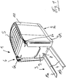
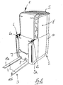
- an inventive truck 1 which comprises a drive part 2 and a load part 3, which is formed by a trained as a load lifting device 4.
- the truck 1 can optionally be operated by an operator or operated in an unmanned automated operation.
- the drive part 2 is provided with a raised and lowered driver safety roof 5.
- the driver's roof 5 in a lowered and retracted position for unmanned automated operation.
- the truck 1 By lifting and extending the driver's roof 5 upwards, the truck 1 in the in the FIG. 2 shown operating position in which within the raised driver's roof 5 a driver's workplace F is designed for an operator in the drive part 2 and the truck 1 can be operated by an operator.
- a mast 6 for raising and lowering the load-receiving means 4 is arranged.
- the mast 6 consists of two spaced apart in the vehicle transverse direction telescopic mast columns 6a, 6b.
- the load-receiving means 4 designed as a load fork consists of two fork tines 11a, 11b which are arranged on a fork carriage 7 which can be raised and lowered in the telescopic mast 6.
- the forks 11a, 11b have about a horizontal pivot axis 8 hingedly arranged load sections, which can be folded in particular by 90 ° upwards.
- FIG. 1 and 2 are the load sections of the forks 11a, 11b in a downwardly unfolded, substantially horizontal position in which with the forks 11a, 11b, a carrier can be raised.
- FIG. 7 are the folding forks 11a, 11b shown in a folded about the pivot axis 8 upwards position in which the forks 11a, 11b are folded up to the mast 6 and are preferably folded flush with the mast 6.
- the folding movement of the forks 11a, 11b can be achieved by a drive device, not shown.
- the truck 1 is designed as a battery-electrically operated truck, wherein on the second, the mast 6 opposite end portion of the drive part 2 in the FIG. 3 Traction battery 10 shown in more detail, for example, a lithium-ion battery is arranged.
- the load-facing area of the drive part 2 - as in the FIG. 3 is shown in more detail - provided with close-to-wheels 9a.
- at least one load-distant wheel 9b is arranged on the load-remote area of the drive part 2.
- the off-load wheel 9b is designed as a steerable drive wheel, wherein the wheels close to the load 9a are formed as rollers.
- the traction drive is formed by at least one electric traction motor.
- traction battery 10 In the field of traction battery 10 is also a unit space for a working hydraulic unit, not shown, for supplying a lifting drive, formed by means of which the mast 6 arranged on the load-receiving means 4 and is movable up and down to supply possibly existing hydraulic auxiliary drives or additional consumer serves.
- the arranged in the drive part 2 traction battery 10 further has the function of the load part 3 opposite counterweight of the truck 1.
- the traction battery 10 is preferably arranged in the transverse direction of the truck 1 and extends over the entire vehicle width.
- the driver's workplace F for an operator is arranged between the load part 3 and acting as a counterweight 11 traction battery 10 on the drive part 2 and comprises - as in connection with the FIG. 4 is further apparent - designed as a platform platform platform 15 and a driver's seat 16.
- a Ein- and Exit into the driver's workstation 5 can be formed by a door 17 arranged on a vehicle side.
- the driver's workplace F is at the remote end of the drive part 2 by a vertical, arranged in the vehicle transverse direction boundary wall 18 and the door 17 opposite side of the vehicle by a vertical, extending in the vehicle longitudinal boundary wall 19 limited.
- the two boundary walls 18 and 19 are arranged adjacent to each other and merge into each other in a transition region.
- the two boundary walls 18, 19 thus form a side boundary 20 of the driver's workplace F on two adjacent sides aneinder.
- the driver's seat 16 may be slidably disposed along the side boundary 20 formed by the two boundary walls 18, 19 and in the circumferential direction of the side boundary 20 of the driver's workplace F.
- a linear guide means 25 For longitudinal displacement of the driver's seat 16 along the two boundary walls 18, 19, a linear guide means 25 is provided.
- the linear guide means 25 has an arranged on the side boundary 20 and thus the two boundary walls 18, 19 of the driver's workplace F guide rail or cam track 26 on which the driver's seat 16 is arranged by means of a console 27 to achieve various operating positions for the operator slidably.
- the console 27 is preferably located on one side of the driver's seat sixteenth
- the driver's seat 16 is provided with a side armrest 30 on which one or more operating elements 31 are arranged.
- an example designed as a joystick control element 31 is arranged on the armrest 30, with which the drive and / or the steering of the truck 1 can be controlled.
- the driver's seat 16 is preferably designed as a so-called combination seat 40, which has the function of a seat for a seated operating position and the function of a standing aid for a standing operating position of the operator.
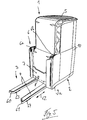
- the truck 1 is inventively provided on the drive part 2 with load arms 60, 61 which are connected to the drive part 2 between a in the FIG. 3 as well as the Figures 5 and 6 shown operating position and one in the FIGS. 1 . 2 . 4 and 7 illustrated inoperative position are arranged adjustable.
- the load arms 60, 61 slidably disposed in the bottom region of the drive part 2 in the vehicle longitudinal direction, as in the Figures 3 . 5 and 6 is illustrated by the arrow 62.
- the longitudinal guidance of the load arms 60, 61 can be effected by a linear guide, not shown.
- the displacement movement of the load arms 60, 61 between the inoperative position and the strigstallung can be achieved by means of a drive device not shown.
- the load arms 60, 61 are provided at the lastteil remedyen ends with at least one load roller roller device 63, 64 for support on the driving ban.
- the load roller devices 63, 64 consist of a single roller or alternatively may have a plurality of load rollers, for example, be designed as a tandem roller comprising two load rollers.
- the load rollers 63, 64 on the load arms 60, 61 in contact with the roadway the close-to-wheels 9a are lifted off the drive part 2 of the road.
- the load arms 60, 61 In the extended position of the load arms 60, 61, the load arms 60, 61 are located in the vertical direction under the load-receiving means 4 of the load part 3 formed by the load fork.
- the load arms 60, 61 In the retracted inoperative position are the load arms 60, 61 within the contour of the drive part 2, preferably completely below the drive part 2, and are not in the direction of the load part 3 via.
- the load rollers 63, 64 In the retracted inoperative position of the load arms 60, 61, the load rollers 63, 64 are lifted from the road, so that the truck 1 is supported in the load part side area with the wheels close to the load 9a of the drive part 2 on the road.
- the truck 1 In the inoperative position of the load arms 60, 61, the truck 1 thus has one of the wheels close to the load 9a and the load-distant wheel 9b of the drive part 2 formed chassis, whose wheelbase is determined by the distance of the wheels 9a, 9b in the vehicle longitudinal direction.
- the close-wheels 9a of the drive part 2 are lifted from the road, so that the truck 1 in the load section 3 with the load rollers 63, 64 of the extended load arms 60, 61st supported on the roadway.
- the truck 1 thus has in the operating position of the load arms 60, 61 a of the load rollers 63, 64 of the load arms 60, 61 and the load distant wheel 9b of the drive part 9b formed chassis whose wheelbase by the distance of the load rollers 63, 64 on the load arms 6, 61 and the wheel 9b is determined in the vehicle longitudinal direction.
- the load arms 60, 61 thus have the function of load supports with which the wheelbase of the truck 1 can be extended.
- load arms 60, 61 When in the inoperative position load arms 60, 61, the truck operates in the manner of a counterbalance forklift, in which the load on the load-bearing means 4 is supported outside the wheel base cantilevered.
- load arms 60, 61 in the operative position the load is carried on the load handler 4 within the extended wheel base so that the truck 1 operates in the manner of a wheeled truck.
- the load arms 60, 61 with a by the arrow 65 in the FIG. 6 clarified clarified Initialhub founded that allows a lifting and lowering movement of the load arms 60, 61.
- the load arms 60, 61 thus form an additional load-receiving means in the operating position with which a load carrier, for example a pallet, can be lowered and lifted.
- the load arms 60, 61 thus form a second load receiving means, so that - as shown in Figure 9 - with the load arms 60, 61, a first carrier and with the raised, formed by the load lifting device 4, a second carrier can be handled and the Truck 1 allows a double-deck operation.
- the truck 1 When located in the inoperative load arms 60, 61, the truck 1 due to the acting of the counterweight traction battery 10 a reduced capacity compared to the maximum carrying capacity. With the truck 1 small, light and medium heavy loads can thus be handled by the load-receiving means 4 at low vehicle mass.
- the carrying capacity of the truck 1 by adjusting the load arms 60, 61 are increased to the operating position, so that of the truck 1 with low vehicle mass and without additional counterweight large, heavy loads in the maximum carrying capacity can be handled with low energy consumption.
- the truck 1 according to the invention can thus be adapted in a simple manner in operation to the handling of different heavy loads, in particular by extending the load arms 60, 61 in applications and workflows in which increased load capacity required, the increased capacity to handle heavy Loads is made possible.
- the truck 1 according to the invention has a reduced vehicle mass compared to classic counterbalanced forklifts with a counterweight designed as a cast component and, due to the extendable load arms 60, 61, a comparable maximum load capacity with reduced dimensions in the vehicle longitudinal direction.
- the use of the truck 1 according to the invention is facilitated as a storage truck stackable shelves and narrow storage lanes and driveways at reduced working aisles.
- the truck according to the invention Due to the reduced vehicle mass, the truck according to the invention has a low energy consumption.
- the dimensions of the truck according to the invention are further reduced by the upwardly folding load sections of the forks 11a, 11b, which compact dimensions are achieved with folded forks 11a, 11b for empty runs or in a tractor operation with attached trailers and narrow storage lanes can be traveled.
Landscapes
- Engineering & Computer Science (AREA)
- Transportation (AREA)
- Structural Engineering (AREA)
- Civil Engineering (AREA)
- Life Sciences & Earth Sciences (AREA)
- Geology (AREA)
- Mechanical Engineering (AREA)
- Forklifts And Lifting Vehicles (AREA)
Applications Claiming Priority (1)
| Application Number | Priority Date | Filing Date | Title |
|---|---|---|---|
| DE201110018800 DE102011018800A1 (de) | 2011-04-27 | 2011-04-27 | Flurförderzeug |
Publications (2)
| Publication Number | Publication Date |
|---|---|
| EP2518005A1 true EP2518005A1 (fr) | 2012-10-31 |
| EP2518005B1 EP2518005B1 (fr) | 2013-09-18 |
Family
ID=45833207
Family Applications (1)
| Application Number | Title | Priority Date | Filing Date |
|---|---|---|---|
| EP20120158762 Not-in-force EP2518005B1 (fr) | 2011-04-27 | 2012-03-09 | Chariot de manutention |
Country Status (2)
| Country | Link |
|---|---|
| EP (1) | EP2518005B1 (fr) |
| DE (1) | DE102011018800A1 (fr) |
Families Citing this family (2)
| Publication number | Priority date | Publication date | Assignee | Title |
|---|---|---|---|---|
| DE102014112405A1 (de) | 2014-05-19 | 2015-11-19 | Still Gmbh | Verfahren zur Steuerung eines Flurförderzeugs |
| DE102014107065A1 (de) | 2014-05-19 | 2015-11-19 | Still Gmbh | Verfahren zur Lenkungssteuerung bei einem Flurförderzeug |
Citations (7)
| Publication number | Priority date | Publication date | Assignee | Title |
|---|---|---|---|---|
| US5174415A (en) * | 1991-12-16 | 1992-12-29 | Teledyne Princeton, Inc. | Walk behind fork lift truck |
| NL1001917C2 (nl) * | 1995-12-15 | 1997-06-17 | Kooi Bv | Meeneemvorkhefwagen. |
| US5722511A (en) * | 1994-10-17 | 1998-03-03 | Bishamon Industries Corporation | Lifting vehicle and method of operating the vehicle |
| US6343674B1 (en) * | 1999-03-03 | 2002-02-05 | Hugh Sexsmith | Multi-terrain vertical lift transporter |
| US20080164101A1 (en) * | 2007-01-08 | 2008-07-10 | Bishamon Industries Corporation | Lift for skids and pallets |
| DE102007049392A1 (de) | 2007-05-29 | 2008-12-04 | Linde Material Handling Gmbh | Gabelstapler |
| CN201240810Y (zh) * | 2008-07-01 | 2009-05-20 | 林超 | 新型手动提升机 |
-
2011
- 2011-04-27 DE DE201110018800 patent/DE102011018800A1/de not_active Withdrawn
-
2012
- 2012-03-09 EP EP20120158762 patent/EP2518005B1/fr not_active Not-in-force
Patent Citations (7)
| Publication number | Priority date | Publication date | Assignee | Title |
|---|---|---|---|---|
| US5174415A (en) * | 1991-12-16 | 1992-12-29 | Teledyne Princeton, Inc. | Walk behind fork lift truck |
| US5722511A (en) * | 1994-10-17 | 1998-03-03 | Bishamon Industries Corporation | Lifting vehicle and method of operating the vehicle |
| NL1001917C2 (nl) * | 1995-12-15 | 1997-06-17 | Kooi Bv | Meeneemvorkhefwagen. |
| US6343674B1 (en) * | 1999-03-03 | 2002-02-05 | Hugh Sexsmith | Multi-terrain vertical lift transporter |
| US20080164101A1 (en) * | 2007-01-08 | 2008-07-10 | Bishamon Industries Corporation | Lift for skids and pallets |
| DE102007049392A1 (de) | 2007-05-29 | 2008-12-04 | Linde Material Handling Gmbh | Gabelstapler |
| CN201240810Y (zh) * | 2008-07-01 | 2009-05-20 | 林超 | 新型手动提升机 |
Also Published As
| Publication number | Publication date |
|---|---|
| EP2518005B1 (fr) | 2013-09-18 |
| DE102011018800A1 (de) | 2012-10-31 |
Similar Documents
| Publication | Publication Date | Title |
|---|---|---|
| EP2641862B1 (fr) | Gerbeur à conducteur à pied | |
| EP2805911B1 (fr) | Chariot de manutention, notamment chariot de préparation, avec poste de conduite relevable et abaissable | |
| EP0916615B1 (fr) | Véhicule sans conducteur, p. ex. véhicule de transport à navigation libre pour manipuler des charges | |
| DE3017456A1 (de) | Hochregalstapler | |
| EP1698584A1 (fr) | Chariot de manutention | |
| DE102018112566A1 (de) | Flurförderzeug mit ausfahrbarer Struktur | |
| EP3272699B1 (fr) | Empileur d'étagères | |
| EP2518007B1 (fr) | Chariot de manutention, en particulier chariot élévateur à fourche équipé d'un contrepoids | |
| DE2017624A1 (de) | Lasttragwagen für schmale Gänge | |
| EP2518005B1 (fr) | Chariot de manutention | |
| DE102006000654B4 (de) | Verfahren und Anordnung zum Wenden von Paletten | |
| EP0151624B1 (fr) | Vehicule de transport | |
| DE29620342U1 (de) | Satellitenfahrzeug | |
| EP4067288B1 (fr) | Dispositif de levage et de déplacement | |
| WO2006122336A1 (fr) | Remorque pour un vehicule automobile | |
| DE102016104745A1 (de) | Mitgängergeführter Hubwagen | |
| DE10001666A1 (de) | Flurförderzeug | |
| EP4206116B1 (fr) | Chariot de manutention, en particulier chariot élévateur à voie étroite | |
| DE102015100815A1 (de) | Mitnahmestapler | |
| EP2518006B1 (fr) | Chariot de manutention doté d'un protège-conducteur | |
| DE102018109554A1 (de) | Flurförderzeugflotte | |
| DE1166699B (de) | Seitenlader mit mittigem Hubmast | |
| DE1431701A1 (de) | Fahrbarer Gabel- und Hubstapler | |
| DE102006025164A1 (de) | Hochregalflurförderzeug mit verstellbaren Lasträdern | |
| DE202007008131U1 (de) | Seitenschubgerät |
Legal Events
| Date | Code | Title | Description |
|---|---|---|---|
| PUAI | Public reference made under article 153(3) epc to a published international application that has entered the european phase |
Free format text: ORIGINAL CODE: 0009012 |
|
| AK | Designated contracting states |
Kind code of ref document: A1 Designated state(s): AL AT BE BG CH CY CZ DE DK EE ES FI FR GB GR HR HU IE IS IT LI LT LU LV MC MK MT NL NO PL PT RO RS SE SI SK SM TR |
|
| AX | Request for extension of the european patent |
Extension state: BA ME |
|
| 17P | Request for examination filed |
Effective date: 20130320 |
|
| GRAP | Despatch of communication of intention to grant a patent |
Free format text: ORIGINAL CODE: EPIDOSNIGR1 |
|
| RIC1 | Information provided on ipc code assigned before grant |
Ipc: B66F 9/075 20060101AFI20130516BHEP Ipc: B66F 9/16 20060101ALI20130516BHEP |
|
| INTG | Intention to grant announced |
Effective date: 20130604 |
|
| GRAS | Grant fee paid |
Free format text: ORIGINAL CODE: EPIDOSNIGR3 |
|
| GRAA | (expected) grant |
Free format text: ORIGINAL CODE: 0009210 |
|
| AK | Designated contracting states |
Kind code of ref document: B1 Designated state(s): AL AT BE BG CH CY CZ DE DK EE ES FI FR GB GR HR HU IE IS IT LI LT LU LV MC MK MT NL NO PL PT RO RS SE SI SK SM TR |
|
| REG | Reference to a national code |
Ref country code: GB Ref legal event code: FG4D Free format text: NOT ENGLISH |
|
| REG | Reference to a national code |
Ref country code: CH Ref legal event code: EP |
|
| REG | Reference to a national code |
Ref country code: IE Ref legal event code: FG4D Free format text: LANGUAGE OF EP DOCUMENT: GERMAN |
|
| REG | Reference to a national code |
Ref country code: AT Ref legal event code: REF Ref document number: 632649 Country of ref document: AT Kind code of ref document: T Effective date: 20131015 |
|
| REG | Reference to a national code |
Ref country code: DE Ref legal event code: R096 Ref document number: 502012000125 Country of ref document: DE Effective date: 20131114 |
|
| REG | Reference to a national code |
Ref country code: SE Ref legal event code: TRGR |
|
| PG25 | Lapsed in a contracting state [announced via postgrant information from national office to epo] |
Ref country code: CY Free format text: LAPSE BECAUSE OF FAILURE TO SUBMIT A TRANSLATION OF THE DESCRIPTION OR TO PAY THE FEE WITHIN THE PRESCRIBED TIME-LIMIT Effective date: 20130918 Ref country code: HR Free format text: LAPSE BECAUSE OF FAILURE TO SUBMIT A TRANSLATION OF THE DESCRIPTION OR TO PAY THE FEE WITHIN THE PRESCRIBED TIME-LIMIT Effective date: 20130918 Ref country code: NO Free format text: LAPSE BECAUSE OF FAILURE TO SUBMIT A TRANSLATION OF THE DESCRIPTION OR TO PAY THE FEE WITHIN THE PRESCRIBED TIME-LIMIT Effective date: 20131218 Ref country code: LT Free format text: LAPSE BECAUSE OF FAILURE TO SUBMIT A TRANSLATION OF THE DESCRIPTION OR TO PAY THE FEE WITHIN THE PRESCRIBED TIME-LIMIT Effective date: 20130918 |
|
| REG | Reference to a national code |
Ref country code: NL Ref legal event code: VDEP Effective date: 20130918 |
|
| REG | Reference to a national code |
Ref country code: LT Ref legal event code: MG4D |
|
| PG25 | Lapsed in a contracting state [announced via postgrant information from national office to epo] |
Ref country code: RS Free format text: LAPSE BECAUSE OF FAILURE TO SUBMIT A TRANSLATION OF THE DESCRIPTION OR TO PAY THE FEE WITHIN THE PRESCRIBED TIME-LIMIT Effective date: 20130918 Ref country code: FI Free format text: LAPSE BECAUSE OF FAILURE TO SUBMIT A TRANSLATION OF THE DESCRIPTION OR TO PAY THE FEE WITHIN THE PRESCRIBED TIME-LIMIT Effective date: 20130918 Ref country code: SI Free format text: LAPSE BECAUSE OF FAILURE TO SUBMIT A TRANSLATION OF THE DESCRIPTION OR TO PAY THE FEE WITHIN THE PRESCRIBED TIME-LIMIT Effective date: 20130918 Ref country code: LV Free format text: LAPSE BECAUSE OF FAILURE TO SUBMIT A TRANSLATION OF THE DESCRIPTION OR TO PAY THE FEE WITHIN THE PRESCRIBED TIME-LIMIT Effective date: 20130918 Ref country code: GR Free format text: LAPSE BECAUSE OF FAILURE TO SUBMIT A TRANSLATION OF THE DESCRIPTION OR TO PAY THE FEE WITHIN THE PRESCRIBED TIME-LIMIT Effective date: 20131219 |
|
| PG25 | Lapsed in a contracting state [announced via postgrant information from national office to epo] |
Ref country code: NL Free format text: LAPSE BECAUSE OF FAILURE TO SUBMIT A TRANSLATION OF THE DESCRIPTION OR TO PAY THE FEE WITHIN THE PRESCRIBED TIME-LIMIT Effective date: 20130918 Ref country code: EE Free format text: LAPSE BECAUSE OF FAILURE TO SUBMIT A TRANSLATION OF THE DESCRIPTION OR TO PAY THE FEE WITHIN THE PRESCRIBED TIME-LIMIT Effective date: 20130918 Ref country code: SK Free format text: LAPSE BECAUSE OF FAILURE TO SUBMIT A TRANSLATION OF THE DESCRIPTION OR TO PAY THE FEE WITHIN THE PRESCRIBED TIME-LIMIT Effective date: 20130918 Ref country code: IS Free format text: LAPSE BECAUSE OF FAILURE TO SUBMIT A TRANSLATION OF THE DESCRIPTION OR TO PAY THE FEE WITHIN THE PRESCRIBED TIME-LIMIT Effective date: 20140118 Ref country code: CZ Free format text: LAPSE BECAUSE OF FAILURE TO SUBMIT A TRANSLATION OF THE DESCRIPTION OR TO PAY THE FEE WITHIN THE PRESCRIBED TIME-LIMIT Effective date: 20130918 |
|
| PG25 | Lapsed in a contracting state [announced via postgrant information from national office to epo] |
Ref country code: ES Free format text: LAPSE BECAUSE OF FAILURE TO SUBMIT A TRANSLATION OF THE DESCRIPTION OR TO PAY THE FEE WITHIN THE PRESCRIBED TIME-LIMIT Effective date: 20130918 Ref country code: PL Free format text: LAPSE BECAUSE OF FAILURE TO SUBMIT A TRANSLATION OF THE DESCRIPTION OR TO PAY THE FEE WITHIN THE PRESCRIBED TIME-LIMIT Effective date: 20130918 |
|
| REG | Reference to a national code |
Ref country code: DE Ref legal event code: R097 Ref document number: 502012000125 Country of ref document: DE |
|
| PG25 | Lapsed in a contracting state [announced via postgrant information from national office to epo] |
Ref country code: PT Free format text: LAPSE BECAUSE OF FAILURE TO SUBMIT A TRANSLATION OF THE DESCRIPTION OR TO PAY THE FEE WITHIN THE PRESCRIBED TIME-LIMIT Effective date: 20140120 |
|
| PLBE | No opposition filed within time limit |
Free format text: ORIGINAL CODE: 0009261 |
|
| STAA | Information on the status of an ep patent application or granted ep patent |
Free format text: STATUS: NO OPPOSITION FILED WITHIN TIME LIMIT |
|
| 26N | No opposition filed |
Effective date: 20140619 |
|
| PG25 | Lapsed in a contracting state [announced via postgrant information from national office to epo] |
Ref country code: DK Free format text: LAPSE BECAUSE OF FAILURE TO SUBMIT A TRANSLATION OF THE DESCRIPTION OR TO PAY THE FEE WITHIN THE PRESCRIBED TIME-LIMIT Effective date: 20130918 |
|
| REG | Reference to a national code |
Ref country code: DE Ref legal event code: R097 Ref document number: 502012000125 Country of ref document: DE Effective date: 20140619 |
|
| PG25 | Lapsed in a contracting state [announced via postgrant information from national office to epo] |
Ref country code: LU Free format text: LAPSE BECAUSE OF FAILURE TO SUBMIT A TRANSLATION OF THE DESCRIPTION OR TO PAY THE FEE WITHIN THE PRESCRIBED TIME-LIMIT Effective date: 20140309 |
|
| REG | Reference to a national code |
Ref country code: IE Ref legal event code: MM4A |
|
| PG25 | Lapsed in a contracting state [announced via postgrant information from national office to epo] |
Ref country code: IE Free format text: LAPSE BECAUSE OF NON-PAYMENT OF DUE FEES Effective date: 20140309 |
|
| REG | Reference to a national code |
Ref country code: CH Ref legal event code: PL |
|
| PG25 | Lapsed in a contracting state [announced via postgrant information from national office to epo] |
Ref country code: CH Free format text: LAPSE BECAUSE OF NON-PAYMENT OF DUE FEES Effective date: 20150331 Ref country code: LI Free format text: LAPSE BECAUSE OF NON-PAYMENT OF DUE FEES Effective date: 20150331 |
|
| PG25 | Lapsed in a contracting state [announced via postgrant information from national office to epo] |
Ref country code: MT Free format text: LAPSE BECAUSE OF FAILURE TO SUBMIT A TRANSLATION OF THE DESCRIPTION OR TO PAY THE FEE WITHIN THE PRESCRIBED TIME-LIMIT Effective date: 20130918 |
|
| REG | Reference to a national code |
Ref country code: FR Ref legal event code: PLFP Year of fee payment: 5 |
|
| PG25 | Lapsed in a contracting state [announced via postgrant information from national office to epo] |
Ref country code: SM Free format text: LAPSE BECAUSE OF FAILURE TO SUBMIT A TRANSLATION OF THE DESCRIPTION OR TO PAY THE FEE WITHIN THE PRESCRIBED TIME-LIMIT Effective date: 20130918 |
|
| PG25 | Lapsed in a contracting state [announced via postgrant information from national office to epo] |
Ref country code: MC Free format text: LAPSE BECAUSE OF FAILURE TO SUBMIT A TRANSLATION OF THE DESCRIPTION OR TO PAY THE FEE WITHIN THE PRESCRIBED TIME-LIMIT Effective date: 20130918 Ref country code: RO Free format text: LAPSE BECAUSE OF FAILURE TO SUBMIT A TRANSLATION OF THE DESCRIPTION OR TO PAY THE FEE WITHIN THE PRESCRIBED TIME-LIMIT Effective date: 20130918 |
|
| PG25 | Lapsed in a contracting state [announced via postgrant information from national office to epo] |
Ref country code: BG Free format text: LAPSE BECAUSE OF FAILURE TO SUBMIT A TRANSLATION OF THE DESCRIPTION OR TO PAY THE FEE WITHIN THE PRESCRIBED TIME-LIMIT Effective date: 20130918 |
|
| PG25 | Lapsed in a contracting state [announced via postgrant information from national office to epo] |
Ref country code: HU Free format text: LAPSE BECAUSE OF FAILURE TO SUBMIT A TRANSLATION OF THE DESCRIPTION OR TO PAY THE FEE WITHIN THE PRESCRIBED TIME-LIMIT; INVALID AB INITIO Effective date: 20120309 Ref country code: BE Free format text: LAPSE BECAUSE OF FAILURE TO SUBMIT A TRANSLATION OF THE DESCRIPTION OR TO PAY THE FEE WITHIN THE PRESCRIBED TIME-LIMIT Effective date: 20140331 Ref country code: TR Free format text: LAPSE BECAUSE OF FAILURE TO SUBMIT A TRANSLATION OF THE DESCRIPTION OR TO PAY THE FEE WITHIN THE PRESCRIBED TIME-LIMIT Effective date: 20130918 |
|
| GBPC | Gb: european patent ceased through non-payment of renewal fee |
Effective date: 20160309 |
|
| REG | Reference to a national code |
Ref country code: DE Ref legal event code: R082 Ref document number: 502012000125 Country of ref document: DE Representative=s name: PATENTSHIP PATENTANWALTSGESELLSCHAFT MBH, DE |
|
| PG25 | Lapsed in a contracting state [announced via postgrant information from national office to epo] |
Ref country code: GB Free format text: LAPSE BECAUSE OF NON-PAYMENT OF DUE FEES Effective date: 20160309 |
|
| REG | Reference to a national code |
Ref country code: DE Ref legal event code: R082 Ref document number: 502012000125 Country of ref document: DE Representative=s name: PATENTSHIP PATENTANWALTSGESELLSCHAFT MBH, DE |
|
| REG | Reference to a national code |
Ref country code: FR Ref legal event code: PLFP Year of fee payment: 6 |
|
| PGFP | Annual fee paid to national office [announced via postgrant information from national office to epo] |
Ref country code: SE Payment date: 20170327 Year of fee payment: 6 Ref country code: DE Payment date: 20170327 Year of fee payment: 6 Ref country code: FR Payment date: 20170323 Year of fee payment: 6 |
|
| PGFP | Annual fee paid to national office [announced via postgrant information from national office to epo] |
Ref country code: IT Payment date: 20170323 Year of fee payment: 6 |
|
| REG | Reference to a national code |
Ref country code: AT Ref legal event code: MM01 Ref document number: 632649 Country of ref document: AT Kind code of ref document: T Effective date: 20170309 |
|
| PG25 | Lapsed in a contracting state [announced via postgrant information from national office to epo] |
Ref country code: MK Free format text: LAPSE BECAUSE OF FAILURE TO SUBMIT A TRANSLATION OF THE DESCRIPTION OR TO PAY THE FEE WITHIN THE PRESCRIBED TIME-LIMIT Effective date: 20130918 |
|
| PG25 | Lapsed in a contracting state [announced via postgrant information from national office to epo] |
Ref country code: AT Free format text: LAPSE BECAUSE OF NON-PAYMENT OF DUE FEES Effective date: 20170309 |
|
| REG | Reference to a national code |
Ref country code: DE Ref legal event code: R119 Ref document number: 502012000125 Country of ref document: DE |
|
| PG25 | Lapsed in a contracting state [announced via postgrant information from national office to epo] |
Ref country code: AL Free format text: LAPSE BECAUSE OF FAILURE TO SUBMIT A TRANSLATION OF THE DESCRIPTION OR TO PAY THE FEE WITHIN THE PRESCRIBED TIME-LIMIT Effective date: 20130918 Ref country code: SE Free format text: LAPSE BECAUSE OF NON-PAYMENT OF DUE FEES Effective date: 20180310 |
|
| PG25 | Lapsed in a contracting state [announced via postgrant information from national office to epo] |
Ref country code: DE Free format text: LAPSE BECAUSE OF NON-PAYMENT OF DUE FEES Effective date: 20181002 |
|
| PG25 | Lapsed in a contracting state [announced via postgrant information from national office to epo] |
Ref country code: IT Free format text: LAPSE BECAUSE OF NON-PAYMENT OF DUE FEES Effective date: 20180309 |
|
| PG25 | Lapsed in a contracting state [announced via postgrant information from national office to epo] |
Ref country code: FR Free format text: LAPSE BECAUSE OF NON-PAYMENT OF DUE FEES Effective date: 20180331 |