EP2518228A2 - Vorrichtung zum Verdecken einer Platte in Zusammenhang mit Überlaufinstallation - Google Patents
Vorrichtung zum Verdecken einer Platte in Zusammenhang mit Überlaufinstallation Download PDFInfo
- Publication number
- EP2518228A2 EP2518228A2 EP12002970A EP12002970A EP2518228A2 EP 2518228 A2 EP2518228 A2 EP 2518228A2 EP 12002970 A EP12002970 A EP 12002970A EP 12002970 A EP12002970 A EP 12002970A EP 2518228 A2 EP2518228 A2 EP 2518228A2
- Authority
- EP
- European Patent Office
- Prior art keywords
- overflow
- adapter
- plate
- sidewall
- overflow plate
- Prior art date
- Legal status (The legal status is an assumption and is not a legal conclusion. Google has not performed a legal analysis and makes no representation as to the accuracy of the status listed.)
- Withdrawn
Links
- 238000009428 plumbing Methods 0.000 title description 9
- 239000012530 fluid Substances 0.000 claims description 29
- 239000000853 adhesive Substances 0.000 claims description 9
- 230000001070 adhesive effect Effects 0.000 claims description 9
- 230000008439 repair process Effects 0.000 abstract description 2
- 230000014759 maintenance of location Effects 0.000 description 40
- 239000002351 wastewater Substances 0.000 description 11
- 238000000034 method Methods 0.000 description 10
- 230000004075 alteration Effects 0.000 description 3
- XLYOFNOQVPJJNP-UHFFFAOYSA-N water Substances O XLYOFNOQVPJJNP-UHFFFAOYSA-N 0.000 description 3
- 230000008859 change Effects 0.000 description 2
- 239000000463 material Substances 0.000 description 2
- 230000007246 mechanism Effects 0.000 description 2
- 238000012986 modification Methods 0.000 description 2
- 230000004048 modification Effects 0.000 description 2
- 238000007789 sealing Methods 0.000 description 2
- VYZAMTAEIAYCRO-UHFFFAOYSA-N Chromium Chemical compound [Cr] VYZAMTAEIAYCRO-UHFFFAOYSA-N 0.000 description 1
- 230000000712 assembly Effects 0.000 description 1
- 238000000429 assembly Methods 0.000 description 1
- 230000008901 benefit Effects 0.000 description 1
- 238000010348 incorporation Methods 0.000 description 1
- 239000007788 liquid Substances 0.000 description 1
- 238000004519 manufacturing process Methods 0.000 description 1
- 239000000565 sealant Substances 0.000 description 1
- 230000000153 supplemental effect Effects 0.000 description 1
- 238000012360 testing method Methods 0.000 description 1
- 239000002699 waste material Substances 0.000 description 1
Images






Classifications
-
- E—FIXED CONSTRUCTIONS
- E03—WATER SUPPLY; SEWERAGE
- E03C—DOMESTIC PLUMBING INSTALLATIONS FOR FRESH WATER OR WASTE WATER; SINKS
- E03C1/00—Domestic plumbing installations for fresh water or waste water; Sinks
- E03C1/12—Plumbing installations for waste water; Basins or fountains connected thereto; Sinks
- E03C1/24—Overflow devices for basins or baths
-
- E—FIXED CONSTRUCTIONS
- E03—WATER SUPPLY; SEWERAGE
- E03C—DOMESTIC PLUMBING INSTALLATIONS FOR FRESH WATER OR WASTE WATER; SINKS
- E03C1/00—Domestic plumbing installations for fresh water or waste water; Sinks
- E03C1/12—Plumbing installations for waste water; Basins or fountains connected thereto; Sinks
- E03C1/24—Overflow devices for basins or baths
- E03C1/244—Separate devices to be placed on the outlet opening
-
- E—FIXED CONSTRUCTIONS
- E03—WATER SUPPLY; SEWERAGE
- E03C—DOMESTIC PLUMBING INSTALLATIONS FOR FRESH WATER OR WASTE WATER; SINKS
- E03C1/00—Domestic plumbing installations for fresh water or waste water; Sinks
- E03C1/12—Plumbing installations for waste water; Basins or fountains connected thereto; Sinks
- E03C1/24—Overflow devices for basins or baths
- E03C2001/2406—Overflow alarm devices
Definitions
- Embodiments of the present invention generally relate to devices for concealing a portion of a bathtub's overflow plumbing.
- One embodiment of the present invention employs a cover that conceals an existing overflow plate, which allows selective alterations or repairs to the overflow plumbing.
- Overflow plumbing is commonly associated with basins for holding fluids. Overflow systems provide an access point for drain clean out and may help address substantial overfilling of the basin.
- Bathtubs for example, employ overflow assemblies comprised of an overflow pipe that is associated with an outlet port of the bathtub and that is interconnected to a sidewall of the bathtub.
- An overflow plate conceals the outlet port.
- the overflow plate includes at least one fluid flow opening that allows water to flow from the bathtub to the overflow pipe if the need arises.
- Ball I provides an overflow plumbing system having an overflow pipe that is associated with a bathtub having a cover plate interconnected to the overflow pipe by way of at least one fastener.
- the fasteners cooperate with bosses associated with the overflow pipe to hold the cover in place.
- the overflow system of Ball I is primarily aligned with the outer portion surface of the bathtub and requires an interconnected sleeve to engage an inner surface of the bathtub to secure the overflow pipe to the bathtub.
- One of skill in the art will appreciate that the aligning of the sleeve and the overflow pipe is difficult as the overflow pipe is located behind the bathtub wall and is, thus, out of view and difficult to access.
- interconnection of the screw to the bosses of the overflow pipe is difficult. These factors make replacing overflow plates commonly found in many bathrooms difficult, time consuming, and expensive.
- Ball II discloses a cover having a clip integrated on an interior surface thereof. To install, the clip is at least partially slid into a fluid opening associated with the existing overflow plate. The clip holds the replacement cover in place and conceals the existing plate while maintaining an opening that allows fluid to flow from the bathtub to the overflow pipe.
- One drawback with Ball II is that the clip may fail or the replacement cover may loosen over time, thereby allowing the cover to slip relative to the overflow plate which could mar the inner surface of the bathtub.
- the clip obstructs the fluid opening provided by the existing overflow plate, which may decrease fluid flow rate into the overflow pipe.
- the device of Ball II may not fit accommodate many overflow plates.
- overflow systems of some bathtubs are comprised of an overflow pipe having a plate for association with an outer surface of a bathtub.
- a sleeve is interconnected to the overflow pipe wherein an inner surface of the sleeve and the plate firmly engage the bathtub to secure the overflow pipe. That is, the bathtub wall is positioned between the inner surface of the sleeve and the plate, thereby securing the overflow pipe to the bathtub.
- an overflow plate is included that is interconnected to the sleeve and/or overflow pipe by way of at least one screw or other fastening mechanism.
- Embodiments of the present invention can be used in conjunction with many overflow systems.
- the overflow plate includes at least one opening that allows a fluid from inside the bathtub to enter into the sleeve and overflow pipe when the liquid level in the bathtub reaches a predetermined level.
- One embodiment of the present invention is an overflow plate cover having an outer surface with a wall extending therefrom.
- the wall includes an aperture that aligns with the fluid opening of the overflow plate to maintain a fluid passage from inside the bathtub to the overflow pipe.
- the contemplated cover is associated with the overflow plate by way of a retention plate, which will be described in further detail below.
- fasteners which interconnect the overflow plate to the overflow pipe, are loosened to allow the overflow plate to be separated from the bathtub wall.
- the retention plate is positioned between the overflow plate and the bathtub wall. The fasteners are tightened to affix the retention plate between the overflow plate and the bathtub wall.
- One embodiment of the present invention includes a retention plate with a lip that selectively receives at least one protrusion associated with the wall of the overflow plate cover to secure the overflow plate cover.
- the overflow plate cover is able to rotate, i.e., about a normal axis thereof, relative to the retention plate. To ensure the fluid passage is unobstructed, an aperture or cut out in the overflow plate cover wall is rotated and positioned generally in line with the fluid opening of the overflow plate.
- the overflow plate cover is glued or otherwise bonded to the bathtub wall.
- the overflow plate cover of this embodiment of the present invention would also include an outer surface and an inner surface with a wall depending therefrom. The inner surface is spaced from an outer surface of the overflow plate.
- the wall also includes an outwardly or inwardly extending lip to receive the bonding material and is associated with the bathtub wall.
- overflow plate cover that will conceal overflow plates of various styles, sizes, and shapes.
- overflow plates are not standard.
- One embodiment of the present invention is thus of such size and shape to accommodate most, if not all, of the overflow plates on the market.
- the present invention provide an overflow plate cover that accommodates overflow plates of various designs. More specifically, when installed, overflow plates used in some parts of the world, such as Europe, are spaced from the inner surface and extend into the bathtub. These overflow plates include a sidewall with an interconnected flange that abuts the inner surface of the bathtub, a plurality of holes that allows water to enter the overflow pipe, and an anchor for securing a drain stopper chain. As these types of overflow plates are very difficult to remove, one embodiment of the present invention provides an adapter that interfaces with the overflow port flange. The adapter also includes an outer edge that selectively receives the internal surface of the overflow plate cover similar to the embodiment described above.
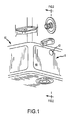
- an overflow system of the prior art employs an overflow pipe 2 is associated with a sidewall 6 of a bathtub 10.
- the overflow pipe 2 includes a plate 14 that is abutted against an outer surface of the bathtub 10.
- a sleeve 22 having an inner surface 26 is abutted against an inner surface 30 of the bathtub wall 6 to secure the overflow pipe 2 to the bathtub 10.
- the sleeve 22 is associated with the overflow pipe 2 by a threaded interconnection, a friction fit, or any other common attachment scheme.
- an overflow plate 42 is employed that utilizes the screw 34 to interconnect to the sleeve 22 and/or overflow pipe 2.
- the overflow plate 42 includes an outer surface 46 that conceals the outlet port 38 of the bathtub 10 and a fluid opening 50 that allows fluid to flow within the bathtub 10 and into the overflow pipe 2.
- an overflow plate cover 54 is employed to conceal the overflow plate 42.
- overflow plate cover 54 of the present invention includes an outer surface 58 having a wall 62 depending therefrom. Although shown as cylindrical, one 9 skilled in the art will appreciate that the overflow plate cover 54 may be of any shape and be made of any material or finish.
- the wall 62 includes at least one opening 66 therethrough that is aligned with a fluid opening 50 of the overflow plate 42.
- the opening 66 may also be an enlarged cut out similar to that of the existing overflow plate opening 50 shown, thereby increasing the fluid flow capacity of the overflow plate cover.
- the screw 34 or screws associated with the overflow plate 42 are loosened, but not completely removed, to allow the overflow plate 42 to be separated from the bathtub wall 6 and a retention plate 70 to be inserted between the overflow plate 4 and the bathtub well 6.
- the screw 34 may be removed completely, but those skilled in the art will appreciate that doing so would make it difficult to reconnect the overflow plate 42.
- the overflow plate cover 54 is associated with the retention plate 70 to conceal the overflow plate 42.
- the overflow plate cover 54 detachably engages the outer edge of the retention plate 70.
- the retention plate 70 may include a lip 74, hooks, lugs, or other mechanisms that cooperate with protrusions (now shown) integrated into the inner portion of the wall 62. Such interconnection scheme is similar to that shown in U.S. Patent Application Publication No. 2004/0117907 , which is incorporated by reference in its entirety herein.
- the lip 74 also maintains the retention plate 70 in place so that it will not fall behind the loosen overflow plate 42.
- the overflow plate cover 54 may be interconnected to the retention plate 70 in other ways, such as bonding or with other types of interference fit.
- an overflow plate cover 154 of another embodiment of the present invention is shown that includes a wall 162 with a lip 170.
- the lip 170 receives a sealant or an adhesive and directly bonds to the bathtub wall 6.
- One drawback of this system compared to the embodiment of Fig. 4 is that the interconnection is permanent or semi-permanent and may mar the inner surface 30 of the bathtub.
- an inner surface 174 of the overflow plate cover 154 may include inner-extending protrusions that interface with the outer surface 46 of the overflow plate 42.
- the overflow plate cover includes an opening 166 that communicates with the opening 50 of the overflow plate 42, as does the overflow plate cover.
- FIGs. 6 and 7 another embodiment of the present invention is shown that employs an upper retention plate 178 and a lower retention plate 182 that work in conjunction to receive and secure the overflow plate cover 54.
- the upper retention plate 178 is selectively interconnected to the lower retention plate 182 wherein both the upper retention plate 178 and the lower retention plate 182 employ a series of lugs 186 that interface with an inner surface of the overflow plate cover 54.
- This interconnection scheme is similar to that disclosed in U.S. Patent Application Publication No. 2004/0117907 .
- each plate may include at least one tab 190.
- One of the tabs 190 may also receive a chain of a chain/stopper drain closure system by way of a hole or a slot.
- the upper retention plate 178 and the lower retention plate 182 may interconnect in various ways. Here, a key and slot configuration is provided.
- lugs 186 are shown on both the upper retention plate 178 and the lower retention plate 182 only one of those members may contain lugs 186 to secure the overflow plate cover.
- the screw is re-tightened which firmly secures the upper retention plate 178 and the lower retention plate 182 between the overflow plate 42 and the sidewall 6.
- the overflow plate cover 54 is selectively and detachably interconnected to the retention plates such that the opening 66 thereof is aligned with the opening 50 of the overflow plate.
- Figs. 8-10 illustrate another method of associating an overflow plate cover to an overflow plate 204, More specifically, the overflow plates 204 of some designs are spaced from a flange 208 by a sidewall 212. Thus, when incorporated into a bathtub, the overflow plate 204 is separated from the inner surface of the bathtub by the sidewall 212. (See Fig. 10 ).
- the overflow plate 204 includes a plurality of holes 216 that allow the ingress of fluid into an overflow pipe (not shown).
- the overflow plate 204 also includes an anchor 220 that receives a chain that is also associated with a drain stopper.
- Figs. 8-10 show an adapter 224 that accommodates the sidewall 212 of the overflow plate 204.
- the adapter 224 also includes an outer edge 228 that receives and secures the overflow plate cover.
- the adapter 224 also includes an adhesive strip 232 that is removed which allows the adapter 224 to be adhered to the flange 208. Alternatively, an adhesive putty may be used to bond the adapter to the flange.
- the overflow plate cover 200 is then interconnected to the adapter 224 similar to that shown and described above wherein at least a portion of the outer edge 228 selectively receives the sidewall 236 of the overflow plate cover 200.
- An opening 240 in the overflow plate cover 200 allows water to reach the holes 216 of the overflow plate 204.
- the opening 240 may also be made larger to accommodate a drain stopper chain, if necessary.
- the outer edge 228 may include a plurality of outwardly-extending lugs, similar to the retention plates shown in Figs. 6 & 7 .
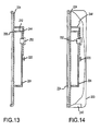
- an adapter 224 of another embodiment that includes a plate 244 that is spaced from a front surface 248 of the adapter 224.
- the plate 244 engages the overflow plate 204 as shown in Figs. 12 and 13 .
- the plate 244 is interconnected to the overflow plate 204 with a connector 252 that is fed through a hole 256 in the plate 244 and inserted into one of the holes 216 of the overflow plate 204.
- adhesives may alternatively be applied to join the plate 244 to the overflow plate.
- the angular orientation of the adapter 224 relative to the overflow plate is irrelevant. That is, the connector 252 and associated plate 244 may be associated with any of the holes 216 provided by the overflow plate 204.
- the connector 252 and the plate 244 may be integral.
- Figs. 15 and 16 show another embodiment of the adapter 224 that is associated with the overflow plate 204 with a retaining member 260.
- the retaining member 206 is threaded through a hole 264 provided by the anchor 220.
- the outer ends 268 of the retaining member 260 contact the adapter 224 to secure the adapter to the overflow plate.
- fingers 272 are employed that hold the ends 268 of the retaining member 260.
- the retaining member 260 may include a hole.
- the adapter 224 includes an extended sidewall 276.
- the distance between the overflow plate 204 and the flange 208 will dictate the width of the adapter sidewall 276.
- the extended sidewall 276 may be comprised of a plurality of selectively interconnected pieces such that the sidewall 276 depth may be selectively altered to accommodate overflow systems of various manufacture.
- the adapter 224 is abutted against the flange 208 wherein the front surface 248 of the adapter 224 is coincident or spaced somewhat from the overflow plate 204.
- the retaining member 260 is then interconnected to the anchor 220 wherein the ends 268 of the retaining member 260 contact the front surface 248 of the adapter 224.
- the ends 268 of the resilient retaining member 260 are deflected outwardly, the recoil thereof acts as a spring that helps securely associate the adapter to the overflow plate 204.
- the adapter 224 includes an outer edge 228 that is associated with a portion of the overflow plate cover 200.
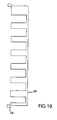
- Fig. 19 shows an adapter similar to that of Fig. 17 where portions of the sidewall have been removed.
- a spring 280 or other resilient member, is wrapped around the sidewall of the overflow assembly which maintains the relationship between the adapter 224 and the overflow plate 204.
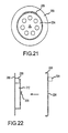
- Figs. 21-23 show yet another method of interconnecting the adapter 224 to an overflow assembly.
- the adapter 224 includes a ledge 284 that is interconnected to the sidewall 212 of the overflow port via adhesive 288.
Landscapes
- Engineering & Computer Science (AREA)
- Environmental & Geological Engineering (AREA)
- Health & Medical Sciences (AREA)
- Life Sciences & Earth Sciences (AREA)
- Hydrology & Water Resources (AREA)
- Public Health (AREA)
- Water Supply & Treatment (AREA)
- Sink And Installation For Waste Water (AREA)
- Bathtubs, Showers, And Their Attachments (AREA)
Applications Claiming Priority (1)
| Application Number | Priority Date | Filing Date | Title |
|---|---|---|---|
| US201161479063P | 2011-04-26 | 2011-04-26 |
Publications (2)
| Publication Number | Publication Date |
|---|---|
| EP2518228A2 true EP2518228A2 (de) | 2012-10-31 |
| EP2518228A3 EP2518228A3 (de) | 2014-04-23 |
Family
ID=46045709
Family Applications (1)
| Application Number | Title | Priority Date | Filing Date |
|---|---|---|---|
| EP12002970.7A Withdrawn EP2518228A3 (de) | 2011-04-26 | 2012-04-26 | Vorrichtung zum Verdecken einer Platte in Zusammenhang mit Überlaufinstallation |
Country Status (2)
| Country | Link |
|---|---|
| EP (1) | EP2518228A3 (de) |
| CA (1) | CA2775487C (de) |
Citations (20)
| Publication number | Priority date | Publication date | Assignee | Title |
|---|---|---|---|---|
| US5745931A (en) | 1996-02-09 | 1998-05-05 | Wcm Industries, Inc. | Method and means for covering the flange of a waste water strainer |
| US5758368A (en) | 1997-05-21 | 1998-06-02 | Wcm Industries, Inc. | Waste water valves for bathtubs and the like |
| US5890241A (en) | 1998-02-24 | 1999-04-06 | Wcm Industries, Inc. | Method and means for installing overflow outlets to bathtubs and the like |
| US6138298A (en) | 1999-03-01 | 2000-10-31 | Wcm Industries, Inc. | Clip on fluid overflow plate for bathtubs |
| US6148454A (en) | 1999-03-04 | 2000-11-21 | Wcm Industries, Inc. | Solenoid control for a bathtub waste water drain |
| US6154898A (en) | 1999-05-19 | 2000-12-05 | Wcm Industries, Inc. | Wastewater drain control for fluid compartments |
| US6173459B1 (en) | 1999-05-26 | 2001-01-16 | Wcm Industries, Inc. | Control for a bathtub waste water drain |
| US6226806B1 (en) | 2000-08-02 | 2001-05-08 | Wcm Industries, Inc. | Waste water strainer and valve |
| US6317906B1 (en) | 1998-03-10 | 2001-11-20 | Wcm Industries, Inc. | Strainer assembly for bathtub drains and the like |
| US6418570B1 (en) | 2001-04-04 | 2002-07-16 | Wcm Industries, Inc. | Drain closure |
| US6546573B1 (en) | 2002-07-17 | 2003-04-15 | Wcm Industries, Inc. | Drain cover assembly |
| US6675407B1 (en) | 2002-11-08 | 2004-01-13 | Wcm Industries, Inc. | Solenoid activated bathtub drain closure |
| US6681420B1 (en) | 2002-12-03 | 2004-01-27 | Wcm Industries, Inc. | Method and apparatus for installing a bathtub assembly |
| US20040117907A1 (en) | 2000-06-13 | 2004-06-24 | Wcm Industries, Inc. | Method and apparatus for assembling and sealing bathtub overflow and waste water ports |
| US20070039098A1 (en) | 2005-08-19 | 2007-02-22 | Wcm Industries, Inc. | Bath drain closure assembly |
| US20080047060A1 (en) | 2006-08-22 | 2008-02-28 | Wcm Industries, Inc. | Control for a bathtub waste water drain |
| US20080196161A1 (en) | 2004-10-22 | 2008-08-21 | Wcm Industries, Inc. | Flexible Bathtub Waste Pipe Assembly for Bathtubs and the Like |
| US7451502B2 (en) | 2005-08-23 | 2008-11-18 | Wcm Industries, Inc. | Bath drain closure assembly |
| US7503083B2 (en) | 2005-08-23 | 2009-03-17 | Wcm Industries, Inc. | Means for covering the flange of a waste water strainer |
| US8969208B2 (en) | 2012-03-30 | 2015-03-03 | Sumitomo Electric Device Innovations, Inc. | Method to form convex structure on surface of semiconductor material |
Family Cites Families (3)
| Publication number | Priority date | Publication date | Assignee | Title |
|---|---|---|---|---|
| GB2338184B (en) * | 1998-11-24 | 2000-04-19 | Mark Charles Forbes | Plug for the outlet of a liquid container |
| US6192531B1 (en) * | 1999-12-01 | 2001-02-27 | Lsp Products Group, Inc. | Tub overflow waste assembly |
| US6675406B2 (en) * | 2000-06-13 | 2004-01-13 | Wcm Industries, Inc. | Overflow assembly for bathtubs and the like |
-
2012
- 2012-04-26 EP EP12002970.7A patent/EP2518228A3/de not_active Withdrawn
- 2012-04-26 CA CA2775487A patent/CA2775487C/en active Active
Patent Citations (21)
| Publication number | Priority date | Publication date | Assignee | Title |
|---|---|---|---|---|
| US5745931A (en) | 1996-02-09 | 1998-05-05 | Wcm Industries, Inc. | Method and means for covering the flange of a waste water strainer |
| US5758368A (en) | 1997-05-21 | 1998-06-02 | Wcm Industries, Inc. | Waste water valves for bathtubs and the like |
| US5890241A (en) | 1998-02-24 | 1999-04-06 | Wcm Industries, Inc. | Method and means for installing overflow outlets to bathtubs and the like |
| US6317906B1 (en) | 1998-03-10 | 2001-11-20 | Wcm Industries, Inc. | Strainer assembly for bathtub drains and the like |
| US6640358B2 (en) | 1998-03-10 | 2003-11-04 | Wcm Industries, Inc. | Strainer assembly for bathtub drains and the like |
| US6138298A (en) | 1999-03-01 | 2000-10-31 | Wcm Industries, Inc. | Clip on fluid overflow plate for bathtubs |
| US6148454A (en) | 1999-03-04 | 2000-11-21 | Wcm Industries, Inc. | Solenoid control for a bathtub waste water drain |
| US6154898A (en) | 1999-05-19 | 2000-12-05 | Wcm Industries, Inc. | Wastewater drain control for fluid compartments |
| US6173459B1 (en) | 1999-05-26 | 2001-01-16 | Wcm Industries, Inc. | Control for a bathtub waste water drain |
| US20040117907A1 (en) | 2000-06-13 | 2004-06-24 | Wcm Industries, Inc. | Method and apparatus for assembling and sealing bathtub overflow and waste water ports |
| US6226806B1 (en) | 2000-08-02 | 2001-05-08 | Wcm Industries, Inc. | Waste water strainer and valve |
| US6418570B1 (en) | 2001-04-04 | 2002-07-16 | Wcm Industries, Inc. | Drain closure |
| US6546573B1 (en) | 2002-07-17 | 2003-04-15 | Wcm Industries, Inc. | Drain cover assembly |
| US6675407B1 (en) | 2002-11-08 | 2004-01-13 | Wcm Industries, Inc. | Solenoid activated bathtub drain closure |
| US6681420B1 (en) | 2002-12-03 | 2004-01-27 | Wcm Industries, Inc. | Method and apparatus for installing a bathtub assembly |
| US20080196161A1 (en) | 2004-10-22 | 2008-08-21 | Wcm Industries, Inc. | Flexible Bathtub Waste Pipe Assembly for Bathtubs and the Like |
| US20070039098A1 (en) | 2005-08-19 | 2007-02-22 | Wcm Industries, Inc. | Bath drain closure assembly |
| US7451502B2 (en) | 2005-08-23 | 2008-11-18 | Wcm Industries, Inc. | Bath drain closure assembly |
| US7503083B2 (en) | 2005-08-23 | 2009-03-17 | Wcm Industries, Inc. | Means for covering the flange of a waste water strainer |
| US20080047060A1 (en) | 2006-08-22 | 2008-02-28 | Wcm Industries, Inc. | Control for a bathtub waste water drain |
| US8969208B2 (en) | 2012-03-30 | 2015-03-03 | Sumitomo Electric Device Innovations, Inc. | Method to form convex structure on surface of semiconductor material |
Also Published As
| Publication number | Publication date |
|---|---|
| CA2775487C (en) | 2019-06-04 |
| EP2518228A3 (de) | 2014-04-23 |
| CA2775487A1 (en) | 2012-10-26 |
Similar Documents
| Publication | Publication Date | Title |
|---|---|---|
| US9045886B2 (en) | Device for concealing a plate associated with overflow plumbing | |
| US8769736B2 (en) | Device for concealing a plate associated with overflow plumbing | |
| US11788267B2 (en) | Device and method for concealing a flange of a waste water strainer | |
| US9234337B2 (en) | Foot-actuated drain stopper | |
| US9015870B2 (en) | Means for covering the flange of a waste water strainer | |
| US11781303B2 (en) | Wastewater drain stopper system | |
| US8321970B2 (en) | Method and associated apparatus for assembling and testing a plumbing system | |
| US20150121617A1 (en) | Method and Associated Apparatus for Assembling and Testing a Plumbing System | |
| US6138298A (en) | Clip on fluid overflow plate for bathtubs | |
| US20150152627A1 (en) | Method and Associated Apparatus for Assembling and Testing a Plumbing System | |
| US10125479B2 (en) | P-trap plumbing connection and a method of installing a P-trap plumbing connection | |
| JP6454840B2 (ja) | 排水継ぎ手部材 | |
| CA2775487C (en) | Device for concealing a plate associated with overflow plumbing | |
| GB2454506A (en) | Mounting means for tap | |
| CA2886549C (en) | Method and associated apparatus for assembling and testing a plumbing system | |
| JP5285351B2 (ja) | 排水ユニット | |
| CA2818236C (en) | Foot-actuated drain stopper | |
| CA2965921A1 (en) | Pop-up drain assembly and drain stopper having a strainer | |
| CA2838212C (en) | Drain assembly for a bathtub and the like |
Legal Events
| Date | Code | Title | Description |
|---|---|---|---|
| PUAI | Public reference made under article 153(3) epc to a published international application that has entered the european phase |
Free format text: ORIGINAL CODE: 0009012 |
|
| AK | Designated contracting states |
Kind code of ref document: A2 Designated state(s): AL AT BE BG CH CY CZ DE DK EE ES FI FR GB GR HR HU IE IS IT LI LT LU LV MC MK MT NL NO PL PT RO RS SE SI SK SM TR |
|
| AX | Request for extension of the european patent |
Extension state: BA ME |
|
| PUAL | Search report despatched |
Free format text: ORIGINAL CODE: 0009013 |
|
| AK | Designated contracting states |
Kind code of ref document: A3 Designated state(s): AL AT BE BG CH CY CZ DE DK EE ES FI FR GB GR HR HU IE IS IT LI LT LU LV MC MK MT NL NO PL PT RO RS SE SI SK SM TR |
|
| AX | Request for extension of the european patent |
Extension state: BA ME |
|
| RIC1 | Information provided on ipc code assigned before grant |
Ipc: E03C 1/24 20060101AFI20140319BHEP Ipc: E03C 1/244 20060101ALI20140319BHEP |
|
| 17P | Request for examination filed |
Effective date: 20141021 |
|
| RBV | Designated contracting states (corrected) |
Designated state(s): AL AT BE BG CH CY CZ DE DK EE ES FI FR GB GR HR HU IE IS IT LI LT LU LV MC MK MT NL NO PL PT RO RS SE SI SK SM TR |
|
| 17Q | First examination report despatched |
Effective date: 20160705 |
|
| STAA | Information on the status of an ep patent application or granted ep patent |
Free format text: STATUS: EXAMINATION IS IN PROGRESS |
|
| GRAP | Despatch of communication of intention to grant a patent |
Free format text: ORIGINAL CODE: EPIDOSNIGR1 |
|
| STAA | Information on the status of an ep patent application or granted ep patent |
Free format text: STATUS: GRANT OF PATENT IS INTENDED |
|
| INTG | Intention to grant announced |
Effective date: 20190318 |
|
| RIN1 | Information on inventor provided before grant (corrected) |
Inventor name: BALL, WILLIAM T. |
|
| STAA | Information on the status of an ep patent application or granted ep patent |
Free format text: STATUS: THE APPLICATION IS DEEMED TO BE WITHDRAWN |
|
| 18D | Application deemed to be withdrawn |
Effective date: 20190730 |