EP2518295A2 - Anordnung eines integrierten Austrittskonus-Schalldämpfers und Verfahren zur Anwendung desselben - Google Patents
Anordnung eines integrierten Austrittskonus-Schalldämpfers und Verfahren zur Anwendung desselben Download PDFInfo
- Publication number
- EP2518295A2 EP2518295A2 EP12164625A EP12164625A EP2518295A2 EP 2518295 A2 EP2518295 A2 EP 2518295A2 EP 12164625 A EP12164625 A EP 12164625A EP 12164625 A EP12164625 A EP 12164625A EP 2518295 A2 EP2518295 A2 EP 2518295A2
- Authority
- EP
- European Patent Office
- Prior art keywords
- porous exhaust
- exhaust liner
- bleed air
- itm
- backing cavity
- Prior art date
- Legal status (The legal status is an assumption and is not a legal conclusion. Google has not performed a legal analysis and makes no representation as to the accuracy of the status listed.)
- Withdrawn
Links
- 238000000034 method Methods 0.000 title claims abstract description 13
- 238000000429 assembly Methods 0.000 title description 3
- 230000000712 assembly Effects 0.000 title description 3
- 238000007599 discharging Methods 0.000 claims abstract description 10
- 239000002184 metal Substances 0.000 claims description 6
- 238000013022 venting Methods 0.000 claims description 5
- OKTJSMMVPCPJKN-UHFFFAOYSA-N Carbon Chemical compound [C] OKTJSMMVPCPJKN-UHFFFAOYSA-N 0.000 claims 1
- 229910052799 carbon Inorganic materials 0.000 claims 1
- 239000002131 composite material Substances 0.000 claims 1
- 239000000463 material Substances 0.000 claims 1
- 239000007769 metal material Substances 0.000 claims 1
- 238000001816 cooling Methods 0.000 description 17
- 230000000593 degrading effect Effects 0.000 description 3
- 238000010586 diagram Methods 0.000 description 3
- 239000012530 fluid Substances 0.000 description 2
- 238000011144 upstream manufacturing Methods 0.000 description 2
- 230000000740 bleeding effect Effects 0.000 description 1
- 230000001419 dependent effect Effects 0.000 description 1
- 230000009977 dual effect Effects 0.000 description 1
- 230000000694 effects Effects 0.000 description 1
- 230000006870 function Effects 0.000 description 1
- 238000010438 heat treatment Methods 0.000 description 1
- 238000009434 installation Methods 0.000 description 1
- 230000000149 penetrating effect Effects 0.000 description 1
- 230000035515 penetration Effects 0.000 description 1
- 230000000737 periodic effect Effects 0.000 description 1
- 230000005855 radiation Effects 0.000 description 1
- 230000002441 reversible effect Effects 0.000 description 1
- 230000002123 temporal effect Effects 0.000 description 1
Images




Classifications
-
- F—MECHANICAL ENGINEERING; LIGHTING; HEATING; WEAPONS; BLASTING
- F01—MACHINES OR ENGINES IN GENERAL; ENGINE PLANTS IN GENERAL; STEAM ENGINES
- F01D—NON-POSITIVE DISPLACEMENT MACHINES OR ENGINES, e.g. STEAM TURBINES
- F01D25/00—Component parts, details, or accessories, not provided for in, or of interest apart from, other groups
- F01D25/30—Exhaust heads, chambers, or the like
- F01D25/305—Exhaust heads, chambers, or the like with fluid, e.g. liquid injection
-
- F—MECHANICAL ENGINEERING; LIGHTING; HEATING; WEAPONS; BLASTING
- F02—COMBUSTION ENGINES; HOT-GAS OR COMBUSTION-PRODUCT ENGINE PLANTS
- F02C—GAS-TURBINE PLANTS; AIR INTAKES FOR JET-PROPULSION PLANTS; CONTROLLING FUEL SUPPLY IN AIR-BREATHING JET-PROPULSION PLANTS
- F02C7/00—Features, components parts, details or accessories, not provided for in, or of interest apart form groups F02C1/00 - F02C6/00; Air intakes for jet-propulsion plants
- F02C7/12—Cooling of plants
- F02C7/16—Cooling of plants characterised by cooling medium
- F02C7/18—Cooling of plants characterised by cooling medium the medium being gaseous, e.g. air
-
- F—MECHANICAL ENGINEERING; LIGHTING; HEATING; WEAPONS; BLASTING
- F02—COMBUSTION ENGINES; HOT-GAS OR COMBUSTION-PRODUCT ENGINE PLANTS
- F02C—GAS-TURBINE PLANTS; AIR INTAKES FOR JET-PROPULSION PLANTS; CONTROLLING FUEL SUPPLY IN AIR-BREATHING JET-PROPULSION PLANTS
- F02C7/00—Features, components parts, details or accessories, not provided for in, or of interest apart form groups F02C1/00 - F02C6/00; Air intakes for jet-propulsion plants
- F02C7/24—Heat or noise insulation
-
- F—MECHANICAL ENGINEERING; LIGHTING; HEATING; WEAPONS; BLASTING
- F05—INDEXING SCHEMES RELATING TO ENGINES OR PUMPS IN VARIOUS SUBCLASSES OF CLASSES F01-F04
- F05D—INDEXING SCHEME FOR ASPECTS RELATING TO NON-POSITIVE-DISPLACEMENT MACHINES OR ENGINES, GAS-TURBINES OR JET-PROPULSION PLANTS
- F05D2220/00—Application
- F05D2220/50—Application for auxiliary power units (APU's)
-
- Y—GENERAL TAGGING OF NEW TECHNOLOGICAL DEVELOPMENTS; GENERAL TAGGING OF CROSS-SECTIONAL TECHNOLOGIES SPANNING OVER SEVERAL SECTIONS OF THE IPC; TECHNICAL SUBJECTS COVERED BY FORMER USPC CROSS-REFERENCE ART COLLECTIONS [XRACs] AND DIGESTS
- Y02—TECHNOLOGIES OR APPLICATIONS FOR MITIGATION OR ADAPTATION AGAINST CLIMATE CHANGE
- Y02T—CLIMATE CHANGE MITIGATION TECHNOLOGIES RELATED TO TRANSPORTATION
- Y02T50/00—Aeronautics or air transport
- Y02T50/60—Efficient propulsion technologies, e.g. for aircraft
Definitions
- the present invention generally relates to auxiliary power unit (APU) cooling systems and to the attenuation of APU exhaust and engine surge bleed air that may interfere therewith, and more particularly relates to integrated tailcone muffler (ITM) assemblies and methods for using the same to reduce surge bleed air noise and degrading effects on associated APU oil cooling systems.
- APU auxiliary power unit
- ITM integrated tailcone muffler
- Modern turboprop and turbofan powered aircraft carry a small gas turbine engine known as an APU in addition to their main propulsion gas turbine engines. Some aircraft carry two APUs. Typically, the APUs are located in a compartment located within the aft section of the aircraft, such as in the tail, forward of the tailcone. APUs have historically been used in aircraft to provide power to aircraft systems when the main engines are not running and to enable starting the main engines without need for external power. Aircraft also need an additional source of power while in flight. Further detail concerning the components and operation of an exemplary tail mounted APU may be found in co-owned, re-issued patent 39,972 , which is hereby incorporated by reference in its entirety.
- FIG. 1 is an exemplary prior art diagram of a conventional ITM 100 for the Comac C919 and similar aircraft.
- the Comac C919 is a 168-190 seat narrow-body airliner to be built by the Commercial Aircraft Corporation of China.
- the ITM 100 is disposed within an aircraft tailcone 2 having an auxiliary power unit 12 mounted in a compartment forward thereof.
- the tailcone 2 is generally conical in shape comprising a tapered hollow shell with an aft end (i.e., an apex) that is truncated and opens to the ambient atmosphere
- the auxiliary power unit 12 and oil cooler plenum 17 are disposed forward of the tailcone 2.
- the APU oil cooler 10 and its respective oil cooler plenum 17 are fluidly coupled to an inlet opening of the ITM 100.
- a surge bleed plenum 99 is also fluidly coupled to the inlet opening of the ITM 100.
- exhaust entrains cooling air through the APU compartment, over AU oil cooler 10 and into the cooling plenum.
- the bleed air is diverted through the surge plenum 99 into the exhaust system to prevent compressor surge. This quasi-radial dumping of surge bleed air in the mixing plane just downstream of the APU nozzle tends to reduce cooling air flow at the oil cooler.
- a hard firewall bulkhead 6 located forward of the ITM 100 separates the APU compartment from the ITM 100 and defines a large forward end of a conical backing cavity 5 and also defines the inlet opening of the ITM 100.
- the backing cavity 5 is further defined by the skin of the tailcone 2 and by the narrow open aft end 7 of the tailcone.
- the tailcone 2 acts as the outer casing for the ITM 100 thereby defining the backing cavity 5 of the integrated dual use muffler.
- the muffler backing cavity 5 acts as both a muffler and as a surge bleed plenum for reducing discharge noise created while venting pressurized surge bleed air.
- a cylindrical, porous exhaust liner 4 couples the oil cooler plenum 17 and an exhaust nozzle 13 of the APU12 to the backing cavity 5 through the inlet opening in the firewall 6 and ultimately to the ambient atmosphere.
- the porous exhaust liner 4 is typically constructed of a perforated metal sheet, a porous metal wire mesh (e.g. Poroplate ® ), Feltmetal, any other suitable "linear" liner, or a suitable combination thereof.
- the porous exhaust liner 4 has a first end 3 and extends through the inlet opening in the firewall bulkhead 6 to mechanically couple to an exhaust nozzle13 of the APU 12 for receiving its exhaust flow.
- the porous exhaust liner 4 has a second end extending to the open aft end 7 of the tail cone 2 for porting mixed exhaust gas from the APU out of the open aft end of the tailcone.
- the term "mixed exhaust gas” comprises APU cooling airflow, exhaust gas, and surge bleed air, as hereinafter described.
- the porous exhaust liner 4 is fluidly connected with the exhaust nozzle 13, the junction of which comprises an eductor in conjunction with of the APU exhaust nozzle 13, the oil cooler plenum 17 and the porous exhaust liner 4.
- the APU exhaust is the motive fluid for the eductor (13,17,4), which creates a reduced pressure in the oil cooler plenum 17 downstream of APU nozzle 13, also known as the mixing plane, thereby drawing cooling air through the APU compartment and over the APU oil cooler 10.
- the mixed exhaust is discharged through ITM 100 an out the open aft end 7.
- the APU exhaust flowing through the oil cooling eductor (13, 17, 4) can pull sufficient airflow through the APU compartment to provide a sufficient level of cooling by reducing the pressure at the air cooler plenum 17 by a small fraction (e.g., 1%) of the ambient atmospheric pressure.
- surge bleed air resulting from unused APU compressor discharge air is periodically vented from the bleed air system via a mounted surge discharge plenum 99 into the vicinity of the eductor (13, 17, 4)(e.g., downstream of the exhaust mixing plane).
- the periodic surge of bleed air increases the local pressure in the vicinity of the oil cooler plenum 17, thereby degrading the performance of the oil cooler 10.
- the noise generated during the venting of the pressurized surge bleed air at the oil cooler plenum 17 is the dominant noise source from the APU 12 when it is not loaded by an onboard auxiliary system such as a heating or cooling system.
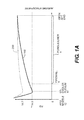
- FIG. 1A is a graphic illustration of the pressure profile in the ITM 100.
- the Y axis is the absolute pressure that ranges from zero to ambient pressure of 14.7 PSI.
- the X axis is the axial distance from the APU nozzle 13 to the open aft end 7.
- surge bleed air exiting the surge bleed air plenum 99 located near the oil cooler plenum 17 periodically adds air volume thereby increasing back pressure in the oil cooler plenum 17.
- little or no cooling air passes through the oil cooler 10, thereby degrading its effectiveness.
- the ITM comprises a tail cone defining a conical backing cavity, the conical backing cavity having a large forward end and a narrow aft end and a porous exhaust liner with a first end and a second end, the first end coupled to an oil cooler eductor discharge plenum of a gas turbine engine and a second end discharging to atmosphere via the narrow aft end of the conical backing cavity.
- the ITM further comprises a bleed air discharge conduit configured to discharge pressurized bleed air from the one or more gas turbine engines into the conical backing cavity and a firewall bulkhead defining the large forward end of the conical backing cavity, defining a first aperture passing the cylindrical porous exhaust liner and defining a second aperture passing the bleed air discharge conduit, the firewall bulkhead extending radially from both of the cylindrical porous exhaust liner and the bleed air discharge conduit.
- a method for minimizing noise generated while discharging pressurized air from one or more aircraft gas turbine engines comprising creating a conical backing cavity defined by a tail cone of an aircraft having a large forward end and a narrow aft end venting to an ambient atmosphere, wherein the large forward end is defined by a firewall bulkhead and inserting a porous exhaust liner comprising a first end and a second end through the conical backing cavity, the porous exhaust liner extending from the narrow aft end of the tail cone through an aperture in the firewall bulkhead, the first end extending through the aperture in the firewall bulkhead and the second end terminating at the narrow aft end of the conical backing cavity.
- the method further comprises inserting a pressurized air discharge conduit through a second aperture in the firewall bulkhead into the conical backing cavity and discharging pressurized air into the large forward end of the conical backing cavity. Any pressure increase from the pressurized air discharged into the conical backing cavity is immediately and partially dissipated by the relatively large size of the conical backing cavity and the pressure of the pressurized air is further reduced as the pressurized air flows through the porous exhaust liner and is discharged to the ambient atmosphere via its second end.
- FIG. 1 is a simplified cross sectional diagram of an existing integrated tailcone muffler (ITM);
- FIG. 1A is a graph of the pressure levels existing between the APU exhaust nozzle and the open aft end of the porous exhaust liner.
- FIGs. 2-9 are simplified cross sectional diagrams of various exemplary embodiments of an ITM as disclosed herein below.
- FIG. 2 is a simplified cross sectional view of an exemplary embodiment of an improved ITM 100'.
- the surge bleed air plenum 99 shown in FIG. 1 is removed and a surge bleed air discharge pipe 8 is routed to penetrate the firewall bulkhead 6 at a point radially removed from the oil cooler plenum 17.
- the bleed air is discharged into the backing cavity 5 of the tailcone 2.
- the multiple APUs may share the same oil cooler plenum or may exhaust to the ambient atmosphere via separate oil cooler plenums and separate porous exhaust liners 4.
- Diffuser A is a conical, flared fitting that resembles a funnel.
- Diffuser B may be the diffuser A with the open end capped by a bulbous porous or a perforated cover/cap.
- Diffuser C may also be the diffuser A with a plate or a diverter device arranged perpendicularly to the bleed air discharge pipe 8 and spaced away from the diffuser such that air impinges on the under surface of the plate and escapes radially from the diffuser.
- the diffusers may take other numerous alternative forms such as a perforated pipe extending into, or through, the backing cavity 5.
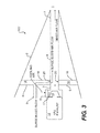
- FIG. 3 is a simplified cross sectional view of another exemplary embodiment of the ITM 100'.
- FIG. 3 is essentially the same as the ITM 100' of FIG. 2 with the exception that a hard baffle 16 has been added at a specific axial distance aft of the firewall bulkhead 6 to create a surge bleed plenum 18.
- the surge bleed plenum 18 may reduce the surge bleed air noise signature relative to the embodiments of FIG. 2 .
- the axial distance between the firewall bulkhead 6 and the hard baffle 16 may be any suitable distance commensurate with the volume and pressure of the bleed air to be discharged and the size of the diffuser (A-C), if any, such that a significant back pressure does not form in the oil cooler plenum 17.
- the hard baffle 16 may be sealedly attached to the porous exhaust liner 4 or may only circumferentially allow the porous exhaust liner to pass therethrough, as may be found most advantageous in a particular application.
- the outer perimeter of the hard baffle 16 may be sealedly attached to the tail cone 2, or it may not to allow surge bleed air to escape around its periphery into the backing cavity 5.
- the length of the porous exhaust liner 4 extending between the firewall bulkhead 6 and the hard baffle 16 may be constructed of perforated sheet metal 20 (i.e., perforate) with a plurality of various-shaped holes penetrating therethrough of a suitable size as to accommodate the volume and pressure of the surge bleed air when periodically discharged.
- the length of the porous exhaust liner 4 between the firewall bulkhead 6 and the hard baffle 16 may be constructed of a "linear" liner such as compressed wire sheeting (e.g., poroplate ® ) or compressed metallic shapes (e.g., Feltmetal), or constructed from both perforate 20 and a "linear" liner.
- FIG. 4 is a simplified cross sectional view of an exemplary embodiment of an ITM 100'.
- FIG. 4 is essentially the same as the ITM 100' of FIG. 3 with the exception that the hard baffle 16 has been radially truncated to create a smaller surge bleed plenum 18.
- the smaller surge bleed plenum 18 may reduce weight and any surge bleed air noise signature relative to the embodiments of FIG. 3 .
- the outer circumferential edge of the hard baffle 16 may be sealedly attached to the firewall bulkhead 6.
- the hard baffle 16 may be loosely or flexibly fitted to the firewall bulkhead 6 to allow surge bleed air to escape into the backing cavity 5 around the circumferential edge of the hard baffle 16.
- the circumferential edge of the hard baffle 16 may also contain perforations or passages to allow some surge bleed air to escape into the backing cavity 5.
- FIG. 5 is a simplified cross sectional view of another exemplary embodiment of an ITM 100'.
- FIG. 5 is essentially the same as the ITM of FIG. 3 and illustrates features of the porous exhaust liner 4 that may be selectively incorporated into any of the previously described embodiments.
- an annular opening 30 has been added to the porous exhaust liner 4 proximate to, and downstream from, the firewall bulkhead 6.
- the placement of the annular opening may also be simultaneously upstream of a hard baffle 16 (e.g., See, FIG. 3 ), if any.
- the purpose of the annular opening 30 is to facilitate the surge bleed air flow from the bleed air discharge pipe 8 into the porous exhaust liner 4, for improved sound abatement.
- FIG. 6 is a simplified cross sectional view of another exemplary embodiment of an ITM 100'.
- FIG. 6 is essentially the same as the ITM of FIG. 5 and is presented to illustrate features of the porous exhaust liner 4 that may be selectively incorporated in any of the previously described embodiments.
- the annular opening 30 has been replaced with a section containing angled effusion holes 35 added to the porous exhaust liner 4 proximate to and downstream from the firewall bulkhead 6.
- the placement of the annular effusion holes 35 may also be simultaneously upstream of the hard baffle 16, if any.
- the purpose of the angular effusion holes 35 is to directionally introduce the surge air flow from the bleed air discharge pipe 8 into the porous exhaust liner 4 as may be desired, but in a more controlled manner.
- the angular effusion holes 35 are angled inward and toward the rear of the porous exhaust liner 4 to allow surge air to more freely exit the backing cavity 5 in the rearward direction but to make it more difficult for mixed airflow to enter the backing cavity 5 in the reverse direction.
- FIG. 7 is a simplified cross sectional view of another exemplary embodiment of an ITM 100'.
- FIG. 7 is essentially the same as the ITM of FIG. 5 and illustrates an exemplary embodiment including the annular opening 30 of FIG. 5 located between the firewall bulkhead 6 and the hard baffle 16.
- the annular opening 30 allows the surge bleed air discharge to freely enter the porous exhaust liner 4 from the surge bleed plenum 18 and possibly into the backing cavity 5 through the porous exhaust liner 4.
- FIG. 8 is a simplified cross sectional view of an exemplary embodiment of an ITM 100'.
- FIG. 8 is essentially the same as the ITM of FIG. 5 and illustrates another exemplary embodiment including the annular opening 30 of FIG. 5 located between the firewall bulkhead 6 and the hard baffle 16.
- the primary difference between FIGs. 5 and 8 is that in FIG. 5 the bleed air discharge pipe 8 discharges directly into the backing cavity 5, while in FIG. 8 the diffuser "A" discharges into the porous exhaust liner 4 via an annular opening 30.
- FIG. 9 is a simplified cross sectional view of an exemplary embodiment of an ITM 100'.
- FIG. 8 is essentially the same as the ITM of FIG. 8 and illustrates another exemplary embodiment without the annular opening 30.
- the primary difference between FIGs. 8 and 9 is that in FIG. 9 the bleed air discharge pipe 8 discharges directly into the porous exhaust liner 4 at a point much further aft from the firewall bulkhead 6, while in FIG. 8 the diffuser "A" (See Fig. 2 ) discharges just aft of the firewall bulkhead 6.
- the difference in axial location along the porous exhaust liner 4 is dependent on a trade off between noise level concerns, where discharge into the porous exhaust liner 4 is preferably just aft of the firewall bulkhead 6, and back pressure concerns in the oil cooler plenum, which would be advantageously mitigated with the surge air discharge being located further aft.
Landscapes
- Engineering & Computer Science (AREA)
- Chemical & Material Sciences (AREA)
- Combustion & Propulsion (AREA)
- Mechanical Engineering (AREA)
- General Engineering & Computer Science (AREA)
- Exhaust Silencers (AREA)
Applications Claiming Priority (1)
| Application Number | Priority Date | Filing Date | Title |
|---|---|---|---|
| US13/097,904 US8235170B1 (en) | 2011-04-29 | 2011-04-29 | Integrated tailcone muffler assemblies and methods |
Publications (1)
| Publication Number | Publication Date |
|---|---|
| EP2518295A2 true EP2518295A2 (de) | 2012-10-31 |
Family
ID=45992096
Family Applications (1)
| Application Number | Title | Priority Date | Filing Date |
|---|---|---|---|
| EP12164625A Withdrawn EP2518295A2 (de) | 2011-04-29 | 2012-04-18 | Anordnung eines integrierten Austrittskonus-Schalldämpfers und Verfahren zur Anwendung desselben |
Country Status (3)
| Country | Link |
|---|---|
| US (1) | US8235170B1 (de) |
| EP (1) | EP2518295A2 (de) |
| CN (1) | CN102758667A (de) |
Cited By (1)
| Publication number | Priority date | Publication date | Assignee | Title |
|---|---|---|---|---|
| EP4571073A3 (de) * | 2023-12-15 | 2025-08-13 | RTX Corporation | Belüftungssystem für flugzeugantriebssystem |
Families Citing this family (10)
| Publication number | Priority date | Publication date | Assignee | Title |
|---|---|---|---|---|
| US8556027B2 (en) * | 2011-06-28 | 2013-10-15 | United Technologies Corporation | Eductor exhaust silencer assembly with bypass gasflow |
| US8893508B2 (en) * | 2012-05-30 | 2014-11-25 | Honeywell International Inc. | Systems and methods for directing cooling flow into the surge plenum of an exhaust eductor cooling system |
| US10184372B2 (en) * | 2016-05-23 | 2019-01-22 | Honeywell International Inc. | Exhaust systems and methods for gas turbine engine |
| FR3054858B1 (fr) * | 2016-08-03 | 2018-09-07 | Safran Aircraft Engines | Turbomachine comportant un dispositif d'entrainement d'un equipement dispose dans le cone d'echappement |
| US10994449B2 (en) * | 2017-02-13 | 2021-05-04 | Lightweight Labs, Llc | Air impingement device, system and method for thermal processing and consolidation |
| US10794402B2 (en) | 2017-10-31 | 2020-10-06 | General Electric Company | Ejector and a turbo-machine having an ejector |
| US11078837B2 (en) | 2019-02-06 | 2021-08-03 | Raytheon Technologies Corporation | Engine bleed air ducting into heat exchanger |
| US10875660B1 (en) * | 2019-06-05 | 2020-12-29 | Pratt & Whitney Canada Corp. | Aircraft power plant |
| US10967983B2 (en) * | 2019-06-05 | 2021-04-06 | Pratt & Whitney Canada Corp. | Aircraft power plant |
| CN111120656B (zh) * | 2019-12-25 | 2022-05-27 | 中国航空工业集团公司西安飞机设计研究所 | 一种进气道防火密封结构 |
Citations (1)
| Publication number | Priority date | Publication date | Assignee | Title |
|---|---|---|---|---|
| US5265408A (en) | 1992-02-13 | 1993-11-30 | Allied-Signal Inc. | Exhaust eductor cooling system |
Family Cites Families (15)
| Publication number | Priority date | Publication date | Assignee | Title |
|---|---|---|---|---|
| US3575261A (en) | 1969-10-24 | 1971-04-20 | Rohr Corp | Fan jet silencer with fluid mixture |
| US3826331A (en) | 1972-02-29 | 1974-07-30 | Bolt Beranek & Newman | Method of and apparatus for reducing sound generated by surfaces in fluid jet streams and the like |
| GB1409887A (en) | 1972-12-18 | 1975-10-15 | Secr Defence | Aircraft gas turbine engine noise suppression |
| US3998047A (en) | 1975-04-18 | 1976-12-21 | The United States Of America As Represented By The United States Energy Research And Development Administration | Method and apparatus for preventing overspeed in a gas turbine |
| US4214441A (en) * | 1978-09-12 | 1980-07-29 | The United States Of America As Represented By The Secretary Of The Navy | Infrared suppressor device |
| US5097656A (en) | 1989-12-29 | 1992-03-24 | Sundstrand Corporation | Dual purpose apparatus for turbine engine exhaust noise and anti-surge air noise reduction |
| US5782082A (en) * | 1996-06-13 | 1998-07-21 | The Boeing Company | Aircraft engine acoustic liner |
| US6973790B2 (en) * | 2000-12-06 | 2005-12-13 | Mitsubishi Heavy Industries, Ltd. | Gas turbine combustor, gas turbine, and jet engine |
| US6615576B2 (en) * | 2001-03-29 | 2003-09-09 | Honeywell International Inc. | Tortuous path quiet exhaust eductor system |
| US6571549B1 (en) | 2001-10-05 | 2003-06-03 | The United States Of America As Represented By The Secretary Of The Air Force | Jet noise suppressor |
| US7055329B2 (en) | 2003-03-31 | 2006-06-06 | General Electric Company | Method and apparatus for noise attenuation for gas turbine engines using at least one synthetic jet actuator for injecting air |
| US7418813B2 (en) * | 2004-12-27 | 2008-09-02 | General Electric Company | Gas turbine engine exhaust nozzle including an infrared suppression system having a plurality of U-shaped blocking fins and method of assembling said exhaut nozzle |
| CN2861499Y (zh) * | 2005-12-31 | 2007-01-24 | 烟台首钢东星备件修复分公司 | 复式滤波消音器 |
| US20080057848A1 (en) * | 2006-08-31 | 2008-03-06 | Honeywell International, Inc. | Venturi gate valve assembly for an auxiliary power unit |
| US7578369B2 (en) * | 2007-09-25 | 2009-08-25 | Hamilton Sundstrand Corporation | Mixed-flow exhaust silencer assembly |
-
2011
- 2011-04-29 US US13/097,904 patent/US8235170B1/en not_active Expired - Fee Related
-
2012
- 2012-04-18 EP EP12164625A patent/EP2518295A2/de not_active Withdrawn
- 2012-04-27 CN CN2012101276221A patent/CN102758667A/zh active Pending
Patent Citations (1)
| Publication number | Priority date | Publication date | Assignee | Title |
|---|---|---|---|---|
| US5265408A (en) | 1992-02-13 | 1993-11-30 | Allied-Signal Inc. | Exhaust eductor cooling system |
Cited By (1)
| Publication number | Priority date | Publication date | Assignee | Title |
|---|---|---|---|---|
| EP4571073A3 (de) * | 2023-12-15 | 2025-08-13 | RTX Corporation | Belüftungssystem für flugzeugantriebssystem |
Also Published As
| Publication number | Publication date |
|---|---|
| CN102758667A (zh) | 2012-10-31 |
| US8235170B1 (en) | 2012-08-07 |
Similar Documents
| Publication | Publication Date | Title |
|---|---|---|
| US8235170B1 (en) | Integrated tailcone muffler assemblies and methods | |
| US8550208B1 (en) | High pressure muffling devices | |
| US8596568B2 (en) | Exhaust silencer with baffles | |
| US8430202B1 (en) | Compact high-pressure exhaust muffling devices | |
| US7578369B2 (en) | Mixed-flow exhaust silencer assembly | |
| US9316111B2 (en) | Active turbine tip clearance control system | |
| US6094907A (en) | Jet engine and method for reducing jet engine noise by reducing nacelle boundary layer thickness | |
| EP0968918B1 (de) | Passives Kühlsystem zur Kühlung der Hilfskrafteinheit eines Flugzeuges | |
| US7730995B2 (en) | Acoustic apparatus | |
| RU2411389C2 (ru) | Двухконтурный газотурбинный двигатель, снабженный предварительным охладителем | |
| US10486821B2 (en) | Jet engine anti-icing and noise-attenuating air inlets | |
| US10184372B2 (en) | Exhaust systems and methods for gas turbine engine | |
| US8556027B2 (en) | Eductor exhaust silencer assembly with bypass gasflow | |
| US7350619B2 (en) | Auxiliary power unit exhaust duct with muffler incorporating an externally replaceable acoustic liner | |
| US20080236939A1 (en) | Exhaust silencer assembly | |
| US9410485B2 (en) | Composite panel having a built-in duct | |
| EP2905227B1 (de) | Verzweigte Leitungen mit Sammelkammern zur Stabilisierung der Strömung durch diese und Auspuffsysteme damit | |
| EP3828078A1 (de) | Gasturbinentriebwerk, dessen triebwerksgondel und verfahren zum betrieb eines gasturbinentriebwerks | |
| EP1748177A1 (de) | Kompakte, gewichtsreduzierte Anordnung des Sammelraumes des Ölkühlers und des Sammelraumes der Abblaseluft in einem Abgasejektor |
Legal Events
| Date | Code | Title | Description |
|---|---|---|---|
| PUAI | Public reference made under article 153(3) epc to a published international application that has entered the european phase |
Free format text: ORIGINAL CODE: 0009012 |
|
| 17P | Request for examination filed |
Effective date: 20120418 |
|
| AK | Designated contracting states |
Kind code of ref document: A2 Designated state(s): AL AT BE BG CH CY CZ DE DK EE ES FI FR GB GR HR HU IE IS IT LI LT LU LV MC MK MT NL NO PL PT RO RS SE SI SK SM TR |
|
| AX | Request for extension of the european patent |
Extension state: BA ME |
|
| STAA | Information on the status of an ep patent application or granted ep patent |
Free format text: STATUS: THE APPLICATION HAS BEEN WITHDRAWN |
|
| 18W | Application withdrawn |
Effective date: 20150928 |