EP2518345A2 - Recouvrement pour la réception d'un véhicule sur rail profilé - Google Patents
Recouvrement pour la réception d'un véhicule sur rail profilé Download PDFInfo
- Publication number
- EP2518345A2 EP2518345A2 EP12165001A EP12165001A EP2518345A2 EP 2518345 A2 EP2518345 A2 EP 2518345A2 EP 12165001 A EP12165001 A EP 12165001A EP 12165001 A EP12165001 A EP 12165001A EP 2518345 A2 EP2518345 A2 EP 2518345A2
- Authority
- EP
- European Patent Office
- Prior art keywords
- cover
- rail carriage
- carriage
- profile rail
- profiled rail
- Prior art date
- Legal status (The legal status is an assumption and is not a legal conclusion. Google has not performed a legal analysis and makes no representation as to the accuracy of the status listed.)
- Granted
Links
Images



Classifications
-
- F—MECHANICAL ENGINEERING; LIGHTING; HEATING; WEAPONS; BLASTING
- F16—ENGINEERING ELEMENTS AND UNITS; GENERAL MEASURES FOR PRODUCING AND MAINTAINING EFFECTIVE FUNCTIONING OF MACHINES OR INSTALLATIONS; THERMAL INSULATION IN GENERAL
- F16C—SHAFTS; FLEXIBLE SHAFTS; ELEMENTS OR CRANKSHAFT MECHANISMS; ROTARY BODIES OTHER THAN GEARING ELEMENTS; BEARINGS
- F16C29/00—Bearings for parts moving only linearly
- F16C29/04—Ball or roller bearings
- F16C29/06—Ball or roller bearings in which the rolling bodies circulate partly without carrying load
- F16C29/0602—Details of the bearing body or carriage or parts thereof, e.g. methods for manufacturing or assembly
-
- F—MECHANICAL ENGINEERING; LIGHTING; HEATING; WEAPONS; BLASTING
- F16—ENGINEERING ELEMENTS AND UNITS; GENERAL MEASURES FOR PRODUCING AND MAINTAINING EFFECTIVE FUNCTIONING OF MACHINES OR INSTALLATIONS; THERMAL INSULATION IN GENERAL
- F16C—SHAFTS; FLEXIBLE SHAFTS; ELEMENTS OR CRANKSHAFT MECHANISMS; ROTARY BODIES OTHER THAN GEARING ELEMENTS; BEARINGS
- F16C29/00—Bearings for parts moving only linearly
- F16C29/008—Systems with a plurality of bearings, e.g. four carriages supporting a slide on two parallel rails
-
- F—MECHANICAL ENGINEERING; LIGHTING; HEATING; WEAPONS; BLASTING
- F16—ENGINEERING ELEMENTS AND UNITS; GENERAL MEASURES FOR PRODUCING AND MAINTAINING EFFECTIVE FUNCTIONING OF MACHINES OR INSTALLATIONS; THERMAL INSULATION IN GENERAL
- F16C—SHAFTS; FLEXIBLE SHAFTS; ELEMENTS OR CRANKSHAFT MECHANISMS; ROTARY BODIES OTHER THAN GEARING ELEMENTS; BEARINGS
- F16C29/00—Bearings for parts moving only linearly
- F16C29/04—Ball or roller bearings
- F16C29/06—Ball or roller bearings in which the rolling bodies circulate partly without carrying load
- F16C29/0633—Ball or roller bearings in which the rolling bodies circulate partly without carrying load with a bearing body defining a U-shaped carriage, i.e. surrounding a guide rail or track on three sides
- F16C29/0635—Ball or roller bearings in which the rolling bodies circulate partly without carrying load with a bearing body defining a U-shaped carriage, i.e. surrounding a guide rail or track on three sides whereby the return paths are provided as bores in a main body of the U-shaped carriage, e.g. the main body of the U-shaped carriage is a single part with end caps provided at each end
- F16C29/0638—Ball or roller bearings in which the rolling bodies circulate partly without carrying load with a bearing body defining a U-shaped carriage, i.e. surrounding a guide rail or track on three sides whereby the return paths are provided as bores in a main body of the U-shaped carriage, e.g. the main body of the U-shaped carriage is a single part with end caps provided at each end with balls
- F16C29/0642—Ball or roller bearings in which the rolling bodies circulate partly without carrying load with a bearing body defining a U-shaped carriage, i.e. surrounding a guide rail or track on three sides whereby the return paths are provided as bores in a main body of the U-shaped carriage, e.g. the main body of the U-shaped carriage is a single part with end caps provided at each end with balls with four rows of balls
- F16C29/0647—Ball or roller bearings in which the rolling bodies circulate partly without carrying load with a bearing body defining a U-shaped carriage, i.e. surrounding a guide rail or track on three sides whereby the return paths are provided as bores in a main body of the U-shaped carriage, e.g. the main body of the U-shaped carriage is a single part with end caps provided at each end with balls with four rows of balls with load directions in X-arrangement
-
- F—MECHANICAL ENGINEERING; LIGHTING; HEATING; WEAPONS; BLASTING
- F16—ENGINEERING ELEMENTS AND UNITS; GENERAL MEASURES FOR PRODUCING AND MAINTAINING EFFECTIVE FUNCTIONING OF MACHINES OR INSTALLATIONS; THERMAL INSULATION IN GENERAL
- F16C—SHAFTS; FLEXIBLE SHAFTS; ELEMENTS OR CRANKSHAFT MECHANISMS; ROTARY BODIES OTHER THAN GEARING ELEMENTS; BEARINGS
- F16C29/00—Bearings for parts moving only linearly
- F16C29/08—Arrangements for covering or protecting the ways
- F16C29/084—Arrangements for covering or protecting the ways fixed to the carriage or bearing body movable along the guide rail or track
-
- F—MECHANICAL ENGINEERING; LIGHTING; HEATING; WEAPONS; BLASTING
- F16—ENGINEERING ELEMENTS AND UNITS; GENERAL MEASURES FOR PRODUCING AND MAINTAINING EFFECTIVE FUNCTIONING OF MACHINES OR INSTALLATIONS; THERMAL INSULATION IN GENERAL
- F16C—SHAFTS; FLEXIBLE SHAFTS; ELEMENTS OR CRANKSHAFT MECHANISMS; ROTARY BODIES OTHER THAN GEARING ELEMENTS; BEARINGS
- F16C2300/00—Application independent of particular apparatuses
- F16C2300/02—General use or purpose, i.e. no use, purpose, special adaptation or modification indicated or a wide variety of uses mentioned
-
- F—MECHANICAL ENGINEERING; LIGHTING; HEATING; WEAPONS; BLASTING
- F16—ENGINEERING ELEMENTS AND UNITS; GENERAL MEASURES FOR PRODUCING AND MAINTAINING EFFECTIVE FUNCTIONING OF MACHINES OR INSTALLATIONS; THERMAL INSULATION IN GENERAL
- F16C—SHAFTS; FLEXIBLE SHAFTS; ELEMENTS OR CRANKSHAFT MECHANISMS; ROTARY BODIES OTHER THAN GEARING ELEMENTS; BEARINGS
- F16C29/00—Bearings for parts moving only linearly
- F16C29/08—Arrangements for covering or protecting the ways
- F16C29/084—Arrangements for covering or protecting the ways fixed to the carriage or bearing body movable along the guide rail or track
- F16C29/086—Seals being essentially U-shaped, e.g. for a U-shaped carriage
Definitions
- Embodiments relate to a cover for receiving a profile rail car.
- a linear guide represents an arrangement which enables the least friction-translatory movement of one or more movable assemblies of a machine along a direction of movement.
- the direction of motion is in many cases a linear path, which is not limited to a straight line in the mathematical sense. Therefore, in the area of linear guides, the terms “linear” and “translational” are often used interchangeably.
- linear guides are typically subdivided into sliding guides or rolling guides, wherein the rolling guides are based on rolling elements being moved between two relatively moving raceways.
- rolling elements are for example balls, cylinders, needles, tons or other rolling elements.
- the linear roller bearings also include profiled rail guides. These encompass so-called profile rail cars, carriages or carriages a guide rail or rail. Profile rail cars therefore often have a substantially U-shaped cross-section.
- the profile rail car is mounted on the guide rail by means of rolling elements.
- the roller bearing linear guides are subdivided into finite and infinite guides.
- the finite linear guides typically have only a limited Stroke along the direction of movement.
- infinite linear guides have, in principle, only a stroke limited by the length of the relevant track or rail in question. Since the rolling elements typically move at half the relative speed of the two components moving relative to each other, this generally requires that the rolling elements must be returned in order to provide limited movement only by the length of the corresponding track or rail.
- Profile rail guides typically represent corresponding infinite guides, so that the corresponding profile rail cars have a corresponding Wälzève Examment.
- Profile rail cars therefore generally comprise at least one load area in which the rolling elements move on a track of the profile rail carriage on the one hand and on a track of the relevant rail or guide rail on the other hand, and a return area in which the rolling elements move substantially opposite to the direction in the load area ,
- At least one deflection region which is arranged between the load region and the return region, ensures the passage of the rolling elements from the load region into the return region.
- corresponding profiled rail carriages furthermore have a second deflecting region which, together with the first-mentioned deflecting region, the load region and the return region, enables a closed rolling body guidance within the profiled rail carriage.
- Profile rail cars and corresponding profile rail guides are used in the variety of application scenarios in which assemblies of a machine are moved relative to each other along a linear path.
- the corresponding linear guides can be exposed to a variety of different environmental conditions.
- linear guides are used, for example, within media that can penetrate into the interior of the profile rail car, and so may adversely affect its functionality or its life adversely. These include, in addition to solids, such as dusty or granular substances, as well as liquid or gaseous media, which could adversely affect its functionality or its useful life due to chemical interactions with the profile rail car or its components.
- profile rail cars are used under environmental conditions that can promote corrosion of the material of the profile rail car.
- the aforementioned solid media for example, penetrate into the profile rail car and get there between the rolling elements and the track of the profile rail or the rail and there lead to a blocking of the rolling element or abrasive effects in the respective career or the respective rolling element.
- An exemplary embodiment of a cover for accommodating a profiled rail carriage in an interior of the cover comprises a first end face and a second end face, which delimit the interior in the direction of movement on a side opposite in a direction of movement of the profiled rail carriage. It further comprises a first side surface and a second side surface, which in opposite in a direction perpendicular to the direction of movement of the profile rail car sides bound the interior in the vertical direction, wherein the end faces each having a recess, and wherein the recesses have a shape, so that a Rail, the recesses may pass at least with a part of its cross-sectional shape to allow a arranged in the interior of profile rail car movement along the rail.
- the cover leaves an upper side open, at least in an assembly region of the profiled rail carriage.
- An exemplary embodiment of a system comprises a profiled rail carriage and such a cover, wherein the profiled rail carriage is arranged in the interior space, and wherein the profiled rail carriage has a component arranged in the direction of movement of the profiled rail carriage with a lubricant reservoir.
- the component has a lubricant opening pointing in the direction of movement so that the lubricant reservoir can be refilled through the lubricant opening, at least one end face of the cover having a further recess, so that the cover is connected to the profile rail carriage via the further recess with a further component which can be introduced into the lubricant opening is.
- Embodiments based on the finding that a protection of a profile rail car is thereby improved, in that it is arranged in the interior of the cover according to an embodiment.
- the end faces in this case each have a recess, which in turn have a shape so that a profile rail can pass the recess in question with at least a portion of its cross-sectional shape to the arranged in the interior profile rail car movement along the rail.
- the cover leaves an upper side open at least in a mounting region of the profile rail car. This cover thus provided a protection that prevents, but at least reduces, the immediate impact of an environmental impact on the profile rail car.
- the cover can leave the top completely open, so that a more flexible integration can take place in an optionally existing module, since the assembly concerned may not be structurally modified by a subsequent attachment of a cover according to an embodiment.
- At least one of the recesses in the end faces may have a sealing element which is designed to seal the end face against the profile rail, in order to reduce or prevent penetration of a gaseous, a liquid or a solid medium into the interior space. This makes it possible to protect the profile rail car against contamination or corrosion protection to improve or to achieve an additional seal against the rail. As a result, a stripping effect can be achieved.
- the cover may have at least 80% of an overall surface area of the interior side of the first side surface, the second side surface, the first end surface, and the second end surface having an average roughness of less than 100 ⁇ m, a coating, or a finish, wherein the coating comprises, for example, Teflon or enamel.
- the coating comprises, for example, Teflon or enamel.
- an average roughness of less than 80 microns, less than 50 microns, less than 20 microns be provided by less than 10 microns or less than 2 microns. In this way, if appropriate, the cleaning possibility can be made even easier, or else a corrosion protection can be improved, since corresponding media offer a smaller attack surface due to the lower average roughness.
- the cover in the interior space may include a sound absorbing material on at least a portion of the first side surface, the second side surface, the first end side, or the second end side, so that noise generated during operation of the profile railroad car is reduced by the cover. In other words, such embodiments may cause a reduction in noise caused by the operation of the profile rail car.
- a cavity can be foamed on at least a part of said sides.
- a material for example, a melamine resin foam or another foam made of a plastic or an organic compound can be used.
- the cover may be formed such that a profile rail carriage arranged in the interior is protected against a shock from the direction of movement up to a predetermined kinetic energy.
- the predetermined kinetic energy can at Embodiments of a kinetic energy corresponding to be given by a total mass of the cover, the profile rail car and a maximum allowable load of the profile rail car at one-tenth of a maximum allowable for the profile rail car speed.
- the predetermined kinetic energy may also correspond to a kinetic energy given at one fifth, one quarter, one third or one half of the maximum allowable speed for the profile rail car.
- the cover on at least one of the end faces or at least one of the side surfaces may have an energy absorbing structure which is designed to absorb a kinetic energy which does not exceed the predetermined kinetic energy.
- the structure may in this case be designed such that the energy is at least partially converted into an elastic, a plastic or a thermal energy.
- the first side surface, the second side surface, the first end surface or the second end surface may be formed such that a radiation having a predetermined frequency is at least partially or completely reflected.
- This may, for example, be an infrared radiation and / or a visible radiation.
- a hot object or other hot source eg, an oven.
- the cover may further have a bottom surface opposite to the top and bounded along a second direction, which is perpendicular to the direction of movement of the profile rail car and different from the aforementioned vertical direction, the interior.
- the underside surface may in this case have a longitudinal recess, so that the profile rail can at least partially pass through this recess in order to allow the profile rail carriage arranged in the interior to move along the profile rail.
- the lower side surface may have a first partial surface and a second partial surface, wherein the first partial surface is connected to the first side surface, the first end surface and a second end surface, and wherein the second partial surface is connected to the second side surface, the first end surface or the second end surface is.
- the cover may be further configured to receive another profile rail carriage in the interior. This makes it possible to at least partially surround more than one profile rail car by a common cover, so that, for example, by a simple modular structure with several profile rail cars a higher load system is created, which is at least partially surrounded by the common cover, without gaps between several Covers arise.
- the cover can be made in one piece or in one piece, so that optionally gaps can be reduced or avoided, which may optionally positively influence the aforementioned properties.
- At least one of the side surfaces may have a lateral recess or a predetermined partial surface, wherein the partial surface is at least partially surrounded by a material-weakened region, so that the partial surface is removable in order to form the lateral recess.
- the cover may be geometrically formed such that a flow characteristic of the profile rail car is improved, so that a movement in a gaseous, liquid or solid medium has a lower friction on the medium result. This makes it possible to improve the Umströmungseigenschaften and thus to achieve the design of the profile rail car.
- the cover has a further recess in at least one of the end faces, so that a simple mounting of the cover on the profile rail carriage is possible via this further recess.
- the profiled rail carriage has a component arranged in the direction of movement with a lubricant reservoir, wherein the component has a lubricant opening pointing in the direction of movement, so that the lubricant reservoir can be refilled through the lubricant opening.
- the further recess is in this case arranged such that the cover is connected via this further recess with an insertable into the lubricant opening further component with the profile rail car.
- the further component may be, for example, a grease nipple or a threaded pin.
- this may further comprise a second profiled rail car.
- the profiled rail carriage is in this case connected via the further component with the first end face of the cover.
- the second profiled rail carriage has - corresponding to the first profiled rail carriage - arranged in the direction of movement of the second profiled rail car second component with a lubricant reservoir, wherein the second component also has a pointing in the direction of movement or against the direction of movement lubricant opening, so through the lubricant opening, the lubricant reservoir refillable is.
- the second end face of the cover in this case has a second further recess, so that the cover is connected via the second further recess with a second further component which can be introduced into the lubricant opening of the second component with the second profiled rail carriage.
- Embodiments of a cover can in this case comprise a metal, a metal alloy, that is, for example, a niroboard, a stainless steel, a steel or a plastic or consist of this.
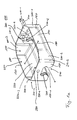
- Fig. 1 shows a cover 100 according to an embodiment.
- the cover 100 has an inner space 110, which serves to receive a profile rail car, which in Fig.1 not shown.
- the cover 100 has a first end face 120 and a second end face 130, which delimit the inner space 110 in the direction of movement 140 on sides which are opposite in a direction of movement 140 of the profiled rail carriage.
- the two end faces 120, 130 in this case each have a recess 150. More specifically, the first end face 120 has a first recess 150-1 and the second end face 130 has a further recess 150-2, which are arranged along the direction of movement 140.
- the direction of movement 140 thus represents the direction that connects the two recesses 150 in the two end faces 120, 130 with each other.
- the recesses 150 have a shape, so that a rail, the in Fig.1 not shown, the recesses 150 may pass at least with part of its cross-sectional shape to allow the arranged in the interior profile rail car to move along the corresponding rail.
- these also have a shape that corresponds to a part of the cross-sectional shape of the rail such that between the recesses 150 and the rail, a gap is formed with a maximum gap size, which can assume different values in different embodiments.
- the gap dimension is in various embodiments typically not more than 10 mm, 5 mm, 2 mm, 1 mm or 500 microns. As a result, a gap seal between the cover 100 and the in Fig. 1 not shown profiled rail are formed.
- the cover 100 further includes a first side surface 160 and a second side surface 170 that are perpendicular to a direction 180 that is perpendicular to the direction of movement 140 of the profile rail car and that define the interior space 110 in the direction 180.
- the first and the second Side surface 160, 170 each have a central surface 190, which are connected via intermediate surfaces 200, more precisely, intermediate surfaces 200-1, 200-2, 200-3 and 200-4 with the end faces 120, 130.
- the intermediate surfaces 200 are in this case in the respective side surfaces 160, 170 includes and connected to the end faces 120, 130 via rounding regions 210.
- rounding areas 210 often have a radius of curvature that is typically in the range between 0.5 mm and 50 mm, depending on the size of the cover 100 and the profile rail car to be accommodated therein. However, embodiments also include those for larger or smaller profile rail cars.
- the cover 100 further includes a bottom surface 220, which in the in Fig. 1 but shown embodiment of a cover has a first lower partial surface 230-1 and a second lower partial surface 230-2, which in the in Fig. 1a shown by the first side surface 160 is hidden.
- the first lower partial surface 230-1 is in this case mechanically connected to the second side surface 170, while the second lower partial surface 230-2 is connected to the second lateral surface 170.
- a longitudinal recess 240 is formed, which extends completely along the direction of movement 140 through the cover 100.
- the longitudinal recess 240 in this case has a width in the direction 180, so that between the cover 100 and the rail, which in Fig. 1a not shown, at most a gap is formed having the aforementioned maximum gap.
- the cover 100 may also be implemented without a corresponding longitudinal arrangement 240 if, for example, the cover 100 can completely enclose the profile rail.
- the underside surface 210 limits the interior space 110 in a direction that is both perpendicular to the movement direction 140 and to the direction 180. In embodiments, this direction may possibly also only differ from the direction 180.
- a top 250 located on an opposite side of the underside 220 is left open by the cover 100 at least in a mounting area of the profile rail car.
- the cover 100 Even fully open the top, which may make a subsequent modification of other components of the machine when retrofitting a profile rail car with a cover 100 according to an embodiment unnecessary.
- a cover 100 further has at both recesses 150 in the two end faces 120, 130 each have a receptacle 260 for a sealing element that in Fig. 1a but not shown.
- the sealing elements are in this case designed to seal the respective end face 120, 130 against the profile rail so as to reduce or even completely prevent penetration of a gaseous, liquid or solid medium into the interior 110.
- the receptacles 260 are designed in the form of a double-walled area, between which the corresponding sealing elements are einbringbaren.
- sealing elements on the end faces 120, 130 may also be attached in other ways. It is for example possible to glue a corresponding sealing element with the relevant end face 120, 130 or to screw. Likewise, it is possible to fasten such a sealing element in the region of the corresponding end faces 120, 130 by means of another connection method, that is, for example, a clamp.
- the gap seal produced on the basis of the above-described possibility of implementing a gap with a small gap dimension can be supplemented or replaced by a wiper seal inserted, for example.
- a seal thus represents an example of a circumferential scraper, which can also be incorporated to achieve an additional wiping effect.
- sealing elements for example, seals made of a rubber or a plastic as well as more complex seals, so for example cassette seals.
- a cover 100 both recesses 150-1 and 150-2 in both end faces 120, 130 each have a receptacle 260 for a sealing element
- a corresponding receptacle or a sealing element at any end face only on one of the two end faces 120, 130 or to provide both.
- these sealing elements or their associated receptacles 260 are optional components.
- a cover 100 for a corresponding profiled rail car it is basically possible to use very different attachment methods.
- embodiments can be connected to a corresponding profiled rail carriage by means of non-positive, positive or even material-locking connections. If, for example, a profile rail car already has an outwardly guided structure, this can optionally be used to connect a cover or hood 100 according to an exemplary embodiment to the profile rail car. If, for example, the profile rail car has an outwardly guided lubrication nipple, it is possible, for example, to fasten the cover to the profile rail carriage by means of this.
- the in Fig. 1a shown embodiment on both end faces 120, 130 each have a further recess 270 which are formed to the cover 100 with the in Fig. 1a not shown profiled rail car to make mechanically connectable.
- the cover 100 in each case in a material-reinforced region 280 of the first end face 120 has a further recess 270-1 in the form of a bore and in the second end face 130 also in a corresponding material reinforced area a second further recess 270-2 in the form of a Hole on.
- these two other recesses 270 are just designed such that they can be screwed with a lubricating nipple or with a threaded pin with the profile rail car. Of course, however, it is also possible to otherwise mechanically connect the cover 100 with the profiled rail car.
- the hood or cover 100 which can be "slipped over" the profiled rail car, may in this case comprise a material or be completely made of this, which may be, for example, a metal, a metal alloy, a steel (eg stainless steel). , a sheet metal (eg Niroblech), a plastic or a plastic acts.
- the cover can also be painted, coated or metal coated.
- a coating may comprise, for example, Teflon or enamel.
- Such a coating or painting is typically applied to the sides facing away from the interior of the first end face 120, the second end face 130, the first side face 160, the second side face 170 and the bottom face 220, provided the corresponding surfaces, ie in particular the bottom face, are implemented.
- the relevant pages typically have the corresponding coating or coating on at least 80% of a surface of the individual pages concerned.
- the proportion of the total area may also be higher, for example at 90%, at least 95% or at the complete surface.
- the relevant surfaces in such a way that they have an average roughness of less than 100 ⁇ m, in other embodiments less than 80 ⁇ m, less than 50 ⁇ m or even less than 20 ⁇ m.
- the cover can be provided with a uniform surface, so that adhesion of dirt, solid or liquid media is thereby prevented or at least reduced, which can lead to a simpler cleaning of the profile rail car or its cover 100.
- This can be advantageous, for example, in the food sector or also in the animal feed sector and is frequently summarized under the heading of hygienic design (hygenic design).
- hygienic design hygenic design
- corrosion protection can be achieved by an appropriate choice of material or a corresponding coating or coating of the cover 100, so that it may not be necessary to resort to expensive special steels (eg stainless steels) during the production of the profile rail wagon.
- the cover 100 can thus be designed to form a corrosion protection for the profiled rail carriage.
- such a cover can replace or at least partially save the costly use of stainless steels or coatings in profile rail cars.
- a heat protection for plastic parts or other sensitive parts of the profile rail car can be realized or improved if it passes, for example, at a hot spring, that is, at a hot oven or other radiation source.
- a cover 100, the first side surface 160, the second side surface 170, the first end surface 120 or the second end surface 130 may be formed such that radiation having a predetermined frequency is at least partially reflected. This can be an infrared radiation and / or a visible radiation, to name only two examples.
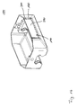
- Fig. 1b shows a further embodiment of a cover 100, which differs from the in Fig. 1a shown differs only in a single aspect. While at the in Fig. 1a shown cover 100, the central surface 190 of the first side surface 160 has no special structure, this has in the in Fig. 1b
- a predetermined partial surface 290 which is at least partially surrounded by a material-weakened region 300, so that the partial surface 290 is removable, to form a lateral recess.
- the material-weakened region 300 can be implemented, for example, by diluting a wall thickness of the cover 100 in this region.
- the cover 100 may have a groove or groove in this region, so that the predetermined partial surface 290 can be broken out of the cover 100.
- the material-weakened region 300 may likewise be formed by means of a perforation or another material weakening, that is to say, for example, by a bond.
- the cover 100 could then be made such that the cover 100 already has the lateral recess, but was subsequently closed again with the partial surface 290.
- a partial surface 290 may of course be provided alternatively as well as in addition in the region of the second side surface 170.
- the optional part surface 290 together with the corresponding material-weakened area in embodiments, not on only one of the two side surfaces 160, 170 or on both side surfaces 160, 170 may be provided. So this is also an optional component.
- Such a partial surface 290 can be provided in order to make available after its breaking or removal and the emergence of the corresponding lateral recess a lateral partial surface of the profile rail car arranged in the interior of the cover 100.
- a lateral partial surface of the profiled rail car for example, have a particularly accurate position or a particularly accurate dimensioning or specification.
- Fig.2 shows a perspective view of another embodiment of a cover 100, which differs from the embodiments described above with respect to the configuration of the first and second side surface 160, 170.
- these two side surfaces 160, 170 each have a lateral recess 310. More specifically, in this case, the first side surface 160 has a first lateral recess 310-1 and the second side surface 170 has a second lateral recess 310-2.
- these two lateral recesses 310 allow lateral access to a profile rail car arranged in the inner space 110 of the cover 100. Through these two lateral recesses 310, it is possible to directly access a corresponding lateral part surface of this profile rail car.
- Each of the two lateral recesses 310 may either already be provided as such in the cover 100 or by removing a predetermined part 290, as in connection with Fig. 1b has been explained by a corresponding removal of the surface 290 arise.
- these lateral recesses 310 may be omitted completely or may be implemented and provided only in one of the side surfaces 160, 170 or in both side surfaces 160, 170.
- the side recesses 310 are optional structures.
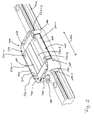
- Figure 3 shows a perspective view of a system 400 with a cover 100 and a profile rail carriage 410, which is arranged on a rail 420.
- Figure 4 shows an exploded view of the in Figure 3 shown system on the rail 420.
- the cover 100 used in the system 400 corresponds to FIG Fig. 1a shown cover 100, wherein in contrast to this in the Figures 3 and 4 shown cover 100 in the first side surface 160 has a lateral recess 310-1.
- the cover 100 has in the region of the two recesses 150-1, 150-2 each have a receptacle 260 for a sealing element.
- the system 400 accordingly includes a first seal member 430-1 and a second seal member 430-2 received in the receptacles 260 for the seal members. Due to their location and their profiled shape, which at least partially simulates the shape of the rail 420, are in Fig. 3 neither the two receptacles 260 nor the two sealing elements 430 can be seen.
- the profiled rail carriage 410 has a body 440 in which both the load area and the return area for the rolling elements are formed.
- rolling elements basically all forms of rolling elements can be used, that is, for example, spherical rolling elements, barrel-shaped rolling elements, cylindrical rolling elements or needle-shaped rolling elements.
- the profiled rail carriage 410 further comprises a first component 450 which is connected along the direction of movement 140 at an end face of the guide carriage 440 with this.
- the first component 450 not only comprises a deflection region for the rolling bodies, which guides them from the load region into the return region or out of the return region into the load region, but also a lubricant reservoir.
- the first component 450 is in the in the Figures 3 and 4 shown system according to an embodiment as an end plate made of a reinforced plastic, which is sealed with a front seal against leakage of the lubricant.
- the first component 450 thus includes a lubricant opening 460, which provides access to the lubricant reservoir of the first component 450.
- a second component 470 which also has a deflection region and optionally another lubricant reservoir comprises. If a corresponding lubricant reservoir is implemented, the second component 470 can furthermore have a lubricant opening which is similar to the lubricant opening 460 of the first component 450. Due to the perspective view in the Figures 3 and 4 however, these are not visible.
- the cover 100 can be connected to the profiled rail carriage 410 by a further component 480 that can be introduced into the lubricant opening 460 of the first component 450.
- the further recess 270 of the cover is formed and positioned on the first end face 120 such that it is aligned with the lubricant opening 460 in a plane perpendicular to the direction of movement 140.
- the further component 480 which engages through the further recess 270 in the first end face 120 into the lubricant opening 460 of the first component 150, is a lubricant nipple, which enables manual relubrication of the guide carriage 440 or the profile rail carriage 410.
- the second component 470 also has with respect to the second component 470 a corresponding lubricant opening, which is also aligned with the further recess 270 of the second end face 130 in a direction perpendicular to the direction of movement 140 level.
- This lubricant opening is mechanically connected via the further recess 270 on the second end face 130 of the cover 100 with a second further component 490.
- the second further component is a threaded pin which does not engage in the optional lubricant reservoir of the second component 400.
- the cover 100 in contrast to the in Fig. 1a shown cover 100 has a side recess 310-1 in the first side surface 160.
- This allows access to a lateral part surface 500 of the profile rail carriage 410.
- the lateral part surface 500 is one of the guide carriage 440.
- This has a particularly precisely specified distance to a recess of the guide carriage 440, in which the rail 420 during the Operating is arranged and at least partially includes the raceway, the load area belongs.
- the lateral face 500 may be one having, for example, a particular surface roughness, orientation, or other equivalent specification.
- Fig. 3 further illustrates that the cover 100 leaves the top open at least in a mounting area 510 of the profile rail cart 410.
- the mounting area 510 is formed by a surface of the guide carriage 440, which in addition to four bores 520 also has two grooves 530.
- the grooves 530 in this case run along the direction of movement 140 and thus enable, for example, a positive connection in a direction perpendicular to the direction of movement 140.
- both the first component 450 and the second component 470 have a smaller width than the guide carriage 440, thus cavities are formed between the cover 100 and the profile rail carriage 410.
- These cavities can be foamed, for example, for noise insulation.
- the cover 100 can thereby act noise insulating by z.
- an additional foam layer is mounted in the interior.
- the cover in the interior at at least a portion of the first side surface 160, the second side surface 170, the first end face 120 or the second end face 130, a sound absorbing material. This may be a corresponding sound absorbing foam of polyurethane or other suitable material.
- a cover 100 makes it possible to provide one of these improvements of the linear unit.
- an improvement of a flow characteristic is possible if, for example, the profile rail car or the system of profiled rail carriage and cover by a gaseous, moving liquid or solid (eg granular) medium.
- the round shapes of the cover 100 reduce a flow resistance value and thus a resistance force acting on the system.
- the new possibilities afforded by the cover 100 according to one embodiment which are in the broadest sense attributable to industrial design, may make it possible to reduce energy consumption in the event of movement along the rail 420.
- the cover 100 may also act as impact protection for plastic deflection regions such as the first and second components 450, 470.
- a profiled rail carriage 410 arranged in the inner space 110 of the cover 100 can be protected against a shock from the direction of movement 140, for example up to a predetermined kinetic energy.
- the cover 100 may be configured to at least partially receive kinetic energy generated by a shock or impact applied to additional reinforcements or other structures attached to the interior surfaces of the cover 100. Depending on the material used for the cover 100 and the corresponding structures so this energy can be at least partially converted into an elastic, plastic or thermal energy.
- the cover 100 may also be partially damaged or destroyed here in order to protect the profiled rail carriage arranged in the interior.
- the predetermined kinetic energy to which a cover 100 according to an embodiment in the case of a corresponding design can protect a profile rail car for example, correspond to a kinetic energy by a total mass of the cover 100, the profile rail carriage 410 and a maximum allowable load of the profile rail car at one tenth of a maximum allowable for the profile rail car speed is given.
- the fraction of the speed may also be higher in relation to the maximum allowable speed, that is, for example, at a fifth, a quarter, a third, a half, or even at the full maximum allowable speed.
- FIGS. 5 and 6 show a further embodiment of a cover 100 and a system 400 with a cover 100 and a profile rail carriage 410.
- Fig. 5 a perspective view
- Fig. 6 a corresponding exploded view.
- the system 400 initially has, in addition to the profiled rail carriage 410, a second profiled rail carriage 540, which is likewise arranged in the inner space 110 of the cover 100.
- the cover 100 is configured to receive another profiled rail carriage 540 in the inner space 110.
- the cover 100 therefore extends along the direction of movement 140 for a greater length than was the case in the previously described embodiments.
- the second profiled rail carriage 540 and the first profiled rail carriage 410 correspond in this case in terms of their structural design in the Figures 3 and 4 shown.
- the cover 100 in contrast to the embodiments described above, no longer integral or designed in one piece, but in several parts. More specifically, the cover 100 includes a first side member 550 that includes at least a portion of the first side surface 160 and a portion of the bottom surface, more specifically, the bottom surface 230-1. The cover 100 further includes a second side member 560 that at least partially surrounds the second side surface 170 and a part of the bottom surface 220, namely, the bottom surface 230-2. In addition, the cover 100 further comprises a first end side member 570, which includes the first end face 120. Correspondingly, on a side facing away from the first end side component 570, the cover 100 has along the movement direction 140 a second end side component 580, which comprises the second end face 130.
- Both end face components 570, 580 have corresponding receptacles (compare, for example, receptacles 260 Fig. 1a to 3 ), in which sealing elements 430-1, 430-2 can be introduced.
- the corresponding receptacles 260 and the sealing elements 430 are optional components which can not be implemented on either of the two end faces, one of the two end faces or on both end faces.
- the two front side members 570, 580 are in the in the Figures 5 and 6 shown embodiment by means of two screws 590 and corresponding holes 600 in the front side members 570, 580 with the two profile rail cars 410, 540 bolted.
- the two end-side components 570, 580 also have further recesses 270-1 and 270-2 which correspond to corresponding lubricant openings of the first component 450 of the profiled rail carriage 410 and of the second component 470 of the second profiled rail carriage 540 in a plane perpendicular to the direction of movement 140 each aligned. So are in the in the Figures 5 and 6 1, the two end-side components 570, 580 are likewise respectively connected to the first profiled rail carriage 410 and the second profiled rail carriage 540 via a first further component 480-1 and a second further component 480-2 in the form of two lubricating nipples.
- the two profiled rail cars 410, 540 in the inner space 110 of the cover 100 at a predetermined distance.
- a gap 610 is formed, which can be used, for example, for structural elements for the two profiled rail cars.
- Embodiments of the present invention in the form of a cover 100 may therefore also possibly meet the need to cover more than one single carriage, for example two or more profile rail cars, on a single guide at a suitable distance.
- This distance is typically predetermined in the case of a particular cover 100, but may be variably configured in various embodiments.
- a cover profile or corresponding side components 550, 560 which are designed to be variable in length in various exemplary embodiments, can be introduced.
- the front side components 570, 580 or also the side components 550, 560 can also have the aforementioned materials.
- these components may comprise a metal, a metal alloy, a steel, a metal sheet or a plastic.
- wipers or seals 430 may also be provided in the retaining caps or end-side components 570, 580 here.
- a system 400 Similar to the one in the Figures 3 and 4 shown embodiment of a system 400 also has in the Figures 5 and 6 shown system lateral recesses 310 in the first side surface 160.
- the first side surface-and thus the first side component 550 has a first lateral recess 310-1 and a second lateral recess 310-2.
- a lateral partial surface 500-1 of the first profiled rail carriage 410 is thus exposed and thus achievable for constructive purposes.
- a second lateral partial surface 500-2 of the second profiled-rail carriage 540 is correspondingly open and accessible for constructive purposes.
- a cover 100 or a system 400 may be formed with a cover 100 for receiving a plurality of profiled rail cars 410, 540 in their inner space 110.
- a corresponding plurality of systems may also be used, in which, for example, a single profiled rail carriage is arranged in each case in a cover 100.
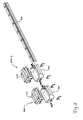
- FIG. 7 Such an arrangement of several embodiments of systems 400 is shown in the perspective view in FIG Fig. 7 and as an exploded view in Fig. 8 shown.
- FIG. 8 shows a first system 400-1 and a second system 400-2, which are arranged on a common rail 420.
- the two systems 400 each comprise a cover 100 according to an exemplary embodiment and a profile rail carriage 410, as previously described in connection with FIGS Figures 3 and 4 have been described.
- covers 100 or profiled rail carriage 410 are by far not limited to this specific embodiment of covers 100 or profiled rail carriage 410.
- very different covers 100 according to exemplary embodiments can also be used here within the framework of corresponding systems 400.
- the number of systems involved that can be grouped together is by no means limited to two. Rather, a variety of corresponding systems can be arranged on a rail.
- Embodiments of the present invention find application in a wide variety of linear systems. With regard to their lengths, profiled rail cars of sizes from a few centimeters (eg 2 cm) up to several meters can be used. For example, the range of permissible loads is correspondingly large.
- exemplary embodiments may also be exposed to different gaseous, liquid or solid media (eg granular media).
- gaseous, liquid or solid media eg granular media
- embodiments can also be used in the food industry or in the feed sector, as well as in the construction machinery sector and other industrial sectors.
- embodiments can be used at different temperatures, pressures or radiations.
- Embodiments may also be used in the field of aggressive chemical, such as corrosive or corrosive media.
Landscapes
- Engineering & Computer Science (AREA)
- General Engineering & Computer Science (AREA)
- Mechanical Engineering (AREA)
- Bearings For Parts Moving Linearly (AREA)
- Seats For Vehicles (AREA)
- Vehicle Interior And Exterior Ornaments, Soundproofing, And Insulation (AREA)
Applications Claiming Priority (1)
| Application Number | Priority Date | Filing Date | Title |
|---|---|---|---|
| DE102011017759.0A DE102011017759B4 (de) | 2011-04-29 | 2011-04-29 | Abdeckung zur Aufnahme eines Profilschienenwagens |
Publications (3)
| Publication Number | Publication Date |
|---|---|
| EP2518345A2 true EP2518345A2 (fr) | 2012-10-31 |
| EP2518345A3 EP2518345A3 (fr) | 2017-07-19 |
| EP2518345B1 EP2518345B1 (fr) | 2018-12-19 |
Family
ID=46044418
Family Applications (1)
| Application Number | Title | Priority Date | Filing Date |
|---|---|---|---|
| EP12165001.4A Not-in-force EP2518345B1 (fr) | 2011-04-29 | 2012-04-20 | Capot de protection pour le logement d'un chariot englobant la glissière profilée d'un palier linéaire |
Country Status (2)
| Country | Link |
|---|---|
| EP (1) | EP2518345B1 (fr) |
| DE (1) | DE102011017759B4 (fr) |
Cited By (1)
| Publication number | Priority date | Publication date | Assignee | Title |
|---|---|---|---|---|
| WO2014079438A1 (fr) * | 2012-11-20 | 2014-05-30 | Schaeffler Technologies AG & Co. KG | Ensemble de guidage linéaire |
Families Citing this family (2)
| Publication number | Priority date | Publication date | Assignee | Title |
|---|---|---|---|---|
| DE102016119583B3 (de) * | 2016-10-13 | 2018-01-04 | Arburg Gmbh + Co. Kg | Verfahren und Vorrichtung zum Kapseln einer Lastaufnahme einer Formschließeinheit einer Spritzgießmaschine |
| DE102019004632B4 (de) * | 2019-07-05 | 2026-04-02 | Schaeffler Technologies AG & Co. KG | Linearlagereinheit mit einer Schalldämmeinrichtung |
Family Cites Families (7)
| Publication number | Priority date | Publication date | Assignee | Title |
|---|---|---|---|---|
| JPH07293560A (ja) * | 1994-04-27 | 1995-11-07 | Nippon Seiko Kk | リニアガイド装置の中間カバー |
| JP3735931B2 (ja) * | 1996-03-26 | 2006-01-18 | 日本精工株式会社 | 直動案内軸受 |
| DE19860027A1 (de) * | 1998-12-23 | 2000-07-06 | Rexroth Star Gmbh | Führungseinheit |
| US6296413B1 (en) * | 1999-10-01 | 2001-10-02 | Central Safety Equipment Company | Mounting clip elements |
| DE10360292A1 (de) * | 2003-12-20 | 2005-07-21 | Ina-Schaeffler Kg | Führungswagen einer Linearführung |
| JP5267329B2 (ja) * | 2009-05-27 | 2013-08-21 | 日本精工株式会社 | リニアガイド装置 |
| JP5600468B2 (ja) * | 2009-05-29 | 2014-10-01 | Thk株式会社 | 運動案内装置及びねじ装置 |
-
2011
- 2011-04-29 DE DE102011017759.0A patent/DE102011017759B4/de not_active Expired - Fee Related
-
2012
- 2012-04-20 EP EP12165001.4A patent/EP2518345B1/fr not_active Not-in-force
Non-Patent Citations (1)
| Title |
|---|
| None |
Cited By (1)
| Publication number | Priority date | Publication date | Assignee | Title |
|---|---|---|---|---|
| WO2014079438A1 (fr) * | 2012-11-20 | 2014-05-30 | Schaeffler Technologies AG & Co. KG | Ensemble de guidage linéaire |
Also Published As
| Publication number | Publication date |
|---|---|
| DE102011017759A1 (de) | 2012-10-31 |
| EP2518345A3 (fr) | 2017-07-19 |
| EP2518345B1 (fr) | 2018-12-19 |
| DE102011017759B4 (de) | 2014-08-14 |
Similar Documents
| Publication | Publication Date | Title |
|---|---|---|
| DE102010019681A1 (de) | Linearbewegungsvorrichtung mit Omega-Antrieb | |
| EP2426050B1 (fr) | Elément de coussinet d'un palier de gouvernail | |
| DE102015219198A1 (de) | Aktuator, insbesondere für eine Hinterachslenkung eines Kraftfahrzeuges | |
| EP2518345B1 (fr) | Capot de protection pour le logement d'un chariot englobant la glissière profilée d'un palier linéaire | |
| DE112011100206T5 (de) | Bewegungsführungsvorrichtung und Verfahren zum Herstellen derselben | |
| DE102019108235A1 (de) | Lenkungsaktuator | |
| EP2232091B1 (fr) | Cage pour corps de roulement | |
| DE102012109488B4 (de) | Kompaktlager mit mehrteiligem Rahmen aus Strangprofilabschnitten | |
| DE102010042849B4 (de) | Lagerkäfig und Verfahren zur Herstellung desselben | |
| DE102009009006A1 (de) | Linearbewegungsvorrichtung mit einer Umlenkbaugruppe mit einem einzigen Umlenkdurchgang | |
| DE102017123566A1 (de) | Getriebe sowie Kopfstütze mit wenigstens einem elektrischen Antrieb, umfassend ein Getriebe | |
| DE102016204314A1 (de) | Linearbewegungsvorrichtung mit flächigem Dehnungssensor | |
| WO2010054742A1 (fr) | Cylindre supérieur pour un banc d'étirage | |
| EP0535469B1 (fr) | Palier linéaire | |
| EP3929466B1 (fr) | Entraînement linéaire | |
| DE102017006134A1 (de) | Anordnung von Führungsschienen | |
| DE202014103686U1 (de) | Hohlprofil für eine Teleskopachse und eine Teleskopachsenanordnung | |
| EP2397712A1 (fr) | Guidage linéaire avec une cage à guidage forcé | |
| DE102014207400A1 (de) | Lagerabstützung für parallele Wellen | |
| DE102014224499A1 (de) | Elektrozylinder mit Verdrehsicherung über Laufrollen | |
| DE202013105425U1 (de) | Abstandshalter für eine Gleitführung und Hubsäule | |
| EP2518346B1 (fr) | Concept de récupération de corps de roulement dans un chariot de guidage d'un palier à roulement linéaire | |
| DE102011008977A1 (de) | Führungswagen mit bezüglich der Wärmedehnung kompensiertem Rücklaufmotor | |
| DE102012205003B4 (de) | Dichtungsplatte für einen Profilschienenwagen, Zusammenstellungsprodukt und Profilschienenwagen | |
| DE202013003138U1 (de) | Linearführung für unbegrenzte Hubwege und Systeme |
Legal Events
| Date | Code | Title | Description |
|---|---|---|---|
| PUAI | Public reference made under article 153(3) epc to a published international application that has entered the european phase |
Free format text: ORIGINAL CODE: 0009012 |
|
| AK | Designated contracting states |
Kind code of ref document: A2 Designated state(s): AL AT BE BG CH CY CZ DE DK EE ES FI FR GB GR HR HU IE IS IT LI LT LU LV MC MK MT NL NO PL PT RO RS SE SI SK SM TR |
|
| AX | Request for extension of the european patent |
Extension state: BA ME |
|
| PUAL | Search report despatched |
Free format text: ORIGINAL CODE: 0009013 |
|
| AK | Designated contracting states |
Kind code of ref document: A3 Designated state(s): AL AT BE BG CH CY CZ DE DK EE ES FI FR GB GR HR HU IE IS IT LI LT LU LV MC MK MT NL NO PL PT RO RS SE SI SK SM TR |
|
| AX | Request for extension of the european patent |
Extension state: BA ME |
|
| RIC1 | Information provided on ipc code assigned before grant |
Ipc: F16C 29/00 20060101ALI20170612BHEP Ipc: F16C 29/08 20060101ALI20170612BHEP Ipc: B23Q 11/08 20060101ALI20170612BHEP Ipc: F16C 29/06 20060101AFI20170612BHEP |
|
| STAA | Information on the status of an ep patent application or granted ep patent |
Free format text: STATUS: REQUEST FOR EXAMINATION WAS MADE |
|
| 17P | Request for examination filed |
Effective date: 20171120 |
|
| RBV | Designated contracting states (corrected) |
Designated state(s): AL AT BE BG CH CY CZ DE DK EE ES FI FR GB GR HR HU IE IS IT LI LT LU LV MC MK MT NL NO PL PT RO RS SE SI SK SM TR |
|
| GRAP | Despatch of communication of intention to grant a patent |
Free format text: ORIGINAL CODE: EPIDOSNIGR1 |
|
| STAA | Information on the status of an ep patent application or granted ep patent |
Free format text: STATUS: GRANT OF PATENT IS INTENDED |
|
| INTG | Intention to grant announced |
Effective date: 20180713 |
|
| GRAS | Grant fee paid |
Free format text: ORIGINAL CODE: EPIDOSNIGR3 |
|
| GRAA | (expected) grant |
Free format text: ORIGINAL CODE: 0009210 |
|
| STAA | Information on the status of an ep patent application or granted ep patent |
Free format text: STATUS: THE PATENT HAS BEEN GRANTED |
|
| AK | Designated contracting states |
Kind code of ref document: B1 Designated state(s): AL AT BE BG CH CY CZ DE DK EE ES FI FR GB GR HR HU IE IS IT LI LT LU LV MC MK MT NL NO PL PT RO RS SE SI SK SM TR |
|
| REG | Reference to a national code |
Ref country code: GB Ref legal event code: FG4D Free format text: NOT ENGLISH |
|
| REG | Reference to a national code |
Ref country code: CH Ref legal event code: EP |
|
| REG | Reference to a national code |
Ref country code: IE Ref legal event code: FG4D Free format text: LANGUAGE OF EP DOCUMENT: GERMAN |
|
| REG | Reference to a national code |
Ref country code: DE Ref legal event code: R096 Ref document number: 502012013994 Country of ref document: DE |
|
| REG | Reference to a national code |
Ref country code: AT Ref legal event code: REF Ref document number: 1079054 Country of ref document: AT Kind code of ref document: T Effective date: 20190115 |
|
| REG | Reference to a national code |
Ref country code: NL Ref legal event code: FP |
|
| PG25 | Lapsed in a contracting state [announced via postgrant information from national office to epo] |
Ref country code: FI Free format text: LAPSE BECAUSE OF FAILURE TO SUBMIT A TRANSLATION OF THE DESCRIPTION OR TO PAY THE FEE WITHIN THE PRESCRIBED TIME-LIMIT Effective date: 20181219 Ref country code: BG Free format text: LAPSE BECAUSE OF FAILURE TO SUBMIT A TRANSLATION OF THE DESCRIPTION OR TO PAY THE FEE WITHIN THE PRESCRIBED TIME-LIMIT Effective date: 20190319 Ref country code: LT Free format text: LAPSE BECAUSE OF FAILURE TO SUBMIT A TRANSLATION OF THE DESCRIPTION OR TO PAY THE FEE WITHIN THE PRESCRIBED TIME-LIMIT Effective date: 20181219 Ref country code: NO Free format text: LAPSE BECAUSE OF FAILURE TO SUBMIT A TRANSLATION OF THE DESCRIPTION OR TO PAY THE FEE WITHIN THE PRESCRIBED TIME-LIMIT Effective date: 20190319 Ref country code: HR Free format text: LAPSE BECAUSE OF FAILURE TO SUBMIT A TRANSLATION OF THE DESCRIPTION OR TO PAY THE FEE WITHIN THE PRESCRIBED TIME-LIMIT Effective date: 20181219 Ref country code: LV Free format text: LAPSE BECAUSE OF FAILURE TO SUBMIT A TRANSLATION OF THE DESCRIPTION OR TO PAY THE FEE WITHIN THE PRESCRIBED TIME-LIMIT Effective date: 20181219 |
|
| REG | Reference to a national code |
Ref country code: LT Ref legal event code: MG4D |
|
| PG25 | Lapsed in a contracting state [announced via postgrant information from national office to epo] |
Ref country code: GR Free format text: LAPSE BECAUSE OF FAILURE TO SUBMIT A TRANSLATION OF THE DESCRIPTION OR TO PAY THE FEE WITHIN THE PRESCRIBED TIME-LIMIT Effective date: 20190320 Ref country code: SE Free format text: LAPSE BECAUSE OF FAILURE TO SUBMIT A TRANSLATION OF THE DESCRIPTION OR TO PAY THE FEE WITHIN THE PRESCRIBED TIME-LIMIT Effective date: 20181219 Ref country code: AL Free format text: LAPSE BECAUSE OF FAILURE TO SUBMIT A TRANSLATION OF THE DESCRIPTION OR TO PAY THE FEE WITHIN THE PRESCRIBED TIME-LIMIT Effective date: 20181219 Ref country code: RS Free format text: LAPSE BECAUSE OF FAILURE TO SUBMIT A TRANSLATION OF THE DESCRIPTION OR TO PAY THE FEE WITHIN THE PRESCRIBED TIME-LIMIT Effective date: 20181219 |
|
| PG25 | Lapsed in a contracting state [announced via postgrant information from national office to epo] |
Ref country code: IT Free format text: LAPSE BECAUSE OF FAILURE TO SUBMIT A TRANSLATION OF THE DESCRIPTION OR TO PAY THE FEE WITHIN THE PRESCRIBED TIME-LIMIT Effective date: 20181219 Ref country code: PL Free format text: LAPSE BECAUSE OF FAILURE TO SUBMIT A TRANSLATION OF THE DESCRIPTION OR TO PAY THE FEE WITHIN THE PRESCRIBED TIME-LIMIT Effective date: 20181219 Ref country code: ES Free format text: LAPSE BECAUSE OF FAILURE TO SUBMIT A TRANSLATION OF THE DESCRIPTION OR TO PAY THE FEE WITHIN THE PRESCRIBED TIME-LIMIT Effective date: 20181219 Ref country code: CZ Free format text: LAPSE BECAUSE OF FAILURE TO SUBMIT A TRANSLATION OF THE DESCRIPTION OR TO PAY THE FEE WITHIN THE PRESCRIBED TIME-LIMIT Effective date: 20181219 Ref country code: PT Free format text: LAPSE BECAUSE OF FAILURE TO SUBMIT A TRANSLATION OF THE DESCRIPTION OR TO PAY THE FEE WITHIN THE PRESCRIBED TIME-LIMIT Effective date: 20190419 |
|
| PG25 | Lapsed in a contracting state [announced via postgrant information from national office to epo] |
Ref country code: SM Free format text: LAPSE BECAUSE OF FAILURE TO SUBMIT A TRANSLATION OF THE DESCRIPTION OR TO PAY THE FEE WITHIN THE PRESCRIBED TIME-LIMIT Effective date: 20181219 Ref country code: EE Free format text: LAPSE BECAUSE OF FAILURE TO SUBMIT A TRANSLATION OF THE DESCRIPTION OR TO PAY THE FEE WITHIN THE PRESCRIBED TIME-LIMIT Effective date: 20181219 Ref country code: IS Free format text: LAPSE BECAUSE OF FAILURE TO SUBMIT A TRANSLATION OF THE DESCRIPTION OR TO PAY THE FEE WITHIN THE PRESCRIBED TIME-LIMIT Effective date: 20190419 Ref country code: RO Free format text: LAPSE BECAUSE OF FAILURE TO SUBMIT A TRANSLATION OF THE DESCRIPTION OR TO PAY THE FEE WITHIN THE PRESCRIBED TIME-LIMIT Effective date: 20181219 Ref country code: SK Free format text: LAPSE BECAUSE OF FAILURE TO SUBMIT A TRANSLATION OF THE DESCRIPTION OR TO PAY THE FEE WITHIN THE PRESCRIBED TIME-LIMIT Effective date: 20181219 |
|
| REG | Reference to a national code |
Ref country code: DE Ref legal event code: R082 Ref document number: 502012013994 Country of ref document: DE Representative=s name: HEYERHOFF GEIGER & PARTNER PATENTANWAELTE PART, DE |
|
| REG | Reference to a national code |
Ref country code: DE Ref legal event code: R097 Ref document number: 502012013994 Country of ref document: DE |
|
| PLBE | No opposition filed within time limit |
Free format text: ORIGINAL CODE: 0009261 |
|
| STAA | Information on the status of an ep patent application or granted ep patent |
Free format text: STATUS: NO OPPOSITION FILED WITHIN TIME LIMIT |
|
| PG25 | Lapsed in a contracting state [announced via postgrant information from national office to epo] |
Ref country code: DK Free format text: LAPSE BECAUSE OF FAILURE TO SUBMIT A TRANSLATION OF THE DESCRIPTION OR TO PAY THE FEE WITHIN THE PRESCRIBED TIME-LIMIT Effective date: 20181219 |
|
| 26N | No opposition filed |
Effective date: 20190920 |
|
| REG | Reference to a national code |
Ref country code: CH Ref legal event code: PL |
|
| REG | Reference to a national code |
Ref country code: BE Ref legal event code: MM Effective date: 20190430 |
|
| GBPC | Gb: european patent ceased through non-payment of renewal fee |
Effective date: 20190420 |
|
| PG25 | Lapsed in a contracting state [announced via postgrant information from national office to epo] |
Ref country code: MC Free format text: LAPSE BECAUSE OF FAILURE TO SUBMIT A TRANSLATION OF THE DESCRIPTION OR TO PAY THE FEE WITHIN THE PRESCRIBED TIME-LIMIT Effective date: 20181219 Ref country code: LU Free format text: LAPSE BECAUSE OF NON-PAYMENT OF DUE FEES Effective date: 20190420 |
|
| PG25 | Lapsed in a contracting state [announced via postgrant information from national office to epo] |
Ref country code: GB Free format text: LAPSE BECAUSE OF NON-PAYMENT OF DUE FEES Effective date: 20190420 Ref country code: CH Free format text: LAPSE BECAUSE OF NON-PAYMENT OF DUE FEES Effective date: 20190430 Ref country code: LI Free format text: LAPSE BECAUSE OF NON-PAYMENT OF DUE FEES Effective date: 20190430 |
|
| PG25 | Lapsed in a contracting state [announced via postgrant information from national office to epo] |
Ref country code: SI Free format text: LAPSE BECAUSE OF FAILURE TO SUBMIT A TRANSLATION OF THE DESCRIPTION OR TO PAY THE FEE WITHIN THE PRESCRIBED TIME-LIMIT Effective date: 20181219 Ref country code: BE Free format text: LAPSE BECAUSE OF NON-PAYMENT OF DUE FEES Effective date: 20190430 |
|
| REG | Reference to a national code |
Ref country code: DE Ref legal event code: R082 Ref document number: 502012013994 Country of ref document: DE Representative=s name: HEYERHOFF GEIGER & PARTNER PATENTANWAELTE PART, DE Ref country code: DE Ref legal event code: R081 Ref document number: 502012013994 Country of ref document: DE Owner name: EWELLIX AB, SE Free format text: FORMER OWNER: AKTIEBOLAGET SKF, GOETEBORG, SE |
|
| PG25 | Lapsed in a contracting state [announced via postgrant information from national office to epo] |
Ref country code: TR Free format text: LAPSE BECAUSE OF FAILURE TO SUBMIT A TRANSLATION OF THE DESCRIPTION OR TO PAY THE FEE WITHIN THE PRESCRIBED TIME-LIMIT Effective date: 20181219 |
|
| PG25 | Lapsed in a contracting state [announced via postgrant information from national office to epo] |
Ref country code: IE Free format text: LAPSE BECAUSE OF NON-PAYMENT OF DUE FEES Effective date: 20190420 |
|
| PGFP | Annual fee paid to national office [announced via postgrant information from national office to epo] |
Ref country code: FR Payment date: 20200421 Year of fee payment: 9 Ref country code: NL Payment date: 20200420 Year of fee payment: 9 Ref country code: DE Payment date: 20200427 Year of fee payment: 9 |
|
| REG | Reference to a national code |
Ref country code: AT Ref legal event code: MM01 Ref document number: 1079054 Country of ref document: AT Kind code of ref document: T Effective date: 20190420 |
|
| PG25 | Lapsed in a contracting state [announced via postgrant information from national office to epo] |
Ref country code: AT Free format text: LAPSE BECAUSE OF NON-PAYMENT OF DUE FEES Effective date: 20190420 |
|
| PG25 | Lapsed in a contracting state [announced via postgrant information from national office to epo] |
Ref country code: CY Free format text: LAPSE BECAUSE OF FAILURE TO SUBMIT A TRANSLATION OF THE DESCRIPTION OR TO PAY THE FEE WITHIN THE PRESCRIBED TIME-LIMIT Effective date: 20181219 |
|
| PG25 | Lapsed in a contracting state [announced via postgrant information from national office to epo] |
Ref country code: MT Free format text: LAPSE BECAUSE OF FAILURE TO SUBMIT A TRANSLATION OF THE DESCRIPTION OR TO PAY THE FEE WITHIN THE PRESCRIBED TIME-LIMIT Effective date: 20181219 Ref country code: HU Free format text: LAPSE BECAUSE OF FAILURE TO SUBMIT A TRANSLATION OF THE DESCRIPTION OR TO PAY THE FEE WITHIN THE PRESCRIBED TIME-LIMIT; INVALID AB INITIO Effective date: 20120420 |
|
| REG | Reference to a national code |
Ref country code: DE Ref legal event code: R119 Ref document number: 502012013994 Country of ref document: DE |
|
| REG | Reference to a national code |
Ref country code: NL Ref legal event code: MM Effective date: 20210501 |
|
| PG25 | Lapsed in a contracting state [announced via postgrant information from national office to epo] |
Ref country code: DE Free format text: LAPSE BECAUSE OF NON-PAYMENT OF DUE FEES Effective date: 20211103 Ref country code: FR Free format text: LAPSE BECAUSE OF NON-PAYMENT OF DUE FEES Effective date: 20210430 |
|
| PG25 | Lapsed in a contracting state [announced via postgrant information from national office to epo] |
Ref country code: NL Free format text: LAPSE BECAUSE OF NON-PAYMENT OF DUE FEES Effective date: 20210501 |
|
| PG25 | Lapsed in a contracting state [announced via postgrant information from national office to epo] |
Ref country code: MK Free format text: LAPSE BECAUSE OF FAILURE TO SUBMIT A TRANSLATION OF THE DESCRIPTION OR TO PAY THE FEE WITHIN THE PRESCRIBED TIME-LIMIT Effective date: 20181219 |