EP2518726A1 - Support d'enregistrement optique enregistrable et procédé pour la fabrication d'un enregistrement optique enregistrable compatible avec un CD-R - Google Patents
Support d'enregistrement optique enregistrable et procédé pour la fabrication d'un enregistrement optique enregistrable compatible avec un CD-R Download PDFInfo
- Publication number
- EP2518726A1 EP2518726A1 EP11189415A EP11189415A EP2518726A1 EP 2518726 A1 EP2518726 A1 EP 2518726A1 EP 11189415 A EP11189415 A EP 11189415A EP 11189415 A EP11189415 A EP 11189415A EP 2518726 A1 EP2518726 A1 EP 2518726A1
- Authority
- EP
- European Patent Office
- Prior art keywords
- subtrack
- main track
- data
- optical recording
- track
- Prior art date
- Legal status (The legal status is an assumption and is not a legal conclusion. Google has not performed a legal analysis and makes no representation as to the accuracy of the status listed.)
- Withdrawn
Links
Images





Classifications
-
- G—PHYSICS
- G11—INFORMATION STORAGE
- G11B—INFORMATION STORAGE BASED ON RELATIVE MOVEMENT BETWEEN RECORD CARRIER AND TRANSDUCER
- G11B7/00—Recording or reproducing by optical means, e.g. recording using a thermal beam of optical radiation by modifying optical properties or the physical structure, reproducing using an optical beam at lower power by sensing optical properties; Record carriers therefor
- G11B7/007—Arrangement of the information on the record carrier, e.g. form of tracks, actual track shape, e.g. wobbled, or cross-section, e.g. v-shaped; Sequential information structures, e.g. sectoring or header formats within a track
- G11B7/00745—Sectoring or header formats within a track
-
- G—PHYSICS
- G11—INFORMATION STORAGE
- G11B—INFORMATION STORAGE BASED ON RELATIVE MOVEMENT BETWEEN RECORD CARRIER AND TRANSDUCER
- G11B7/00—Recording or reproducing by optical means, e.g. recording using a thermal beam of optical radiation by modifying optical properties or the physical structure, reproducing using an optical beam at lower power by sensing optical properties; Record carriers therefor
- G11B7/004—Recording, reproducing or erasing methods; Read, write or erase circuits therefor
- G11B7/005—Reproducing
- G11B7/0053—Reproducing non-user data, e.g. wobbled address, prepits, BCA
-
- G—PHYSICS
- G11—INFORMATION STORAGE
- G11B—INFORMATION STORAGE BASED ON RELATIVE MOVEMENT BETWEEN RECORD CARRIER AND TRANSDUCER
- G11B7/00—Recording or reproducing by optical means, e.g. recording using a thermal beam of optical radiation by modifying optical properties or the physical structure, reproducing using an optical beam at lower power by sensing optical properties; Record carriers therefor
- G11B7/24—Record carriers characterised by shape, structure or physical properties, or by the selection of the material
- G11B7/2407—Tracks or pits; Shape, structure or physical properties thereof
- G11B7/24073—Tracks
- G11B7/24082—Meandering
-
- G—PHYSICS
- G11—INFORMATION STORAGE
- G11B—INFORMATION STORAGE BASED ON RELATIVE MOVEMENT BETWEEN RECORD CARRIER AND TRANSDUCER
- G11B7/00—Recording or reproducing by optical means, e.g. recording using a thermal beam of optical radiation by modifying optical properties or the physical structure, reproducing using an optical beam at lower power by sensing optical properties; Record carriers therefor
- G11B7/24—Record carriers characterised by shape, structure or physical properties, or by the selection of the material
- G11B7/26—Apparatus or processes specially adapted for the manufacture of record carriers
- G11B7/263—Preparing and using a stamper, e.g. pressing or injection molding substrates
-
- G—PHYSICS
- G11—INFORMATION STORAGE
- G11B—INFORMATION STORAGE BASED ON RELATIVE MOVEMENT BETWEEN RECORD CARRIER AND TRANSDUCER
- G11B7/00—Recording or reproducing by optical means, e.g. recording using a thermal beam of optical radiation by modifying optical properties or the physical structure, reproducing using an optical beam at lower power by sensing optical properties; Record carriers therefor
- G11B7/24—Record carriers characterised by shape, structure or physical properties, or by the selection of the material
- G11B7/2407—Tracks or pits; Shape, structure or physical properties thereof
- G11B7/24073—Tracks
- G11B7/24079—Width or depth
-
- G—PHYSICS
- G11—INFORMATION STORAGE
- G11B—INFORMATION STORAGE BASED ON RELATIVE MOVEMENT BETWEEN RECORD CARRIER AND TRANSDUCER
- G11B7/00—Recording or reproducing by optical means, e.g. recording using a thermal beam of optical radiation by modifying optical properties or the physical structure, reproducing using an optical beam at lower power by sensing optical properties; Record carriers therefor
- G11B7/24—Record carriers characterised by shape, structure or physical properties, or by the selection of the material
- G11B7/2407—Tracks or pits; Shape, structure or physical properties thereof
- G11B7/24085—Pits
Definitions
- the present invention relates to a high density recordable optical recording carrier employing a double-spiral track pattern and a method for manufacturing the same.
- An optical recording carrier in which various formats of data can be stored, is the most convenient storage medium in the new generation optical storage market. It can be applied to a comprehensive range of fields, such as library collection, data backup, electronic publication, image data storage, personal medical record management, and so on.
- control data When recording user data to be stored with a recordable optical recording carrier, adequate control data is required for controlling the entire recording process.
- the control data can be divided into two categories, which are parameter data and address information data respectively.
- the parameter data is retrieved from a blank recordable disc before recording for adjusting the recording parameters of a recording apparatus to adequate values, and then the recording is performed.
- the aforementioned parameters include: laser power during recording, types of recorded data, reference linear velocity, start address and maximum possible recording address, and so on.
- parameter data is recorded in an area located in the inner side of an optical recording carrier, so called lead-in area.
- lead-in area such parameter data may also be recorded in the program area.
- the address information data is retrieved from a blank disc through out the recording process for determining and controlling recording positions, and for facilitating recording various user data in adequate addresses. Therefore the address information data is also recorded in areas other than the lead-in area in the optical recording carrier.
- the recording formats that parameter data and address information data are recorded in a recordable optical recording carrier can be divided into three categories.
- the parameter data and address information data are all subjected to channel coding to form identical-length data frames.
- the serial digital data in each data frame are subjected to frequency modulation with a 22.05 kHz carrier one frame after another.
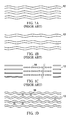
- the frequency-modulated signals are recorded in main track 12 ( FIG. 1A ) by way of track wobble, so it is usually referred as an absolute time-code in pre-groove (ATIP), in which the wobbled main track 12 is the area for a user to record information.
- this track modulation format is also used in, for example, CD-RW or MD (mini disc).
- the two kinds of data signals are modulated by a carrier phase modulation ( FIG. 1 B) .
- the format in the second category is used in such as the early MO disk, in which the parameter data is recorded in an inner annular area by a way similar to bar-coding, while the address information is recorded in a header area 15 ( FIG. 1 C) by cutting the track at some locations to form pits.
- the recording format of a DVD-R disc is that the recording process is performed using so called land pre-pits (LPP) method as shown in FIG. 1 D (referring to U.S. Patent 6,075,761 ).
- LPP land pre-pits
- intermittent and short small pits 16 are embossed in land area between two adjacent main tracks 12 corresponding to specific phase position for recording track wobble.
- the pits data need to be read and decoded with reference to the phases of track wobble signals.
- the three pulses with particularly high-level represent the locations of small pits 16.
- the inner lead-in area has a control data zone, in which the parameter data and the address information data are recorded by way of LPP, while only address information data is recorded in the remaining area of DVD-R disc.
- the parameter data Before a manufactured DVD-R is released to the market, the parameter data has to be written into the control data zone by a conventional burning process using a pre-writer.
- the main track 12 itself is subjected to a track modulation which is a method for recording modulated control data by track wobble in redial direction.
- a track modulation which is a method for recording modulated control data by track wobble in redial direction.
- the format of frequency-modulated recording via track wobble used in such as CD-R and MD is problematic for the case of a high density optical recording carrier.
- the significantly reduced distance between adjacent tracks in the high density optical recording carrier may cause the signal-to-noise ratio (S/N) of the track wobble signal become lower, and the reading of a wobble signal is thus disturbed by crosstalk from an adjacent track signal.
- S/N signal-to-noise ratio
- the increased amplitude may lead to a slightly increased signal-to-noise ratio, the crosstalk from an adjacent track signal would be increased as well.
- phase modulation is employed in the DVD+R/RW format, so that the reading and decoding will be less disturbed by the crosstalk from an adjacent track signal even when a large track wobble is applied.
- the major disadvantage of this format is that the direction of a track may change instantly at the points corresponding to a phase conversion. Under such circumstance, when reading the recorded user data, a signal disturbance similar to that of an interrupted track will occur. Therefore, this track format is considered unfavorable since the recorded user data signals may be disturbed, and the error rate when reading data may increase.
- the recording spots are not maintained on a specific (central) location on the track during data recording.
- laser recording spots 14 deviate from the center of the tracks, so they may perform recording on the inner side of the track (center side of the optical recording carrier) or the outer side of the track (edge side of the optical recording carrier). Therefore, a higher jitter rate and a lower signal-to-noise ratio may be caused when the recorded data is read.
- the wobble frequency has to match the frequency band for recording the data to be recorded and control data, the usable frequency band is limited, and high frequencies cannot be chosen.
- the wobble frequency is used as a servo feedback signal for rotational speed control, so a low frequency may not satisfy the need for controlling a high density optical recording carrier with a high accuracy.
- the tracks thereof are divided into many sectors.
- a header area 15 is provided in front of each sector, and the control data is recorded in manner of intermittent pits.
- the recorded control data may be obtained by directly reading an electrical signal from a central aperture (CA) of an optical pickup head (detector).
- CA central aperture
- the track may be interrupted by the header areas 15, so this recording format is not suitable for continuously recording data such as CD music or DVD movies.
- a buffer gap is required for the optical recording carrier of this recording format to prevent the recorded data from overlapping the header signal in a recording area due to unstable control of rotational speed, and thus the recording density being reduced. Furthermore, the buffer gap should not be too small to absorb variations resulting from the aforesaid unstable control. Based upon the above reasons, this format is seldom used at present. Currently, the majority of recording carriers follow the method of using a continuous track to record data.
- the track for recording data needs to be provided with a considerable level of wobble.
- a relatively low level of wobble may be adopted, as the problems mentioned above, which are the crosstalk between adjacent track wobble signals and the increased jitter and error rate resulting from failing to maintain the recorded data at the center of the track due to track wobble, can only be eased but not completely precluded.
- the pit length of the LPP is equivalent to the length of the smallest recorded data pits, the recorded signal is prone to be disturbed by the LPP signal during reading, and thus causing misjudgement of the signal.
- the present invention provides an optical recording carrier and a method for manufacturing the same, of which the patterns and formats for a recording track and data to be recorded can be selected with high degree of freedom.
- the track pattern and the recording format can be adequately selected based on recording requirements, so an appropriate track recording mode can be provided to allow an optical pickup head to obtain a high quality signal when reading the recorded data.
- the present invention provides an optical recording carrier and a method for manufacturing the same, wherein control data is recorded in a simple and independent format.
- control data is recorded in a simple and independent format.
- the recorded control data can be directly read and independently decoded without using any additional reference signal, thereby extracting parameter data and address information from the control data to control the recording process.
- another object of the present invention is to provide a method for manufacturing an optical recording carrier which complies with the existing specification of an optical recording carrier, and is compatible with an existing reading device. Therefore, neither a redesigned circuit of the reading device nor a newly-developed reading device will be needed, and the aforesaid problems in association with the current specifications can be improved.
- yet another object of the present invention is to provide an optical recording carrier and a method for manufacturing the same.
- the optical recording carrier possesses compatibility between the specifications of high speed and high density optical recording carriers, thereby conforming to the development trend of high speed and high density optical recording carriers.
- the present invention provides an optical recording carrier comprising: a spiral track provided in a data recording area, wherein the spiral track includes a main track and a subtrack, the main track being a continuous groove used to record user data to be stored, the subtrack being configured to record control data including parameter data and address information data to control a recording process, and the control data recorded in the subtrack includes a clock signal, so the control data can be independently decoded without using any signal provided by the main track, the full width at half maximum (FWHM) and depth of the subtrack are narrower and shallower than those of the main track, the distance between the main track and the subtrack is equal to or less than half of that between two adjacent main tracks. In other words, the subtrack is closer to one of the two adjacent main tracks.
- the address information may be obtained via the adjacent subtrack.
- the FWHM and the depth of the subtrack are preferably equal to or less than half of those of the main track.
- the ratio of the volume of the subtrack to the volume of the main track is preferably less than 1/4.
- the distance between the main track and the subtrack is preferably equal to or more than 1/3 of the distance between the two adjacent main tracks.
- the subtrack is a continuous groove of which the width has been modulated, or is formed by arranging a plurality of intermittent pits of which the lengths, widths, or intervals have been modulated.
- the said modulation is a bi-phase modulation or a bi-phase code modulation.
- the modulation is preferably a frequency modulation (FM), pulse-width modulation (PWM), or pulse-position modulation (PPM).
- the present invention provides a method for manufacturing a recordable optical recording carrier compatible with CD-R, comprising the steps of: providing a spiral track including a main track and a subtrack in a data recording area, wherein the main track is a continuous groove used to record primary data to be stored, and the absolute time code data of CD-R is recorded in the subtrack to control a recording process.
- the subtrack has a FWHM and a depth that are narrower and shallower than those of the main track, and the distance between the main track and the subtrack is less than half of that between two adjacent main tracks.
- no wobble is applied on the main track.
- the FWHM and the depth of the subtrack are preferably equal to or less than half of those of the main track.
- a ratio of the volume of the subtrack to the volume of the main track is preferably less than 1/4.
- the distance between the main track and the subtrack is preferably equal to or more than 1/3 of the distance between the two adjacent main tracks.
- the subtrack is preferably to be a continuous groove whose width has been modulated, wherein a change of the width is equivalent to an absolute time code signal of CD-R.
- the subtrack is formed by arranging a plurality of intermittent pits of which the lengths, widths, or intervals have been modulated, wherein a variation of the lengths, widths, or intervals of the pits is equivalent to a frequency modulation of an absolute time code data of CD-R.
- the present invention since the user data will be recorded in the main track and the control data is pre-recorded in the subtrack, that is, the user data and the control data are recorded separately, the present invention provides a high degree of freedom in selecting track patterns for recording data and formats of data to be recorded. An adequate track pattern and a recording format may be selected based on the recording demand, so as to provide an appropriate track recording mode for enabling an optical pickup head to obtain a high quality signal when reading the recorded data.
- the recording formats for the main track and subtrack can be selected independently. Accordingly, the control data recorded in the subtrack can be directly read and independently decoded without using any additional reference signal provided by the main track. Therefore, the present invention is unlike a conventional DVD-R disk where control data has to be read and decoded with reference to the phase of a track wobble signal.
- the user data and the control data are recorded separately in the present invention, simple formats such as formats without track wobble can be used in the main track and subtrack, so that the user data and the control data can be recorded, read, and decoded in a simpler manner.
- the track used to record the user data in order to record both user data and control data in one track, the track used to record the user data has to record the control data by way of track wobble. Therefore, for being able to be recorded, the user data and the control data must comply with specific and complicated recording rules and formats. Moreover, the accuracy of data reading may be affected by the track wobble. In addition, the data has to be decoded through complicated decoding rules after being read.
- the adjacent tracks of the high density optical recording carrier are so close that the crosstalk from adjacent track signals would occur when an optical pickup head is reading a wobble signal, which results in a reduction of the signal-to-noise ratio (S/N) of the signal.
- S/N signal-to-noise ratio
- recording spots can be kept on the central position of a track during data recording.
- the deviation of the recording spots from the track center is small, so it does not tend to occur that the recording spot is on the inner side of the track in some cases while being on the outer side of the track in other cases. Accordingly, the signal-to-noise ratio may be increased and the jitter may be decreased when reading the recorded data.
- the frequency of the control data recorded in the subtrack may be elevated. Accordingly, the following situation occurring in a conventional CD-R optical recording carrier may be avoided: the track wobble frequency used in the servo feedback signal for controlling the rotational speed must avoid the frequency band of the user data and the control data to be recorded, which makes an elevated frequency inapplicable, and the need for controlling a high density optical recording carrier with a high accuracy cannot be fulfilled.
- the elevated frequency used in the present invention may become higher than the frequency response range for tracking the servo system, so the positional relationship between the optical pickup head and the main track may not be affected during the recording. As a result, the optical pickup head will move along the centerline of the main track, and the recording spot is kept at the central position of the main track.
- the FWHM and the depth of the subtrack are equal to or less than half of those of the main track, the user data recorded in the main track and the control data recorded in the subtrack can be clearly indentified when being read.
- the LPP signal and the smallest recorded signal will hardly be misjudged as being read due to the similar lengths thereof.
- the signal level of the control data recorded in the subtrack is far lower than that of the user data recorded in the main track. Therefore, the signal of the user data recorded in the main track will not be disturbed or adversely affected by the signal of the control data recorded in the subtrack during data reading.
- the optical recording carrier and the method for manufacturing the same according to the present invention may comply with the specification of a current optical recording carrier, and be compatible with a current reading device. Therefore, there is no need to redesign the circuit of a reading device or develop a new reading device, and the present invention possesses compatibility between the specifications of high speed and high density optical recording carriers. As a result, the present invention conforms to the development trend of high speed and high density optical recording carriers.
- FIG. 2A is a schematic diagram illustrating the top view of a track structure of an optical recording carrier according to the present invention
- FIG. 2B is a cross-section diagram of FIG. 2A taken along line A-A'.
- a photosensitive material is coated on an optical recording carrier substrate 11, so that data may be optically recorded, and the recorded data may also be optically read afterwards.
- a spiral track is provided on the optical recording carrier substrate 11, wherein the track is formed into two spiral lines, which are a main track 12 and a subtrack 13 respectively.
- the main track 12 is used to record user data to be stored, while the subtrack 13 is used to record control data containing parameter data and address information data.
- the main track 12 is a spirally continuous groove having a U-shaped cross-section in the radial direction of the optical recording carrier substrate 11, a depth (or height) deeper than that of the subtrack 13, and a FWHM broader than that of the subtrack 13.
- the subtrack 13 is a spiral groove having a depth equal to or less than half of that of the main track 12, and a FWHM equal to or less than half of that of the main track 12 (see FIG. 2B ).
- the control data recorded in the subtrack 13 may be read out independently, or read out and decoded by a track push-pull signal provided by the main track 12, so as to control the recording.
- the positional relationship between the main track 12 and the subtrack 13 of the optical recording carrier substrate 11 is described as follows: the center of the subtrack 13 is not located at the central position between two adjacent main tracks 12. Actually, the subtrack 13 is closer to one of these two main tracks 12. When recording or reading, the laser spot will focus on the main track 12, and the signal from the subtrack 13 close to the main track 12 will be read out at the same time.
- the main track 12 is used to record the user data to be stored. There may be either no periodical wobble or only a tiny wobble in the track.
- the subtrack 13 is used to record the control data which is needed for the optical recording carrier to record the user data.
- the control data includes recording power, disc capacity, reference scanning velocity, address information and so on. Since the user data and the control data are recorded in the main track 12 and the subtrack 13 separately, an adequate and independent format may be selected for recording the control data in the subtrack 13, thereby providing a high degree of freedom in format selection.
- a photosensitive material (a photoresist layer) is coated on a surface of a flat glass substrate, and then the photoresist layer on the glass substrate is exposed along a spiral track by moving two laser beams, which can both focus on the glass substrate, relative to the rotating glass substrate from a position near the center of the glass substrate towards the periphery thereof, or from a position on the periphery of the glass substrate towards the center thereof, in a well-controlled fashion.
- the distance between the two focal spots of the laser beams is less than half of the distance between two adjacent main tracks 12, so as to enable the formed subtrack 13 to be closer to one of the two main tracks 12.
- the laser beam used to form the main track 12 is controlled to perform the exposing process with a higher output power, while the laser beam used to form the subtrack 13 has a lower output power.
- a developing process is performed after the exposing process.
- the degree of development may be controlled, so as to develop the main track 12 to the glass surface to form a deeper and broader continuous groove having a U-shaped cross-section in the radial direction of the glass substrate, while partially developing the subtrack 13 to form a narrower and shallower pattern.
- the developed glass substrate is subsequently subjected to conventional manufacturing processes of an optical recording carrier, such as mold electroforming, separating, hole-punching, and plastic injection, to produce the optical recording carrier substrate 11.
- a wobble signal of a constant frequency may be applied on the laser beam used to form the main track 12, so as to enable the main track 12 to have a tiny wobble, which is used as a servo feedback signal for controlling the rotation in the subsequent recording step.
- this kind of wobble signals in the main track 12 because such signals may be provided by the subtrack 13 independently, and the main track 12 only needs to provide a groove pattern having a stable geometric shape, so as to enable the user data to be stably recorded thereon.
- the main track 12 and the subtrack 13 of the optical recording carrier substrate 11 are independent of each other, the main track 12 and the subtrack 13 may adopt different frequencies.
- a rotating servo signal of the subtrack 13 may be an integral multiple of the wobble frequency of the main track 12. Therefore, when the recording is performed on an optical recording carrier made of the optical recording carrier substrate 11 at different scanning velocities, a disk driver may select to lock either a signal from the main track 12 or a signal from the subtrack 13 based on a suitable control frequency, so that a specific frequency band is limited to perform the rotating servo control, thereby achieving a higher stability.
- the aforesaid data recorded in the subtrack may be used for modulating a carrier of a higher frequency by frequency modulation (FM) or other modulation methods, such as frequency-shift keying (FSK) and phase-shift keying (PSK).
- FM frequency modulation
- FSK frequency-shift keying
- PSK phase-shift keying
- the subtrack 13 is a continuous groove, it may also be a track formed by arranging a plurality of intermittent pits which have been subjected to the aforesaid modulations.
- the modulation method for the subtrack is described as follows.
- FIG. 3A is a schematic diagram illustrating a bi-phase modulation (or bi-phase mark code modulation) applied on the subtrack of an optical recording carrier according to the present invention
- FIG. 3B is a schematic diagram illustrating a frequency modulation applied on the subtrack of an optical recording carrier according to the present invention.
- the laser beam used to form the subtrack 13 records the control signal in the subtrack 13 by switching on/off the laser beam or modulating the laser output power with an acoustic optical modulator.
- the data recorded in the subtrack 13 may adopt any recording format other than that used in the main track 12, and may be directly read and independently decoded via a push-pull signal or central aperture signal of the optical pickup head. Since the subtrack 13 is not used to record user data and is shallow and narrow, when a disk driver performs a recording, a very low signal level is sufficient for a clear readout.
- the level of the signal is much lower than that of the recorded user data signal, so the reading of the recorded user data will not be affected adversely, thereby providing a high degree of freedom in selecting a data recording format for the subtrack 13.
- the signals may be adequately encoded in advance, for example, applying a bi-phase modulation or a bi-phase code modulation on them. Afterward, the signals may be directly recorded in the subtrack 13 in an optical mark format representing signal changes (see FIG. 3A ).
- the decoding may be performed independently.
- the data signals may be further modulated via other modulation methods, and then recorded in the subtrack 13, for example, they may be modulated via FM, PWM, FSK, or QPSK, and then recorded in the subtrack (see FIG. 3B ).
- the frequency band used to record the data signal is not within the control frequency band of the tracking servo mechanism (usually equal to or less than 10 KHz) and the frequency band used to record the user data (usually equal to or more than hundreds KHz), any possible interference can be avoided.
- the control frequency band of the tracking servo mechanism, and the frequency band of the user data in the main track 12 are not the same order, the interference caused by the proximity of the three frequency bands can be avoided, and a significantly large differentiation for the three frequency bands needed in conventional methods is no longer necessary.
- the distance between the main track 12 and the subtrack 13 should be small. Specifically, a distance between the main track 12 and the subtrack 13 is preferably less than half of the distance between two adjacent main tracks.
- the determination of the distance is a set of complicated parameter adjusting processes, as that is needed in establishing a production process for any kind of optical recording carriers. The main purpose of this adjustment is to enable the signal level of the control data read out by the optical pickup head to be within a predetermined specification range during the recording. In addition, the signal specifications of the recorded data must be met.
- Such adjustment may be achieved by coordinately adjusting two parameters, one of which is the distance between the main track 12 and the subtrack 13, and the other is the volume ratio of the main track 12 to the subtrack 13.
- the distance between the main track 12 and the subtrack 13 is set by the laser beam recorder, and this setting may be tuned by adjusting optical lenses or according to the deflector control signal of the subtrack 13.
- the volume ratio of the main track 12 to the subtrack 13 is a function of the laser power ratio and the developing parameters in the mastering process, so the volume ratio may be controlled by adjusting the laser power ratio of the main track 12 to the subtrack 13 in compliance with the developing parameters.
- the subtrack 13 is located between two adjacent main tracks 12 except for the outmost portion of the subtrack 13, and is closer to one of the two main tracks 12.
- d represents the distance between the two adjacent main tracks 12
- d' is the distance between the subtrack 13 and the main track 12, which is closer to the subtrack 13 among the two adjacent main tracks 12
- the optimized condition for achieving a best effect is " 1/3 d ⁇ d' ⁇ 1/2 d ".
- the volume ratio of the subtrack 13 to the main track 12 is equal to or less than 1/4.
- the volume ratio should be as small as possible, so that the effect caused by the deviation of the tracking spot from the track can be reduced, and the interference occurring in reading the recorded data can also be reduced.
- the main track 12 is preferably provided with a U-shaped cross-section in the radial direction
- the subtrack 13 is preferably provided with a V-shaped cross-section in the radial direction.
- such optical recording carriers made of the substrate 11 may lock the scanning speed via the clock signal provided by the control data recorded in the subtrack 13, and may use the push-pull signal or the central aperture signal of the optical pick up head to extract the control data embedded in the subtrack 13.
- the control data signal may be channel-encoded, modulated via carriers, and then recorded in the subtrack 13. Since the subtrack 13 is not a track used to record the user data, it is feasible to choose either channel encoding or carrier modulation, and thus providing a high degree of freedom in format selection. Accordingly, numerous problems concerning interferences and frequency band distributions, which should be considered for conventional optical recording carriers, can be disregarded in the present invention.
- Example 1 High density optical recording carrier
- the present invention may be used to develop a high density optical recording carrier, and one feasible method therefor is described as follows.
- a glass substrate 31 coated with photoresist is exposed to two laser beams.
- the one used to form the main track 12 has a higher power and a wobble signal is not necessary, while the other one used to form the subtrack 13 has a lower power.
- the power ratio of the latter laser beam to the former one must be determined based on the depth of the track to be formed after being developed.
- the best mode is that the main track 12 is formed to have a deeper and broader U-shaped groove, and the subtrack 13 is formed to have a V-shaped groove whose FWHM and depth are all equal to or less than half of those of the main track 12, wherein the two tracks are arranged in a double-spiral manner.
- the laser beam used to form the subtrack 13 directly records the control signal in the subtrack 13 via the acoustic optical modulator.
- the frequency band of the control signal is lower than that of the final signal to be recorded in the optical recording carrier.
- the frequency of the control signal of the subtrack 13 is only 100 KHz. Since the decupled frequency of 100 KHz is merely 1 MHz, it is impossible for such frequency band to overlap with that of the data to be recorded, and mutual interference will not occur.
- the control signal to be recorded may firstly be channel-encoded via a bi-phase modulation or a bi-phase mark modulation, and then recorded in the subtrack 13.
- the glass substrate is subsequently subjected to conventional manufacturing processes of an optical recording carrier, such as stamper electroforming, separating, hole-punching, and plastic injection, to produce the optical recording carrier substrate 11.
- an optical recording carrier After an optical recording carrier is made with the optical recording carrier substrate 11 having the main track 12 with a deeper U-shaped groove and the subtrack 13 with a shallower V-shaped groove, it is inserted into a recorder for recording.
- the tracking signal is extracted from the push-pull signal of the optical pickup head via a low pass filter, so as to control the tracking servo system; and the control signal is filtered out from the push-pull signal via a high-pass or band-pass filter to control the rotational servo system, and then the control signal is transferred to a decoding unit to undergo a decoding process, by which the recording process can be controlled.
- Example 2 optical recording carrier compatible with CD-R
- FIG. 4 is a schematic diagram illustrating a frequency modulation method for a conventional CD-R optical recording carrier.
- FIG. 5 shows a waveform of a wobble signal for a conventional CD-R optical recording carrier.
- a CD-R optical recording carrier adopts the frequency modulation method to modulate a control data (absolute time-code in pre-groove data, ATIP data) in a track wobble, and its track pattern and the read control signal are shown in FIG. 4 .
- the control data is firstly channel-modulated (via a bi-phase mark modulation) to produce a binary-coded data stream 22.
- a 22050 Hz frequency is used as a carrier 23 for frequency-modulating, via a FM modulator 24, the binary-coded data stream 22 which has undergone the channel encoding, so as to produce a modulated wobble signal 25.
- the wobble signal 25 is used to drive an optical device to produce a wobble track 26.
- the track of the CD-R optical recording carrier expresses a periodical wobble, of which the frequency is 22050 Hz at the nominal scanning velocity.
- the deviation of the modulation set by the FM modulator 24 is 1 KHz, so the 21050 Hz frequency represents a low level of the binary code, while 23050 Hz represents a high level.
- the average reading frequency thereof is remained at 22050 Hz.
- this 22050 Hz central frequency may be locked based on the frequency changes of the track modulation, so that the scanning velocity can be adjusted to a proper value.
- For a tracking signal obtained by the optical pickup head its frequencies around 22050 Hz need to be filtered via a band-pass filter to produce a proper push-pull signal, i.e. the wobble signal 25.
- a waveform of the wobble signal 25 expressed by an oscilloscope is shown in FIG. 5 .
- the wobble signal 25 is further frequency-demodulated into a binary channel code, and finally decoded to produce the control code.
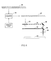
- FIG. 6 is a schematic diagram illustrating the production of a CD-R compatible optical recording carrier using the manufacturing method according to the present invention
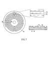
- FIG. 7 is a schematic diagram illustrating the structure of a CD-R compatible optical recording carrier according to the present invention.
- an equivalent CD-R tracking signal can be established, thereby equivalently enabling the tracking system of a disk driver to obtain the wobble signals.
- the method is described as follows. The frequency-modulated sinusoidal wave signal that is to be recorded in a CD-R track, i.e.
- the wobble signal 25 is converted to a square wave signal 27 by a comparator 32, and the duty cycle of the square wave signal 27 can be freely adjusted by changing the reference level signal, which is usually set at 50%.
- the square wave signal 27 is input to a laser power control device used for forming the subtrack 13, such as the acoustic optical modulator 33.
- the laser power control device can be used to control the laser power by turning on and off a laser beam 34 when forming the subtrack 13 so the exposure can be performed to the rotating glass substrate 31 coated with photoresist. Meanwhile, the main track 12 adopts a fixed-power laser beam 35 of which the power is much more than that of the subtrack 13 and in which no wobble control is included.
- the two laser beams focus on a surface of the glass substrate 31 via a lens set 36, advance along predetermined spiral tracks, and then expose the photoresist layer coated on the surface.
- the distances of the two track exposing spots relative to the rotation center are adjusted to be within a range of 1/3 to 1/2 of the distance between two adjacent main tracks.
- the exposed portions are washed away in a subsequent developing step, and two spiral tracks, which are the main track 12 and the subtrack 13, are formed as shown in FIG. 7 .
- the main track 12 is a continuous U-shaped groove, while the subtrack 13 includes intermittent V-shaped pits.
- the FWHM and depth of the V-shaped pits of the subtrack 13 are narrower and shallower than those of the U-shaped groove of the main track 12.
- the subtrack 13 is closer to one of the two adjacent main tracks 12, wherein the distance between the subtrack 13 and the main track 12, which is the one closer to the subtrack 13 among the two adjacent main tracks 12, is within a range of 1/3 to 1/2 of the distance between two adjacent main tracks 12.
- the exposed and developed glass substrate is subsequently subjected to conventional CD-R manufacturing processes to produce a CD-R.
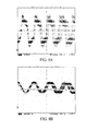
- FIG. 8A shows the waveform of an original push-pull signal without being band-pass filtered
- the waveform of a push-pull signal being band-pass filtered which is similar to the waveform of the general CD-R wobble signal shown in FIG. 5 .
- the control signal may be read out from this signal by conventional CD-R reading and decoding methods, so as to further control the burning process.
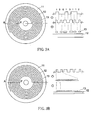
- the format of the optical recording carrier of the present invention is fully compatible with the conventional CD-R format. Since there is track wobble in the conventional CD-R disc, the optical pickup head does not always travel along the centerline of the wobbled track during the tracking. Therefore, when recording data, laser recording spots 14 used to record data may frequently deviate from the track, thus the pits burned by the laser recording spots 14 also deviate from the track and are not always accurately located on the track (as shown in FIG.
- the main track 12 used to record the data is not formed in a wobbled pattern as the conventional CD-R, so the laser recording spots 14 used to record data constantly remain on the centerline of the track during the data recording process.
- the pits burned by the laser recording spots 14 will less likely to deviate from the track and accurately located on center positions of the track (as shown in FIG. 11B ). Therefore, reading error is not prone to occur during the data reading process, and the jitter for the track can be lower (better).
- the above CD-R compatible optical recording carrier is not the only embodiment of the present invention.
- the laser beam's intensity of the subtrack 13 may also be modulated.
- FiGs. 9A-9C it has been proved that various aspects of subtrack 13 can be formed on the CD-R compatible optical recording carrier.
- FIG. 9A shows the case that uses intermittent pits, which are getting deeper and broader and then getting narrower and shallower, to record data of the subtrack 13, and a wobble signal waveform more similar to the sinusoidal wave may be obtained via such format of optical recording carrier.
- FIG. 9B shows the case that achieves the same object by means of the width changes of the subtrack 13.
- FIG. 9A shows the case that uses intermittent pits, which are getting deeper and broader and then getting narrower and shallower, to record data of the subtrack 13, and a wobble signal waveform more similar to the sinusoidal wave may be obtained via such format of optical recording carrier.
- FIG. 9B shows the case that achieves the same object by means of the width changes of the subtrack 13.
- FIG. 9C shows the case that uses the length changes of the pits to enable the optical reading signal to obtain a wobble signal similar to that of CD-R.
- the exemplary track patterns of the present invention are described for illustrating a high degree of freedom in selecting the track pattern of the subtrack 13 for recording the control signal.
- all track patterns mentioned above are compatible with CD-R.
Landscapes
- Engineering & Computer Science (AREA)
- Manufacturing & Machinery (AREA)
- Optical Recording Or Reproduction (AREA)
Applications Claiming Priority (1)
| Application Number | Priority Date | Filing Date | Title |
|---|---|---|---|
| TW100114479A TW201243842A (en) | 2011-04-26 | 2011-04-26 | Recordable compact disk and method of manufacturing recordable compact disk compatible with CD-R |
Publications (1)
| Publication Number | Publication Date |
|---|---|
| EP2518726A1 true EP2518726A1 (fr) | 2012-10-31 |
Family
ID=45094461
Family Applications (1)
| Application Number | Title | Priority Date | Filing Date |
|---|---|---|---|
| EP11189415A Withdrawn EP2518726A1 (fr) | 2011-04-26 | 2011-11-16 | Support d'enregistrement optique enregistrable et procédé pour la fabrication d'un enregistrement optique enregistrable compatible avec un CD-R |
Country Status (4)
| Country | Link |
|---|---|
| US (1) | US20120275283A1 (fr) |
| EP (1) | EP2518726A1 (fr) |
| CN (1) | CN102760457A (fr) |
| TW (1) | TW201243842A (fr) |
Citations (4)
| Publication number | Priority date | Publication date | Assignee | Title |
|---|---|---|---|---|
| EP0397238A1 (fr) * | 1989-05-08 | 1990-11-14 | Koninklijke Philips Electronics N.V. | Système d'enregistrement d'information, dispositif d'enregistrement et support d'enregistrement destinés à être utilisés dans un tel système d'enregistrement d'information |
| US6075761A (en) | 1996-04-02 | 2000-06-13 | Sony Corporation | Optical recording medium having pits that are formed with respect to a wobbled groove at substantially constant positions in each cycle of the groove having a pit |
| EP1154414A2 (fr) * | 2000-05-10 | 2001-11-14 | Sony Corporation | Support d'enregistrement optique, disque maítre pour la fabrication du support d'enregistrement optique, et appareil optique d'enregistrement et/ou de reproduction |
| US20110032810A1 (en) * | 2007-06-06 | 2011-02-10 | Gunter Beulich | Master device |
Family Cites Families (5)
| Publication number | Priority date | Publication date | Assignee | Title |
|---|---|---|---|---|
| US6310838B1 (en) * | 1997-09-03 | 2001-10-30 | U.S. Philips Corporation | Record carrier and apparatus for scanning the record carrier |
| JP2002074664A (ja) * | 2000-08-31 | 2002-03-15 | Sony Corp | 記録装置および方法、再生装置および方法、並びに記録媒体 |
| EP1486956A1 (fr) * | 2002-03-15 | 2004-12-15 | Kabushiki Kaisha Toshiba | Support d'enregistrement d'informations, et dispositif et procede d'enregistrement/de reproduction |
| JP2005317141A (ja) * | 2004-04-30 | 2005-11-10 | Nec Corp | 光ディスク媒体および光ディスク装置 |
| WO2007010825A2 (fr) * | 2005-07-15 | 2007-01-25 | Pioneer Corp | Support d’enregistrement de données, dispositif et procédé de lecture de données, et dispositif et procédé de fabrication de support d’enregistrement de données |
-
2011
- 2011-04-26 TW TW100114479A patent/TW201243842A/zh unknown
- 2011-11-16 EP EP11189415A patent/EP2518726A1/fr not_active Withdrawn
- 2011-11-16 US US13/298,088 patent/US20120275283A1/en not_active Abandoned
- 2011-12-14 CN CN2011104180724A patent/CN102760457A/zh active Pending
Patent Citations (4)
| Publication number | Priority date | Publication date | Assignee | Title |
|---|---|---|---|---|
| EP0397238A1 (fr) * | 1989-05-08 | 1990-11-14 | Koninklijke Philips Electronics N.V. | Système d'enregistrement d'information, dispositif d'enregistrement et support d'enregistrement destinés à être utilisés dans un tel système d'enregistrement d'information |
| US6075761A (en) | 1996-04-02 | 2000-06-13 | Sony Corporation | Optical recording medium having pits that are formed with respect to a wobbled groove at substantially constant positions in each cycle of the groove having a pit |
| EP1154414A2 (fr) * | 2000-05-10 | 2001-11-14 | Sony Corporation | Support d'enregistrement optique, disque maítre pour la fabrication du support d'enregistrement optique, et appareil optique d'enregistrement et/ou de reproduction |
| US20110032810A1 (en) * | 2007-06-06 | 2011-02-10 | Gunter Beulich | Master device |
Also Published As
| Publication number | Publication date |
|---|---|
| US20120275283A1 (en) | 2012-11-01 |
| CN102760457A (zh) | 2012-10-31 |
| TW201243842A (en) | 2012-11-01 |
Similar Documents
| Publication | Publication Date | Title |
|---|---|---|
| US8254226B2 (en) | Disc-shaped recording medium, cutting apparatus for same, and disc drive | |
| US8553511B2 (en) | Disk recording medium, disk production method, disk drive apparatus | |
| US9449642B2 (en) | Record carrier and apparatus for scanning the record carrier | |
| KR100896866B1 (ko) | 디스크형 기록 매체, 디스크 드라이브 장치 및 디스크형 기록 매체의 제조 장치 및 방법 | |
| CN1314016C (zh) | 信息记录方法及设备、记录媒体制造设备和方法 | |
| US20020021658A1 (en) | Rewritable optical recording medium and manufacturing method and apparatus therefor | |
| EP2518726A1 (fr) | Support d'enregistrement optique enregistrable et procédé pour la fabrication d'un enregistrement optique enregistrable compatible avec un CD-R | |
| EP1609137B1 (fr) | Disque optique multicouches a modulation de pre-spirale | |
| CN1331118C (zh) | 估算信息记录介质的摆动信号的方法 | |
| RU2295164C2 (ru) | Дисковый носитель записи, устройство для нарезки и привод диска | |
| HK1064206B (en) | Record carrier and apparatus for scanning the record carrier |
Legal Events
| Date | Code | Title | Description |
|---|---|---|---|
| PUAI | Public reference made under article 153(3) epc to a published international application that has entered the european phase |
Free format text: ORIGINAL CODE: 0009012 |
|
| AK | Designated contracting states |
Kind code of ref document: A1 Designated state(s): AL AT BE BG CH CY CZ DE DK EE ES FI FR GB GR HR HU IE IS IT LI LT LU LV MC MK MT NL NO PL PT RO RS SE SI SK SM TR |
|
| AX | Request for extension of the european patent |
Extension state: BA ME |
|
| STAA | Information on the status of an ep patent application or granted ep patent |
Free format text: STATUS: THE APPLICATION IS DEEMED TO BE WITHDRAWN |
|
| 18D | Application deemed to be withdrawn |
Effective date: 20130503 |