EP2518754A2 - Lampe électrique dotée d'un piston extérieur et d'une lampe intégrée et procédé de fabrication associé - Google Patents
Lampe électrique dotée d'un piston extérieur et d'une lampe intégrée et procédé de fabrication associé Download PDFInfo
- Publication number
- EP2518754A2 EP2518754A2 EP12164505A EP12164505A EP2518754A2 EP 2518754 A2 EP2518754 A2 EP 2518754A2 EP 12164505 A EP12164505 A EP 12164505A EP 12164505 A EP12164505 A EP 12164505A EP 2518754 A2 EP2518754 A2 EP 2518754A2
- Authority
- EP
- European Patent Office
- Prior art keywords
- lamp
- base
- power supply
- base body
- clip
- Prior art date
- Legal status (The legal status is an assumption and is not a legal conclusion. Google has not performed a legal analysis and makes no representation as to the accuracy of the status listed.)
- Withdrawn
Links
Images








Classifications
-
- H—ELECTRICITY
- H01—ELECTRIC ELEMENTS
- H01J—ELECTRIC DISCHARGE TUBES OR DISCHARGE LAMPS
- H01J5/00—Details relating to vessels or to leading-in conductors common to two or more basic types of discharge tubes or lamps
- H01J5/50—Means forming part of the tube or lamps for the purpose of providing electrical connection to it
- H01J5/54—Means forming part of the tube or lamps for the purpose of providing electrical connection to it supported by a separate part, e.g. base
- H01J5/58—Means for fastening the separate part to the vessel, e.g. by cement
- H01J5/60—Means for fastening the separate part to the vessel, e.g. by cement for fastening by mechanical means
-
- H—ELECTRICITY
- H01—ELECTRIC ELEMENTS
- H01J—ELECTRIC DISCHARGE TUBES OR DISCHARGE LAMPS
- H01J5/00—Details relating to vessels or to leading-in conductors common to two or more basic types of discharge tubes or lamps
- H01J5/50—Means forming part of the tube or lamps for the purpose of providing electrical connection to it
- H01J5/54—Means forming part of the tube or lamps for the purpose of providing electrical connection to it supported by a separate part, e.g. base
- H01J5/62—Connection of wires protruding from the vessel to connectors carried by the separate part
-
- H—ELECTRICITY
- H01—ELECTRIC ELEMENTS
- H01K—ELECTRIC INCANDESCENT LAMPS
- H01K1/00—Details
- H01K1/42—Means forming part of the lamp for the purpose of providing electrical connection, or support for, the lamp
- H01K1/46—Means forming part of the lamp for the purpose of providing electrical connection, or support for, the lamp supported by a separate part, e.g. base, cap
- H01K1/48—Removable caps
Definitions
- the object of the present invention is, in a lamp according to the preamble of claim 1, the installation of a built-in lamp in an outer bulb by means of mounting clip safely and reliably, but nevertheless to accomplish in a simple manner.
- the invention ensures the simple and reliable production of a lamp with built-in lamp.
- the invention provides, in particular, a single-ended electric lamp with an outer bulb fastened to a base and an integral lamp which is arranged inside the outer bulb and which is robust and easy to produce.
- the lamp or integral lamp is a high-voltage halogen incandescent lamp, wherein at least two pins act as power supply wires.
- the lamp can also be a high-pressure discharge lamp.
- the built-in lamp has a piston with pinch, which is held by means of a retaining clip on the plate base.
- the lamp or integral lamp consists essentially of a hermetically sealed lamp vessel or bulb with pinch, of at least one light source and a power supply system for the lamp, which usually has two external power supply lines, which protrude axially parallel from the pinch.
- the light source is usually a luminous element, but it can also be a discharge arc between two electrodes. In the following, the light source will always be described as a luminous element for the sake of simplicity. He is often over internal power supply and possibly films connected to the external power supply lines.
- the power supply system connects the lamp arranged in the interior of the lamp vessel with a lamp arranged outside the base, which is to be connected to a power source.
- the power supply system consists, for example, of inner power supply wires, of fuser films and of outer power supply wires, wherein the aligned ends of the inner and outer power supply wires and the power supply wires interconnecting fusing films are fused in the lamp crimp.
- Relevant to the invention is only the pinch and the outwardly projecting wires of the external power supply lines.
- the piston is usually filled with an inert gas and a halogen additive.
- a high-pressure discharge lamp can be used in particular as a built-in lamp, similar to DE-A 32 32 207 described.
- the joke of the invention is that the power supply is connected to a holding clip, which takes over the further contact with the socket for this power supply.
- the novel concept is particularly suitable for increasing the luminous flux of the lamp.
- the problem is solved to increase the efficiency of such lamps in the simplest possible way.
- the retaining clip consists of two independent clip parts, which can be similar in principle, albeit mirrored. Below is the construction a Garclipteils, often called only clip part described in more detail.
- the clip part has a pair of spring tongues for fixing the pinch of the built-in lamp and a docking station for the supply line, which protrudes from a Tellerfuß up to the recessed lamp out, as well as at least one body, which ensures the connection between the supply line and associated external power supply of the recessed lamp and at the same time either encloses the pinch laterally or serves as a stop for the foundation of the pinch. From this foundation, the external power supply of the built-in lamp exit.
- the base body and docking station are at a different height level with respect to the longitudinal axis, whereby, together with the spring tongues, a considerable material saving is achieved EP2239762 is achieved.
- body and docking station are at the same height level, which is why about twice as much material is required for the retaining clip part.
- the retaining clip can now be better adapted to the pinch of the recessed lamp.
- the centering part has in its inner surface an opening which serves as a centering inlet for an external power supply of the built-in lamp. This opening can be completely within the edge of the centering, but it can also extend as a recess partially to the edge. All parts are advantageously flat surfaces which are connected to each other via bends.
- auxiliary plate is attached, which is arranged at approximately 90 ° laterally to this first side wall. It is preferably oriented parallel to the base wall.
- a U-shaped clamping part attached as a docking station with two side walls which are oriented so that they are parallel to the free end of a protruding from the base plate of the lamp supply line supplied from the base forth is, are aligned.
- the distance between the two side walls to each other is just chosen so that the supply line or its free end can be clamped therein, which possibly happens by subsequent adjustment of this distance, whereby a good clamping effect is ensured. Since this distance is relatively small, the base part is rather poor compared to the side walls. Often it is just a bent connector. To save material and for easier bending, the clamping part often has recessed windows in the area of the base part.
- the two spring tongues are mutually substantially parallel and axially parallel to the longitudinal axis of the lamp. They are clamped to the two broad sides of the bruise.
- the free ends of the spring tongues are preferably corrugated.
- the socket takes place by serving as a holder for the integral lamp two retaining clip parts, which include the pinch of the integral lamp.
- the retaining clip parts are docked to the leads, which protrude from the disc base, as stated above. Then they are fixed by laser welding. Thereafter, a usual socket is attached.
- a secure connection is preferably achieved by laser welding between the feed line and the clamping part, similar to what happens between outer power supply and extension part of the base wall of the clip part, in particular, even both welding operations occur simultaneously or immediately in succession.
- the efficiency of the lamp is increased by minimizing the luminous flux losses in the direction of the base.
- the frame structure is changed and adapted the manufacturing process of the socket.
- the reflector disc also preferably has a first recess, which is preferably rectangular, for the disc base.
- each external power supply of the integral lamp is bent laterally to the nearest narrow side of the pinch and returned to this, preferably slightly protruding.
- the integral lamp is mounted on the clip, or on two clip parts, and attached the free end of the bent outer power supply to the clip part by laser or Widerstresch resumeen, in principle, also satisfies the mechanical contact.
- a reflector plate is attached to the bottom of the clip part, so that the pins of the clip part engage in the slots of the reflector disc, the free ends of the pins are angled adjoin, so that a locking of the reflector disc is ensured.
- the minimized shadowing of the clip keeps the luminous flux loss of the built-in lamp as low as possible.
- the luminous flux losses are reduced by the use of the reflector part.
- the bent-free end of the outer power supply engages other latching springs of the clip part, so that can be dispensed with extra welding.
- the auxiliary plate may have a transverse to the longitudinal axis attached support member for the reflector disk.
- the reflector disc has substantially as an edge on a circular arc and a straight edge which connects the ends of the circular arc.
- the reflector disc is not a separate part, but is attached integrally to the retaining clip.
- FIG. 1 represents a complete halogen incandescent lamp 1.
- a base 2 of the commercial type E14 or E27 in particular with ceramic base or lamp support and attached screw 3 and base sleeve 4, an outer bulb 5 is held in the base sleeve 4 by means of putty.
- a built-in lamp 6 is arranged within the outer bulb 5.
- the integral lamp is designed as a so-called high-voltage halogen incandescent lamp and known as such from the prior art.
- the lamp 1 has a longitudinal axis A, on which the built-in lamp is aligned.
- the built-in lamp 6, see also FIG. 2 is equipped with a single pinch 7 having two broad sides 8a and 8b and two narrow sides 9a and 9b and a bottom part 10 equipped. From the pinch 7 project pin-like external power supply 11 out. According to FIG. 2 These outer power supply lines 11 are angled outwards in the direction of the narrow side of the pinch, the free ends are slightly obliquely outward. Slightly inclined means in particular at an angle of 5 to 30 ° inclined to the longitudinal axis A.
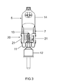
- a partial clip 21 connects an external power supply 11 via a main body and a docking station with a coming from the base forth supply line 13, which is melted in a cup base 12.
- FIGS. 4a and 4b shows in each case a section through the pinch seal 7 with retaining clip 20 and a detail of the docking station 33.
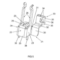
- FIG. 5 shows a partial clip 21 with a plate-like base body 22, which is divided into three U-shaped sub-plates.
- a first sub-plate is a side wall 23. It is parallel to the axis A and approximately in extension of second broad side 8b of the pinch 7 aligned and is located directly below the pinch 7.
- the first side wall 23 has an upper edge which shows a pinch, a lower edge which faces the socket, an inner edge which faces away from the axis A, and an outer edge which faces the axis A.
- two spring tongues 26 are arranged so that they face each other and thereby comprise the two broad sides 8a and 8b of the pinch.
- a centering 28 plate-like between the base of the two spring tongues 26 extends, however, angled at 90 °, a centering 28 plate-like between the base of the two spring tongues 26. It is essentially a rectangular plate having a substantially oval opening 29 in the middle, and the it is intended to center the free bent end of the outer power supply 11 and to contact, see above all FIG. 6a ,
- auxiliary plate 30 which branches off from the outer edge 31 of the side wall.
- extension part 32 is angled, which is oriented transversely to the longitudinal axis A, similar as well as the centering 28.
- the docking station 33 sits for coming from the base 2 ago supply line.
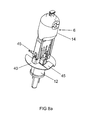
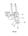
- the latch spring 46 presses with its free leg 49 against the outer power supply 11, whereby the mechanical contact is significantly improved.
- a laser welding for the connection is not essential here, but quite advantageous.
- An assembly process using the retaining clip is carried out in the following steps: First, the first and second clip part and the built-in lamp are provided with angled outer power supply lines.
- the base body is electrically connected to the base sleeve via a first supply line, thus the side contact is realized.
- the center contact is realized by soldering the extension wire in the ground contact of the socket, the eye.
Landscapes
- Fastening Of Light Sources Or Lamp Holders (AREA)
- Non-Portable Lighting Devices Or Systems Thereof (AREA)
- Multi-Conductor Connections (AREA)
- Connecting Device With Holders (AREA)
Applications Claiming Priority (1)
| Application Number | Priority Date | Filing Date | Title |
|---|---|---|---|
| DE202011005637U DE202011005637U1 (de) | 2011-04-27 | 2011-04-27 | Elektrische Lampe mit einem Außenkolben und einer Einbaulampe |
Publications (2)
| Publication Number | Publication Date |
|---|---|
| EP2518754A2 true EP2518754A2 (fr) | 2012-10-31 |
| EP2518754A3 EP2518754A3 (fr) | 2013-01-02 |
Family
ID=44974199
Family Applications (1)
| Application Number | Title | Priority Date | Filing Date |
|---|---|---|---|
| EP12164505A Withdrawn EP2518754A3 (fr) | 2011-04-27 | 2012-04-17 | Lampe électrique dotée d'un piston extérieur et d'une lampe intégrée et procédé de fabrication associé |
Country Status (4)
| Country | Link |
|---|---|
| US (1) | US20120274199A1 (fr) |
| EP (1) | EP2518754A3 (fr) |
| CN (1) | CN102760637A (fr) |
| DE (1) | DE202011005637U1 (fr) |
Cited By (1)
| Publication number | Priority date | Publication date | Assignee | Title |
|---|---|---|---|---|
| DE102013223904A1 (de) * | 2013-11-22 | 2015-05-28 | Osram Gmbh | Elektrische Lampe |
Families Citing this family (3)
| Publication number | Priority date | Publication date | Assignee | Title |
|---|---|---|---|---|
| IN2012DE02309A (fr) * | 2012-07-25 | 2015-10-16 | Flowil Int Lighting | |
| DE102012219135A1 (de) | 2012-10-19 | 2014-04-24 | Osram Gmbh | Reflektorlampe |
| CN115507335B (zh) * | 2022-11-21 | 2023-01-24 | 保定来福汽车照明集团有限公司 | 一种汽车卤素灯 |
Citations (2)
| Publication number | Priority date | Publication date | Assignee | Title |
|---|---|---|---|---|
| DE3232207A1 (de) | 1982-08-30 | 1984-03-08 | Patent-Treuhand-Gesellschaft für elektrische Glühlampen mbH, 8000 München | Hochdruckentladungslampe kleiner leistung |
| EP2239762A2 (fr) | 2009-04-08 | 2010-10-13 | Osram Gesellschaft mit beschränkter Haftung | Lampe électrique dotée d'un piston extérieur et d'une lampe intégrée |
Family Cites Families (13)
| Publication number | Priority date | Publication date | Assignee | Title |
|---|---|---|---|---|
| NL7018535A (fr) * | 1969-12-29 | 1971-07-01 | ||
| JPS5737913Y2 (fr) * | 1978-04-04 | 1982-08-20 | ||
| JPS6010436B2 (ja) * | 1979-12-20 | 1985-03-16 | 株式会社東芝 | 光源装置の製造方法 |
| US4264117A (en) * | 1979-12-21 | 1981-04-28 | Amp Incorporated | Socket for wedge base incandescent lamp |
| US4769574A (en) * | 1986-08-04 | 1988-09-06 | Koito Seisakusho Co., Ltd. | Incandescent lamp with a metal coupling to a plastic lamp base for automotive headlamp and like lighting applications |
| HU202677B (en) * | 1989-03-10 | 1991-03-28 | Tungsram Reszvenytarsasag | Incandescent lamp |
| US6884118B2 (en) * | 2003-06-13 | 2005-04-26 | Christiana Industries, Llc | Lead aligning terminal |
| DE102004049500A1 (de) * | 2004-10-11 | 2006-04-20 | Patent-Treuhand-Gesellschaft für elektrische Glühlampen mbH | Lampe mit Einbaulampe |
| DE102004060918A1 (de) * | 2004-12-17 | 2006-06-22 | Patent-Treuhand-Gesellschaft für elektrische Glühlampen mbH | PAR-Lampenanordnung |
| DE202006004952U1 (de) * | 2006-03-28 | 2006-06-08 | Patent-Treuhand-Gesellschaft für elektrische Glühlampen mbH | Elektrische Lampe mit Strahlungsschutzclip |
| DE102007035595A1 (de) * | 2007-07-30 | 2009-02-05 | Osram Gesellschaft mit beschränkter Haftung | Elektrische Lampe mit einem Außenkolben und einer Einbaulampe sowie ein Verfahren zu deren Herstellung |
| DE102008028383B4 (de) * | 2008-06-13 | 2019-12-24 | Ledvance Gmbh | Elektrische Lampe mit einem Außenkolben und einer Einbaulampe |
| DE202008016865U1 (de) * | 2008-12-19 | 2010-02-11 | Osram Gesellschaft mit beschränkter Haftung | Elektrische Lampe mit einem Außenkolben und einer Einbaulampe |
-
2011
- 2011-04-27 DE DE202011005637U patent/DE202011005637U1/de not_active Expired - Lifetime
-
2012
- 2012-04-17 EP EP12164505A patent/EP2518754A3/fr not_active Withdrawn
- 2012-04-27 US US13/457,528 patent/US20120274199A1/en not_active Abandoned
- 2012-04-27 CN CN2012101297764A patent/CN102760637A/zh active Pending
Patent Citations (2)
| Publication number | Priority date | Publication date | Assignee | Title |
|---|---|---|---|---|
| DE3232207A1 (de) | 1982-08-30 | 1984-03-08 | Patent-Treuhand-Gesellschaft für elektrische Glühlampen mbH, 8000 München | Hochdruckentladungslampe kleiner leistung |
| EP2239762A2 (fr) | 2009-04-08 | 2010-10-13 | Osram Gesellschaft mit beschränkter Haftung | Lampe électrique dotée d'un piston extérieur et d'une lampe intégrée |
Cited By (2)
| Publication number | Priority date | Publication date | Assignee | Title |
|---|---|---|---|---|
| DE102013223904A1 (de) * | 2013-11-22 | 2015-05-28 | Osram Gmbh | Elektrische Lampe |
| US9218952B2 (en) | 2013-11-22 | 2015-12-22 | Osram Gmbh | Electric lamp including a built-in-lamp having a pinch seal |
Also Published As
| Publication number | Publication date |
|---|---|
| DE202011005637U1 (de) | 2011-10-19 |
| EP2518754A3 (fr) | 2013-01-02 |
| CN102760637A (zh) | 2012-10-31 |
| US20120274199A1 (en) | 2012-11-01 |
Similar Documents
| Publication | Publication Date | Title |
|---|---|---|
| WO1998040936A1 (fr) | Lampe a halogene avec douille | |
| EP2518754A2 (fr) | Lampe électrique dotée d'un piston extérieur et d'une lampe intégrée et procédé de fabrication associé | |
| DE29910604U1 (de) | Reflektorlampe | |
| DE102012219135A1 (de) | Reflektorlampe | |
| EP2458614B1 (fr) | Lampe électrique comprenant une ampoule extérieure et une lampe intégrée | |
| EP2020678A2 (fr) | Lampe électrique dotée d'un piston extérieur et d'une lampe intégrée agencée dans le piston extérieur | |
| DE102008028383B4 (de) | Elektrische Lampe mit einem Außenkolben und einer Einbaulampe | |
| EP1714306B1 (fr) | Ampoule de phare de vehicule | |
| DE102010002769A1 (de) | Elektrische Lampe mit einem Außenkolben und einer Einbaulampe und zugehöriges Herstellverfahren | |
| WO2010069681A1 (fr) | Lampe électrique comportant un piston extérieur et une lampe intégrée | |
| DE202009005396U1 (de) | Elektrische Lampe mit einem Außenkolben und einer Einbaulampe | |
| EP1672276B1 (fr) | Lampe à réflecteur parabolique | |
| EP2399268A1 (fr) | Lampe électrique comportant un piston extérieur et une lampe intégrée | |
| DE202011005509U1 (de) | Elektrische Lampe mit einem Außenkolben und einer Einbaulampe und zugehöriges Herstellverfahren | |
| DE3126036A1 (de) | "elektrische lampenanordnung" | |
| DE102013223904A1 (de) | Elektrische Lampe | |
| DE2355637A1 (de) | Elektrische lampe und verfahren zu deren herstellung | |
| DE102010061964A1 (de) | Elektrische Lampe mit einem Außenkolben und einer Einbaulampe und zugehöriges Herstellverfahren | |
| DE102005003129A1 (de) | Hochdruckentladungslampe | |
| DE102007003491B4 (de) | Lampe | |
| EP2084727B1 (fr) | Source électrique de lumière destinée en particulier pour utilisation dans un réflecteur | |
| WO2009059882A2 (fr) | Lampe électrique dotée d'une ampoule extérieure et d'une lampe intégrée | |
| DE3000318A1 (de) | Elektrische strahlerlampe, insbesondere fuer den einsatz als fahrzeugscheinwerfer | |
| WO2008119623A1 (fr) | Module pour ampoule électrique comprenant un verre externe | |
| WO2006066534A2 (fr) | Procede de fixation et lampe ainsi produite |
Legal Events
| Date | Code | Title | Description |
|---|---|---|---|
| PUAI | Public reference made under article 153(3) epc to a published international application that has entered the european phase |
Free format text: ORIGINAL CODE: 0009012 |
|
| AK | Designated contracting states |
Kind code of ref document: A2 Designated state(s): AL AT BE BG CH CY CZ DE DK EE ES FI FR GB GR HR HU IE IS IT LI LT LU LV MC MK MT NL NO PL PT RO RS SE SI SK SM TR |
|
| AX | Request for extension of the european patent |
Extension state: BA ME |
|
| PUAL | Search report despatched |
Free format text: ORIGINAL CODE: 0009013 |
|
| AK | Designated contracting states |
Kind code of ref document: A3 Designated state(s): AL AT BE BG CH CY CZ DE DK EE ES FI FR GB GR HR HU IE IS IT LI LT LU LV MC MK MT NL NO PL PT RO RS SE SI SK SM TR |
|
| AX | Request for extension of the european patent |
Extension state: BA ME |
|
| RIC1 | Information provided on ipc code assigned before grant |
Ipc: H01K 1/48 20060101ALI20121123BHEP Ipc: H01J 5/60 20060101AFI20121123BHEP |
|
| RAP1 | Party data changed (applicant data changed or rights of an application transferred) |
Owner name: OSRAM GMBH |
|
| RAP1 | Party data changed (applicant data changed or rights of an application transferred) |
Owner name: OSRAM GMBH |
|
| STAA | Information on the status of an ep patent application or granted ep patent |
Free format text: STATUS: THE APPLICATION IS DEEMED TO BE WITHDRAWN |
|
| 18D | Application deemed to be withdrawn |
Effective date: 20130703 |