EP2518905A1 - Détermination de la fiabilité d'une liaison de fréquence radio - Google Patents
Détermination de la fiabilité d'une liaison de fréquence radio Download PDFInfo
- Publication number
- EP2518905A1 EP2518905A1 EP11290208A EP11290208A EP2518905A1 EP 2518905 A1 EP2518905 A1 EP 2518905A1 EP 11290208 A EP11290208 A EP 11290208A EP 11290208 A EP11290208 A EP 11290208A EP 2518905 A1 EP2518905 A1 EP 2518905A1
- Authority
- EP
- European Patent Office
- Prior art keywords
- radio frequency
- determining
- reliability
- field
- frequency link
- Prior art date
- Legal status (The legal status is an assumption and is not a legal conclusion. Google has not performed a legal analysis and makes no representation as to the accuracy of the status listed.)
- Withdrawn
Links
Images

Classifications
-
- H—ELECTRICITY
- H04—ELECTRIC COMMUNICATION TECHNIQUE
- H04B—TRANSMISSION
- H04B5/00—Near-field transmission systems, e.g. inductive or capacitive transmission systems
- H04B5/70—Near-field transmission systems, e.g. inductive or capacitive transmission systems specially adapted for specific purposes
- H04B5/77—Near-field transmission systems, e.g. inductive or capacitive transmission systems specially adapted for specific purposes for interrogation
Definitions
- the invention relates to method of determining a reliability of a radio frequency link between a near field communication device and a reader device.
- the invention relates to a radio frequency level detector.
- the invention relates to a near field communication device. Furthermore, the invention relates to a computer-readable medium.
- the invention relates to a program element.
- NFC near field communication
- a near field communication device for example a smart card
- a reader device for example a smart card
- a protocol is used, which is based on a wireless interface.
- the protocol establishes wireless network connections between the near field communication device on the one hand and the reader device on the other hand.
- there exists different operating distances typically in the range of 0 to 20 cm.
- the NFC protocol distinguishes between the initiator and the target of the communication.
- the initiator is the device that initiates and controls the exchange of data.
- the target is the device that answers the request from the initiator.
- the protocol specifies that the initiator is the device responsible to generate the radio frequency field. The quality of the communication depends highly on the quality of the communication link.
- a method of determining a reliability of a radio frequency link between a near field communication device and a reader device, a radio frequency level detector, a near field communication device, a computer-readable medium and a program element according to the independent claims are provided.
- a method of determining a reliability of a radio frequency link between a near field communication device and a reader device comprises providing, to a radio frequency level detector, an initial threshold value associated with an amplitude corresponding to a radio frequency field associated with the radio frequency link, detecting a radio frequency field, determining the amplitude corresponding to the detected radio frequency field, and determining a reliability of the radio frequency link based on the determined amplitude corresponding to the detected radio frequency field and the initial threshold value.
- a radio frequency level detector for determining a reliability of a radio frequency link between a near field communication device and a reader device.
- the radio frequency level detector comprises a receiving unit for receiving an initial threshold value associated with an amplitude corresponding to a radio frequency field associated with the radio frequency link being provided to the radio frequency level detector, a detection unit for detecting a radio frequency field, a determination unit for determining the amplitude corresponding to the detected radio frequency field and for determining a reliability of the radio frequency link based on the determined amplitude corresponding to the detected radio frequency field and the initial threshold value.
- a near field communication device comprises a radio frequency level detector having the above mentioned features.
- a computer-readable medium in which a computer program of determining a reliability of a radio frequency link between a near field communication device and a reader device is stored, which computer program, when being executed by a processor, is adapted to carry out or control a method having the above mentioned features.
- a program element for instance a software routine, in source code or in executable code
- determining a reliability of a radio frequency link between a near field communication device and a reader device is provided, which program element, when being executed by a processor, is adapted to carry out or control a method having the above mentioned features.
- Determining a reliability of a radio frequency link between a near field communication device and a reader device can be realized by a computer program that is by software, or by using one or more special electronic optimization circuits, that is in hardware, or in hybrid form, that is by means of software components and hardware components.
- radio frequency link may denote any kind of communication between a near field communication device, like for instance a smart card, and a reader device, which is based on radio frequency transmission.
- the near field communication device may be for example a smart card or RFID tag.
- reliability may be defined by a value, for example percentages. It may also be defined or presented by binary values or by using "true” and “false”, for example by using flags.
- radio frequency level detector may denote a unit within the near field communication device being able to provide the required functionalities.
- the radio frequency level detector may be adapted to detect and to measure a radio frequency field in the environment of the near field communication device. Such a radio frequency field may be measured by measuring an amplitude (value) corresponding to the radio frequency field.
- the reliability may be defined based on the measured or determined amplitude and an initial threshold value. This may be carried out for example by comparison of the both values.
- the method may further comprise sending a notification signal to a control unit of the near field communication device, wherein the notification signal comprises information about the reliability of the radio frequency link.
- the notification signal may comprise binary values or the values "true” or “false” for indicating the reliability of the communication link.
- the notification signal may comprise a flag, indicating the reliability. Also percentages might be used to indicate whether a communication link is reliable or not.
- the radio frequency level detector may comprise a receiving unit, a detection unit and a determination unit. All three units may be single units or may be integrated into one unit. It is also possible that some of these units are part of the control unit of the near field communication device.
- the control unit may be for example the CPU of the near field communication device.
- Determining the amplitude corresponding to the radio frequency field may comprise determining a value of a peak-to-peak voltage corresponding to the radio frequency field. Based on the peak-to-peak voltage, the amplitude value of the radio frequency field may be calculated.
- Determining the reliability of the radio frequency link may comprise comparing the determined value of the peak-to-peak voltage corresponding to the radio frequency field with the initial threshold value.
- the radio frequency level detector may be initialized with the initial threshold value. As soon as a radio frequency (RF) field is seen or detected, the radio frequency level detector may start to determine the RF amplitude. Therefore, the radio frequency level detector may detect the peak-to-peak voltage of the RF field and compare it with the initial threshold value. If the peak-to-peak voltage is higher than the initial threshold value, the communication link may be determined as being acceptable for further communication.
- the incoming signal (RF field) may be compared to a reference defined by a pre-selected level. Each signal (the incoming signal and the signal comprising the pre-selected level) is integrated with some capacitance. The two resulting voltages may be compared and the output, defined as radio frequency level detector, goes high if the incoming signal is below the pre-selected reference value.
- the radio frequency level detector will try to know the current range of RF peak-to-peak voltage. To determine it, the RF level detector will be initialized from a top value to a minimum value. There may be for example 8 pre-selected threshold values for the RF level detector.
- Determining the reliability of the radio frequency link may further comprise comparing the determined value of the peak-to-peak voltage corresponding to the radio frequency field with a plurality of stored threshold values being associated with voltage values.
- the initial threshold value may be part of a plurality of predetermined values being stored for example in a lookup table.
- a graded reliability may be determined. Multiple consecutive comparisons may be carried out using different threshold to extract information about the field itself. These comparisons may be performed in the radio frequency level detector.
- the radio frequency level detector may use a default threshold which is configurable. When an external RF field is present, the detector compares it to the pre-defined threshold and flags if the field is higher or not.
- a control unit of the NFC device may drive the radio frequency level detector to do successive comparisons to the pre-defined stored values, for example 8 values. Consequently, the control unit may be able to quantify more accurately the level of the RF field.
- the incoming signal may be compared to a reference defined by one of the, for example 8 or more, pre-selected levels. Each signal may be integrated with some capacitance. The two resulting voltages are compared and the output goes high if the incoming signal is below the pre-selected reference value. This means that it may be determined whether the communication link is reliable or not, as the level of the RF field depends on the range between NFC device and reader device.
- the radio frequency link may be defined as being reliable for communication between the reader device and the near field communication device, when the determined value of the peak-to-peak voltage is higher than the initial threshold value.
- the communication link may be determined as being reliable, and therefore, a communication between the near field communication device and the reader device may be established.
- the method may further comprise repeating after a predetermined time period the determining of the amplitude corresponding to the detected radio frequency field and the determining of a reliability of the radio frequency link based on the determined amplitude corresponding to the detected radio frequency field and the initial threshold value, when the radio frequency link is determined to be reliable.
- the radio frequency level detector may monitor the radio frequency field to detect, whether the reader device is moving away and therefore the communication link will get weaker. If this is the case, the control unit of the near field communication device may receive a notification signal from the radio frequency level detector that the communication link is not reliable anymore.
- the radio frequency link may be defined as being not reliable for communication between the reader device and the near field communication device, when the determined value of the peak-to-peak voltage is lower than the initial threshold value.
- the reliability of the NFC communication depends on the distance between the reader device and the NFC device, for example a card. If they are too far, the RF volume seen by the target (card) will be too weak.
- Fig. 3 illustrates a near field communication device 300 according to an exemplary embodiment of the invention.
- a radio frequency (RF) level detector 301 may be used in card modes. This detector is initialized with a default threshold (arrow 303). The threshold may be provided from a control unit 302 of the NFC device to the detector or may be provided from any memory unit or from an external source. It may be for example configurable between 100mV to 1.2V.
- the detector notifies (arrow 304) the control unit 302 of the near field communication device that an RF Field is present.
- a warning message could be displayed on a user interface of the NFC device to notify that the antenna of the NFC device is too far from the reader antenna.
- the determination of the peak-to-peak voltage might also be used internally to adapt the card load modulation amplitude.
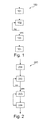
- Fig. 1 illustrates a flow chart diagram describing the method 100 of determining a reliability of a radio frequency link according to an exemplary embodiment of the invention in more detail.
- this Fig. the range of the peak-to-peak voltage at the beginning of the RF communication is illustrated.
- the RF level detector When the NFC device is initialized in card mode, the RF level detector is initialized with a minimum value, the initial threshold value (101). The RF level detector detects whether there is an RF field present or not (102). If an RF field is seen, the detector will try to know the current range of RF peak-to-peak voltage (103). To determine it, the RF level detector will be initialized from a top value to a minimum value. There may be for example 8 pre-selected threshold values for the RF level detector. These threshold values may be stored in a memory unit of the NFC device. The RF level detector goes through each value starting from 7 to 0. 7 means the maximum level is set and once peak-to-peak voltage is below that value, the RF level detection bit triggers.
- the RF level detector will notify it (104). Subsequently, a notification signal may be send to the control unit of the NFC device. Once this threshold is known, this value is readable in the control unit and the RF level detector may be re-initialized with a default value (minimum value) to know if the target is removed from the external RF field.
- Fig. 2 illustrates a flow chart diagram describing the method 200 of determining a reliability of a radio frequency link according to a further exemplary embodiment of the invention. In this Fig., monitoring the range of the peak-to-peak voltage during the RF communication is illustrated.
- the RF level detector When the NFC device is initialized in card mode, the RF level detector is initialized with a minimum value (201). If an RF field is seen, the NFC device will try to know the current range of the RF peak-to-peak voltage. To determine it, the RF level detector will be initialized from the top value to the minimum value (202). The RF level detector goes through ("no") every pre-defined setting (see table above) until this signal goes up (“yes"). As soon as the external RF field is lower than the pre-defined threshold, a signal status (output of the RF level detector) is sent to the control unit (203). That signal goes high as soon as the pre-defined peak-to-peak value (corresponding to setting [2:0]) is lower than the signal arriving on the RF level detector (203).
- this threshold is readable in the control unit.
- the current threshold value will be kept and each XXXms, this value will be re-evaluated with steps 202 and 203. If the RF level detector notifies that the RF seen is different than the latest known threshold, the system updates the readable value (204). Then, the re-evaluation will be repeated.
- Fig. 4 illustrates a communication system 400 comprising the device of Fig. 3 in combination with a reading device according to an exemplary embodiment of the invention.
- the communication system 400 comprises a reader device 420 and an NFC device 440.
- the reader 420 comprises a processor 422 (such as a microprocessor or a central processing unit) which is communicatively coupled with an emitter antenna 424 and a receiver antenna 426.
- the emitter antenna 424 is capable of transmitting a communication message 428 to the NFC device 440.
- the receiver antenna 426 is capable of receiving a communication message 430 from the NFC device 440.
- the transmission antenna 424 and the receiver antenna 426 are illustrated as two different antennas in Fig. 4 , alternative embodiments may also use a single common shared transceiver antenna.
- the antennas 424, 426 are electrically coupled with the processor 422 so that data may be sent from the processor 422 to the transmission antenna 424 for transmission as a communication message 428.
- a communication message 430 received by the receiver antenna 426 may also be analyzed and processed by the processor 422.
- a storage unit 432 such as a semiconductor memory is coupled with the processor 422 so as to allow storing data accessible for the processor 422.
- an input/output unit 434 is shown which allows a user to operate the reader device 420.
- the input/output unit 434 may comprise input elements such as buttons, a keypad, a joystick or the like. Via such input elements, a user may input commands to the reader device 420.
- the input/output unit 434 may comprise a display unit such as a liquid crystal display allowing displaying results of the reading procedure of the reader device 420 visible for a user.
- the NFC device 440 comprises a transmission and receiver antenna 436, a processor 442 such as a microprocessor and a radio frequency level detector 438.
- the radio frequency level detector 438 and the processor or control unit 442 may be monolithically integrated in an integrated circuit (IC) which can be connected to the antenna 436 and attached to a support such as a piece of fabric.
- IC integrated circuit
- the communication messages 428, 330 can be exchanged in a wireless manner between the entities 420, 440.
- the control unit 401 may correspond to the control unit 302 of Fig. 3 , and may comprise also the receiving unit for receiving the initial threshold value.
- the same applies to the radio frequency level detector 301 of Fig. 3 which may correspond to the radio frequency level detector 402.
- the control unit, the receiving unit and the radio frequency level detector may also be integrated in one single unit.
Landscapes
- Engineering & Computer Science (AREA)
- Computer Networks & Wireless Communication (AREA)
- Signal Processing (AREA)
- Near-Field Transmission Systems (AREA)
Priority Applications (1)
| Application Number | Priority Date | Filing Date | Title |
|---|---|---|---|
| EP11290208A EP2518905A1 (fr) | 2011-04-28 | 2011-04-28 | Détermination de la fiabilité d'une liaison de fréquence radio |
Applications Claiming Priority (1)
| Application Number | Priority Date | Filing Date | Title |
|---|---|---|---|
| EP11290208A EP2518905A1 (fr) | 2011-04-28 | 2011-04-28 | Détermination de la fiabilité d'une liaison de fréquence radio |
Publications (1)
| Publication Number | Publication Date |
|---|---|
| EP2518905A1 true EP2518905A1 (fr) | 2012-10-31 |
Family
ID=45002187
Family Applications (1)
| Application Number | Title | Priority Date | Filing Date |
|---|---|---|---|
| EP11290208A Withdrawn EP2518905A1 (fr) | 2011-04-28 | 2011-04-28 | Détermination de la fiabilité d'une liaison de fréquence radio |
Country Status (1)
| Country | Link |
|---|---|
| EP (1) | EP2518905A1 (fr) |
Cited By (2)
| Publication number | Priority date | Publication date | Assignee | Title |
|---|---|---|---|---|
| EP2816736A1 (fr) * | 2013-06-18 | 2014-12-24 | ST-Ericsson SA | Chargement binaire adaptatif dans NFC |
| CN113708852A (zh) * | 2020-05-21 | 2021-11-26 | 华为技术有限公司 | 一种天线的在位检测方法和装置 |
Citations (4)
| Publication number | Priority date | Publication date | Assignee | Title |
|---|---|---|---|---|
| US20040179588A1 (en) * | 2003-03-11 | 2004-09-16 | Stephen Kuffner | Method and apparatus for electronic item identification in a communication system using known source parameters |
| US20070247286A1 (en) * | 2006-03-31 | 2007-10-25 | Symbol Technologies, Inc. | RFID tag receive signal strength indicator |
| US20090002176A1 (en) * | 2007-06-28 | 2009-01-01 | Symbol Technologies, Inc. | Backscatter Limited Tags |
| US20100060432A1 (en) * | 2008-09-05 | 2010-03-11 | Johannes Albertus Van Niekerk | Battery Assisted Tag and RFID System |
-
2011
- 2011-04-28 EP EP11290208A patent/EP2518905A1/fr not_active Withdrawn
Patent Citations (4)
| Publication number | Priority date | Publication date | Assignee | Title |
|---|---|---|---|---|
| US20040179588A1 (en) * | 2003-03-11 | 2004-09-16 | Stephen Kuffner | Method and apparatus for electronic item identification in a communication system using known source parameters |
| US20070247286A1 (en) * | 2006-03-31 | 2007-10-25 | Symbol Technologies, Inc. | RFID tag receive signal strength indicator |
| US20090002176A1 (en) * | 2007-06-28 | 2009-01-01 | Symbol Technologies, Inc. | Backscatter Limited Tags |
| US20100060432A1 (en) * | 2008-09-05 | 2010-03-11 | Johannes Albertus Van Niekerk | Battery Assisted Tag and RFID System |
Cited By (3)
| Publication number | Priority date | Publication date | Assignee | Title |
|---|---|---|---|---|
| EP2816736A1 (fr) * | 2013-06-18 | 2014-12-24 | ST-Ericsson SA | Chargement binaire adaptatif dans NFC |
| CN113708852A (zh) * | 2020-05-21 | 2021-11-26 | 华为技术有限公司 | 一种天线的在位检测方法和装置 |
| CN113708852B (zh) * | 2020-05-21 | 2022-11-11 | 华为技术有限公司 | 一种天线的在位检测方法和装置 |
Similar Documents
| Publication | Publication Date | Title |
|---|---|---|
| US8723648B2 (en) | Method and system for locating a hand-held terminal | |
| EP3422588A1 (fr) | Architecture de détection de carte pour communications en champ proche | |
| CN104939804B (zh) | 生理参数量测系统及方法 | |
| US9268980B2 (en) | Wireless tag communication device and wireless tag communication program | |
| KR102334330B1 (ko) | 안테나 스위칭을 지원하기 위한 무선 통신 회로 및 그를 포함하는 장치 | |
| KR20170084563A (ko) | 무선 통신 시스템에서 전자 장치 설치 장치 및 방법 | |
| US11432214B2 (en) | Method for network state identification and electronic device therefor | |
| JP2008125077A (ja) | 無線周波数識別システム | |
| US20180150666A1 (en) | Temperature Data Processing Method and System | |
| CN106940437B (zh) | 一种室内定位方法、设备及系统 | |
| KR101637483B1 (ko) | 거리 및 친밀도를 이용한 주변 장치 인식 장치 및 방법 | |
| KR20150094153A (ko) | 전자 장치 및 전자 장치의 네트워크 연결 방법 | |
| KR102448560B1 (ko) | 유도성 커플링을 통해 통신하는 통신 디바이스를 동작시키는 방법 및 시스템 | |
| US11201492B2 (en) | Detecting objects placed on wireless charger | |
| US10236721B2 (en) | Power reception apparatus, determination method, and program | |
| JPWO2012053203A1 (ja) | 近距離無線通信装置 | |
| US20230385570A1 (en) | Information processing apparatus, information processing method, and computer-readable storage medium | |
| EP2518905A1 (fr) | Détermination de la fiabilité d'une liaison de fréquence radio | |
| US9985475B2 (en) | Power supply apparatus and method | |
| US11128348B2 (en) | Operating method of electronic device performing near field communication functions | |
| KR20180037499A (ko) | 무선 전력 송신 장치 | |
| CN102395897B (zh) | 通过利用射频技术的区域标识和区域限定 | |
| US20160105309A1 (en) | Configuration of nfc routers for p2p communication | |
| US20170208548A1 (en) | Portable Device Control Method and Device | |
| CN111521375B (zh) | 伽马值的确定方法及装置 |
Legal Events
| Date | Code | Title | Description |
|---|---|---|---|
| PUAI | Public reference made under article 153(3) epc to a published international application that has entered the european phase |
Free format text: ORIGINAL CODE: 0009012 |
|
| AK | Designated contracting states |
Kind code of ref document: A1 Designated state(s): AL AT BE BG CH CY CZ DE DK EE ES FI FR GB GR HR HU IE IS IT LI LT LU LV MC MK MT NL NO PL PT RO RS SE SI SK SM TR |
|
| AX | Request for extension of the european patent |
Extension state: BA ME |
|
| STAA | Information on the status of an ep patent application or granted ep patent |
Free format text: STATUS: THE APPLICATION IS DEEMED TO BE WITHDRAWN |
|
| 18D | Application deemed to be withdrawn |
Effective date: 20130503 |