EP2519015B1 - Verfahren zum Markieren von Signalen, die bei der Leckdetektion und -messung in xDSL-Datenübertragungsnetzen verwendet werden, sowie Vorrichtung zur Detektion und/oder Messung von mit diesem Verfahren markierten Leckquellen - Google Patents
Verfahren zum Markieren von Signalen, die bei der Leckdetektion und -messung in xDSL-Datenübertragungsnetzen verwendet werden, sowie Vorrichtung zur Detektion und/oder Messung von mit diesem Verfahren markierten Leckquellen Download PDFInfo
- Publication number
- EP2519015B1 EP2519015B1 EP12460019.8A EP12460019A EP2519015B1 EP 2519015 B1 EP2519015 B1 EP 2519015B1 EP 12460019 A EP12460019 A EP 12460019A EP 2519015 B1 EP2519015 B1 EP 2519015B1
- Authority
- EP
- European Patent Office
- Prior art keywords
- signal
- tagging
- leakage
- xdsl
- measurement
- Prior art date
- Legal status (The legal status is an assumption and is not a legal conclusion. Google has not performed a legal analysis and makes no representation as to the accuracy of the status listed.)
- Active
Links
- 238000000034 method Methods 0.000 title claims description 34
- 238000005259 measurement Methods 0.000 title claims description 27
- 238000001514 detection method Methods 0.000 title claims description 25
- 230000005540 biological transmission Effects 0.000 title claims description 18
- 238000001228 spectrum Methods 0.000 claims description 21
- 238000006243 chemical reaction Methods 0.000 claims description 3
- 238000005070 sampling Methods 0.000 claims description 3
- 238000000605 extraction Methods 0.000 claims 1
- 238000012360 testing method Methods 0.000 description 7
- 238000004891 communication Methods 0.000 description 5
- 238000005516 engineering process Methods 0.000 description 5
- 230000002452 interceptive effect Effects 0.000 description 4
- 230000008569 process Effects 0.000 description 4
- 238000010586 diagram Methods 0.000 description 3
- 230000004807 localization Effects 0.000 description 3
- 230000004048 modification Effects 0.000 description 3
- 238000012986 modification Methods 0.000 description 3
- 230000005855 radiation Effects 0.000 description 3
- 230000035945 sensitivity Effects 0.000 description 3
- RYGMFSIKBFXOCR-UHFFFAOYSA-N Copper Chemical compound [Cu] RYGMFSIKBFXOCR-UHFFFAOYSA-N 0.000 description 2
- 229910052802 copper Inorganic materials 0.000 description 2
- 239000010949 copper Substances 0.000 description 2
- 238000012937 correction Methods 0.000 description 2
- 230000005684 electric field Effects 0.000 description 2
- 230000005670 electromagnetic radiation Effects 0.000 description 2
- 101150012579 ADSL gene Proteins 0.000 description 1
- 102100020775 Adenylosuccinate lyase Human genes 0.000 description 1
- 108700040193 Adenylosuccinate lyases Proteins 0.000 description 1
- 230000009471 action Effects 0.000 description 1
- 230000008901 benefit Effects 0.000 description 1
- 230000033228 biological regulation Effects 0.000 description 1
- 230000008878 coupling Effects 0.000 description 1
- 238000010168 coupling process Methods 0.000 description 1
- 238000005859 coupling reaction Methods 0.000 description 1
- 230000006870 function Effects 0.000 description 1
- 230000036039 immunity Effects 0.000 description 1
- 238000012545 processing Methods 0.000 description 1
- 238000003672 processing method Methods 0.000 description 1
- 230000001902 propagating effect Effects 0.000 description 1
- 238000013139 quantization Methods 0.000 description 1
- 230000004044 response Effects 0.000 description 1
- 238000000926 separation method Methods 0.000 description 1
- 230000008054 signal transmission Effects 0.000 description 1
- 230000009897 systematic effect Effects 0.000 description 1
Images

Classifications
-
- H—ELECTRICITY
- H04—ELECTRIC COMMUNICATION TECHNIQUE
- H04M—TELEPHONIC COMMUNICATION
- H04M11/00—Telephonic communication systems specially adapted for combination with other electrical systems
- H04M11/06—Simultaneous speech and data transmission, e.g. telegraphic transmission over the same conductors
- H04M11/062—Simultaneous speech and data transmission, e.g. telegraphic transmission over the same conductors using different frequency bands for speech and other data
Definitions
- the present invention relates to a method of tagging signals used for leakage detection and measurement in data transmission networks as well as apparatus for the detection and/or measurement of leakage sources tagged with this method.
- Digital subscriber loop technology is used for information transmission over a subscriber (local) loop.
- the loop connects a subscriber's terminal endpoint (TE), installed at home or in the office, with a telecommunications provider's central office (CO) serving the terminal endpoint.
- TE subscriber's terminal endpoint
- CO central office
- a subscriber loop is a symmetric transmission line made of an ushielded pair of twisted copper wires.
- Many of currently used subscriber loops have been designed for analog phone services (POTS - Plain Old Telephone Service).
- POTS - Plain Old Telephone Service POTS - Plain Old Telephone Service
- With the xDSL technology such a loop can be used for fast data transmission, access to the Internet and other multimedia services.
- the transmission speed can reach a few dozen Mb/s depending on the xDSL technology variant.
- the letter "x" stands for the technology variant, e.g., ADSL, VDSL or HDSL.
- the spectrum of xDSL signals may occupy a bandwidth up to 30 MHz (VDSL2; this limit can be increased in the future). This broad spectrum shares frequency allocation with conventional radio communication systems (AM broadcasting) and radio amateurs.
- One of the problems faced by the xDSL system operators is signal leakage, which is undesirable electromagnetic radiation from a transmission line.
- An unshielded transmission line shown in FIG. 1 which is a twisted pair of wires, generates relatively high electromagnetic radiation.
- shielded twisted pair cables are often used. The shield of such cables can be damaged and such a damage can increase the radiation level.
- An additional source of leakage can be unloaded network branches, corroded or damaged connectors, bad quality or damaged network splitters or network modifications done by unqualified persons.
- each discontinuity radiating the electromagnetic energy from an xDSL network forms a receiving antenna through which energy from terrestrial transmitters and other radio frequency sources (so called ingress) can enter the network.
- Most of leakage sources are also ingress sources. Ingress deteriorates the quality of the signals propagating in a xDSL network, reducing the transmission speed or the distance between a subscriber terminal and CO.
- EMC Electromagnetic Compatibility
- a meter or detector for leakage measurement from xDSL networks should consist of an antenna and a receiver that is tuned to a frequency (referred as a test frequency) in the xDSL signal bandwidth. Such a device usually has a signal strength (the absolute value of the electric field intensity) measurement circuit.
- a typical method of leakage source detection requires a signal strength measurement on the test frequency. If the signal strength measurement circuit detects a relatively large amplitude signal at a particular location, a leak may be indicated in or near that localization.
- a technician may use a leakage detector to pinpoint the source of a leak. A corrective action may be taken to remove the leak source from the network.
- the methods of tagging leakage signals from xDSL networks are unknown.
- An example of such device is the HST-3000C meter manufactured by JDSU, USA.
- the meter has a spectrum analyzer.
- the spectrum analyzer is in the Span Zero mode and analyzes the received signals in the time domain.
- the received signal is considered as a leak when the meter recognizes (automatically or by a technician - depending on the operation mode) that the signal in the time domain has a pattern typical for a xDSL system.
- the described method is not effective when other xDSL networks belonging to various operators have been deployed in the same area.
- the described method of leakage detection does not allow to unambiguously determine the network from which the leak comes from.
- the methods of leakage detection and measurement in cable TV networks (CATV) using coaxial cables are commonly known.
- the U.S.A. patents US 6,310,646 and US 6,307,593 can be good examples. Both patents describe the method of tagging leakage signals from CATV networks. However, these methods cannot be applied for xDSL networks, because they are based on the specific features of the analog TV signal. Moreover, both methods modify the useful (carrying information) signal transmitted in CATV networks, so they can decrease the quality of received signals.
- the US 6,118,975 patent describes leakage tagging in CATV networks by means of the tagging signal inserted into the network. The tagging signal has a very broadband frequency spectrum and requires one unused 8 MHz TV channel.
- the method of tagging the signals used for leakage detection and/or measurement in networks with digital subscriber loops (xDSL) using additional signals transmitted in these networks and carrying the tagging information is based on placing a narrowband tagging signal (or signals) in chosen parts of the frequency spectrum which are close to the spectrum occupied by the xDSL signals transmitted in a network.
- the tagging signal (or signals) is narrowband, with the bandwidth being smaller than 20 kHz.
- the apparatus for leakage detection and/or measurements from xDSL networks, tagged according to the method presented in the invention, which uses the principle of signal reception based on frequency conversion, has a narrowband filter (or filters) with a bandwidth smaller than 20 kHz for the separation of the tagging signals.
- the filter output is connected with the microprocessor input.
- the microprocessor is connected with an antenna switch, an amplifier, a voltage controlled generator, a display and a keyboard and has been programmed for sampling and quantizing of the input signal and for the detection of the spectrum components carrying the tagging information.
- the microprocessor uses the fast Fourier transform (FFT) or the discrete cosine transform (DCT) algorithm.
- FFT fast Fourier transform
- DCT discrete cosine transform
- the innovation of the present invention lies in the placement of a tagging signal within the bandwidth which is in close proximity of the bandwidth occupied by a digital signal used for the transmission of services in a xDSL network.
- the tagging signals can be inserted by means of an external generator, so called a tagger, or can be created in the terminal end-point by means of the modified firmware of the terminal.
- an external generator so called a tagger
- At both ends of the bandwidth occupied by a xDSL signal there are always free frequency bands. There is no useful energy (coming from the modulation process) generated by xDSL equipment and transmitted in these bands. If a narrowband tagging signal (or signals) are placed in the free bands, the xDSL signal quality will be unaffected.
- the tagging signal or signals will propagate in a transmission line together with the xDSL signal.
- any narrowband signal with any type of analog or digital modulation can be used as a tagging signal.
- a tagging signal can be a sinusoidal wave which is modulated with amplitude.
- the modulation frequency is low, in the range from 1 to 50 Hz, in order to minimize the bandwidth occupied by the signal.
- the usage of a sinusoidal wave simplifies the measurement of the absolute magnitude of the leakage by a leakage meter or detector.
- the narrowband tagging signal (not only sinusoidal) can be extracted in the leakage meter or detector by means of, for example, the fast Fourier transform (FFT), the discrete cosine transform (DCT), or a very narrow bandpass filter, which attenuates the spectrum of the signals not lying in the tagging signal band.
- FFT fast Fourier transform
- DCT discrete cosine transform
- the narrowband tagging signal substantially improves the accuracy of leakage magnitude measurements.
- the above described sinusoidal signal with amplitude modulation is one possible form of the tagging signal.
- a greater number of tagging signals which can be used in the methods described herein, increases the leakage meter/detector immunity to interfering signals and reduces the likelihood that the detected leak comes from a network other than the network under test.
- the advantage of the invention is the possibility of fast and effective leakage and ingress source localization. It simplifies maintaining the high quality of signals transmitted in xDSL networks.
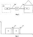
- a typical system of a digital subscriber loop shown in Fig. 1 , consists of the following parts: a communication node (central office - CO ), belonging to a service provider, in which there is an end terminal TE, a transmission network made of a pair of twisted copper wires TW, an optional network terminal NT, and an end terminal TE placed at subscriber's home or office.
- the terminal TE provides conversion, modulation/demodulation, and data transmission/reception.
- the transmission line TW may have too high attenuation and this is why an optional device NT is sometimes used to amplify a signal, so the TW length can be extended.
- Fig. 2 presents an exemplary frequency spectrum (distribution of energy E in terms of frequency f) of a xDSL signal.
- the spectrum consists of a DL part, which serves for transmission from a communication node CO to a subscriber's terminal TE, and an UL part for transmission in the reverse direction.
- a narrowband tagging signal TS may be placed in the spectrum part which separates UL from DL or above the whole band occupied by an xDSL signal. Due to better radiation it is advised to use higher frequencies for leakage tagging.
- Fig. 3 presents a typical xDSL network with a tagger T installed for leakage tagging using the method according to the invention.
- the tagging signal is inserted into the network via an inserter (coupling device) I which can be close to a subscriber's terminal or a communication node CO (marked with a dashed line).
- a leakage source LS radiates electromagnetic energy which is received by a leakage meter LM.
- the leakage meter LM can receive the interfering signal.
- the interfering signal does not contain the tagging information, so the received signal will not be recognized as a leak from the network under test.
- the process of leakage detection using the method according to the invention is as follows.
- the tagger T is connected to that part of a xDSL network which requires testing or is suspected as radiating excessive leakage.
- the choice of the suspected part of a network can be based on an earlier measurement of a power level which has given higher levels above the noise floor in the part of the spectrum used for data transmission in this network. Such a measurement can be done during a mobile patrol with a car antenna and a spectrum analyzer which can be built in a leakage meter/detector or be a stand-alone device.
- a technician After switching on a tagging signal, a technician performs a mobile patrol, during which he determines geographical coordinates of the places where a leakage meter or detector has detected the tagging signal from the network under test with the amplitude higher than the established limit. In the next step, the technician exactly localizes the leak sources and fix them during a pedestrian patrol.
- FIG. 4 presents a block diagram of the leakage meter and/or detector which uses the method of signal tagging according to the invention.
- the apparatus for leakage measurement and/or detection according to the method described herein has good sensitivity, dynamic range and the detection ability of tagging signals.
- the meter and/or detector has a built-in internal antenna and allows for the connection of external measurement antennas (e.g., kept in hand or placed on a vehicle roof).
- the signal received by the antenna is amplified in the input low noise amplifier LNA.
- the amplified signal appears at the input of the mixer MX.
- the second input of the mixer is connected to the variable local oscillator LO.
- the mixer MX shifts the input signal on the frequency axis by the frequency of the local oscillator signal.
- the signal at the mixer output has the frequency lying within the bandwidth of the narrowband filter F (the bandwidth is from a few kHz up to several kHz).
- the filter F attenuates all the signals lying outside the narrow band with the tagging signal and coming from the xDSL network under test, other networks or terrestrial sources which can interfere with the tagging signal.
- the parameters of the filter F (bandwidth, frequency response slope) have substantial influence on the correct detection and measurement of the leaking signal.
- the output signal of the filter F enters the input of the microprocessor MIC.
- the microprocessor MIC has control functions (it controls the antenna switch AS, the amplifier LNA, the oscillator LO, the screen S, and the keyboard K ) and digitally processes the signals.
- the digital signal processing in the microprocessor MIC comprises sampling and quantization of the input signal as well as the recognition of the spectrum components carrying the tagging information.
- the detection of the spectrum components with the tagging information is based on the fast Fourier transform (FFT) algorithm. Due to this processing method, a very good sensitivity of tagging signal detection can be achieved.
- FFT fast Fourier transform
- the microprocessor MIC also determines the amplitude of the received leakage signal.
- Information about the leak magnitude and the presence of the tagging signal is displayed on the screen of the apparatus.
- the usage of the microprocessor allows for the correction of the systematic errors.
- the correction values added to the measurement results are saved in the microprocessor memory during the periodical calibration of the meter/ detector.
- An alternative example of the leakage meter/detector embodiment according to the invention has a different microprocessor program, which uses the discrete cosine transform (DCT) for detection of the spectrum components carrying the tagging information.
- DCT discrete cosine transform
Landscapes
- Engineering & Computer Science (AREA)
- Computer Networks & Wireless Communication (AREA)
- Signal Processing (AREA)
- Monitoring And Testing Of Transmission In General (AREA)
- Radar Systems Or Details Thereof (AREA)
Claims (5)
- Verfahren zur Kennzeichnung der Signale zur Erkennung und/oder Messung von Leckstellen in Datenübertragungsnetzen mit digitaler xDSL-Teilnehmerschleife, unter Einsatz von zusätzlichen Signalen, die über diese Netze gesendet werden und Kennzeichnungsinformationen übertragen, dadurch gekennzeichnet, dass ein kennzeichnendes Schmalbandsignal bzw. -signale mit einer Bandbreite von weniger als 20 kHz in dem/den ungenutzten Teil(en) des Frequenzspektrums des xDSL-Signals oder in der Nähe des Frequenzspektrums des xDSL-Signals angeordnet wird/werden.
- Verfahren nach Anspruch 1, dadurch gekennzeichnet, dass ein kennzeichnendes Schmalbandsignal mit einer Bandbreite von weniger als 20 kHz eingesetzt wird.
- Gerät zur Erkennung und/oder Messung von Leckagequellen in Datennetzen mit digitaler xDSL-Teilnehmerschleife, die nach Verfahren nach Anspruch 1 gekennzeichnet ist, bei dem ein Empfang von Signalen mit Frequenzwandlung verwendet wird, mit einem Schmalbandfilter oder Filtern zur Trennung von kennzeichnenden Signalen, dadurch gekennzeichnet, dass jedes Schmalbandfilter (F) eine Bandbreite von weniger als 20 kHz hat und der Filterausgang mit dem Eingang eines Mikroprozessors (MIC) verbunden ist; der Mikroprozessor (MIC) ist auch mit einem Antennenumschalter (AS), einem Verstärker (LNA), einem lokalen Oszillator mit veränderbarer Frequenz (LO), einem Bildschirm (S) und einer Tastatur (K) verbunden sowie für die Entnahme von Proben und Quantisierung des Eingangssignals als auch Erkennung von Spektrumkomponenten, die kennzeichnende Informationen übertragen, programmiert.
- Gerät nach Anspruch 3, dadurch gekennzeichnet, dass sein Mikroprozessor (MIC) die schnelle Fourier-Transformation (FFT) verwendet.
- Gerät nach Anspruch 3, dadurch gekennzeichnet, dass sein Mikroprozessor (MIC) die diskrete Kosinustransformation (DCT) verwendet.
Applications Claiming Priority (1)
| Application Number | Priority Date | Filing Date | Title |
|---|---|---|---|
| PL394724A PL219681B1 (pl) | 2011-04-30 | 2011-04-30 | Sposób znakowania sygnałów używanych do wykrywania i pomiaru wycieków w sieciach transmisji danych xDSL oraz urządzenie do wykrywania i/lub pomiaru wycieków znakowanych tym sposobem |
Publications (2)
| Publication Number | Publication Date |
|---|---|
| EP2519015A1 EP2519015A1 (de) | 2012-10-31 |
| EP2519015B1 true EP2519015B1 (de) | 2019-05-08 |
Family
ID=46125382
Family Applications (1)
| Application Number | Title | Priority Date | Filing Date |
|---|---|---|---|
| EP12460019.8A Active EP2519015B1 (de) | 2011-04-30 | 2012-04-27 | Verfahren zum Markieren von Signalen, die bei der Leckdetektion und -messung in xDSL-Datenübertragungsnetzen verwendet werden, sowie Vorrichtung zur Detektion und/oder Messung von mit diesem Verfahren markierten Leckquellen |
Country Status (3)
| Country | Link |
|---|---|
| US (1) | US20120275503A1 (de) |
| EP (1) | EP2519015B1 (de) |
| PL (1) | PL219681B1 (de) |
Family Cites Families (4)
| Publication number | Priority date | Publication date | Assignee | Title |
|---|---|---|---|---|
| US6310646B1 (en) * | 1996-11-29 | 2001-10-30 | Wavetek Corporation | Method and apparatus for measuring a radio frequency signal having program information and control information |
| US6307593B1 (en) * | 1997-10-03 | 2001-10-23 | Wavetek Corporation | Pulsed leakage tagging signal |
| US6118975A (en) * | 1997-12-02 | 2000-09-12 | Wavetek Wandel Goltermann, Inc. | Method and apparatus for leakage detection using pulsed RF tagging signal |
| US7395548B2 (en) * | 2001-07-26 | 2008-07-01 | Comsonics, Inc. | System and method for signal validation and leakage detection |
-
2011
- 2011-04-30 PL PL394724A patent/PL219681B1/pl unknown
-
2012
- 2012-04-04 US US13/438,986 patent/US20120275503A1/en not_active Abandoned
- 2012-04-27 EP EP12460019.8A patent/EP2519015B1/de active Active
Non-Patent Citations (1)
| Title |
|---|
| None * |
Also Published As
| Publication number | Publication date |
|---|---|
| PL219681B1 (pl) | 2015-06-30 |
| EP2519015A1 (de) | 2012-10-31 |
| US20120275503A1 (en) | 2012-11-01 |
| PL394724A1 (pl) | 2012-11-05 |
Similar Documents
| Publication | Publication Date | Title |
|---|---|---|
| US8856850B2 (en) | Method of tagging signals used for leakage detection and measurement in cable television networks and apparatus for detection and/or measurement of leakage sources tagged with this method | |
| US10404388B2 (en) | Detecting signal leakage in cable networks | |
| US10291333B2 (en) | Measurement of voltage standing wave ratio of antenna system | |
| CA2656025C (en) | Detection and monitoring of partial discharge of a power line | |
| US11856182B2 (en) | Icon-based home certification, in-home leakage testing, and antenna matching pad | |
| US20230269131A1 (en) | High resolution time domain reflectometry (tdr) in fault location measurement in a cable network | |
| US20030022645A1 (en) | System and method for signal validation and leakage detection | |
| US6433905B1 (en) | Frequency agile transponder | |
| EP2519015B1 (de) | Verfahren zum Markieren von Signalen, die bei der Leckdetektion und -messung in xDSL-Datenübertragungsnetzen verwendet werden, sowie Vorrichtung zur Detektion und/oder Messung von mit diesem Verfahren markierten Leckquellen | |
| US6980163B2 (en) | Signal leakage detector | |
| US9577769B2 (en) | Built-in self-test technique for detection of imperfectly connected antenna in OFDM transceivers | |
| WO1995025390A1 (en) | A method and apparatus for measuring digital radio interference | |
| Prukner et al. | Frequency Study in the Cable Television Systems and Terrestrial Television Systems | |
| Prukner et al. | Measurement of the Shielding Effectiveness of Passive Cable Television Elements | |
| Cohen et al. | The emission and interference aspects of broad band over power lines to HF receivers |
Legal Events
| Date | Code | Title | Description |
|---|---|---|---|
| PUAI | Public reference made under article 153(3) epc to a published international application that has entered the european phase |
Free format text: ORIGINAL CODE: 0009012 |
|
| AK | Designated contracting states |
Kind code of ref document: A1 Designated state(s): AL AT BE BG CH CY CZ DE DK EE ES FI FR GB GR HR HU IE IS IT LI LT LU LV MC MK MT NL NO PL PT RO RS SE SI SK SM TR |
|
| AX | Request for extension of the european patent |
Extension state: BA ME |
|
| 17P | Request for examination filed |
Effective date: 20130402 |
|
| STAA | Information on the status of an ep patent application or granted ep patent |
Free format text: STATUS: EXAMINATION IS IN PROGRESS |
|
| 17Q | First examination report despatched |
Effective date: 20180205 |
|
| REG | Reference to a national code |
Ref country code: DE Ref legal event code: R079 Ref document number: 602012059818 Country of ref document: DE Free format text: PREVIOUS MAIN CLASS: H04N0017000000 Ipc: H04M0011060000 |
|
| GRAP | Despatch of communication of intention to grant a patent |
Free format text: ORIGINAL CODE: EPIDOSNIGR1 |
|
| STAA | Information on the status of an ep patent application or granted ep patent |
Free format text: STATUS: GRANT OF PATENT IS INTENDED |
|
| RIC1 | Information provided on ipc code assigned before grant |
Ipc: H04M 11/06 20060101AFI20180926BHEP |
|
| INTG | Intention to grant announced |
Effective date: 20181023 |
|
| GRAS | Grant fee paid |
Free format text: ORIGINAL CODE: EPIDOSNIGR3 |
|
| GRAA | (expected) grant |
Free format text: ORIGINAL CODE: 0009210 |
|
| STAA | Information on the status of an ep patent application or granted ep patent |
Free format text: STATUS: THE PATENT HAS BEEN GRANTED |
|
| AK | Designated contracting states |
Kind code of ref document: B1 Designated state(s): AL AT BE BG CH CY CZ DE DK EE ES FI FR GB GR HR HU IE IS IT LI LT LU LV MC MK MT NL NO PL PT RO RS SE SI SK SM TR |
|
| REG | Reference to a national code |
Ref country code: GB Ref legal event code: FG4D |
|
| REG | Reference to a national code |
Ref country code: CH Ref legal event code: EP Ref country code: AT Ref legal event code: REF Ref document number: 1132031 Country of ref document: AT Kind code of ref document: T Effective date: 20190515 |
|
| REG | Reference to a national code |
Ref country code: DE Ref legal event code: R096 Ref document number: 602012059818 Country of ref document: DE Ref country code: IE Ref legal event code: FG4D |
|
| REG | Reference to a national code |
Ref country code: NL Ref legal event code: MP Effective date: 20190508 |
|
| REG | Reference to a national code |
Ref country code: LT Ref legal event code: MG4D |
|
| PG25 | Lapsed in a contracting state [announced via postgrant information from national office to epo] |
Ref country code: SE Free format text: LAPSE BECAUSE OF FAILURE TO SUBMIT A TRANSLATION OF THE DESCRIPTION OR TO PAY THE FEE WITHIN THE PRESCRIBED TIME-LIMIT Effective date: 20190508 Ref country code: HR Free format text: LAPSE BECAUSE OF FAILURE TO SUBMIT A TRANSLATION OF THE DESCRIPTION OR TO PAY THE FEE WITHIN THE PRESCRIBED TIME-LIMIT Effective date: 20190508 Ref country code: ES Free format text: LAPSE BECAUSE OF FAILURE TO SUBMIT A TRANSLATION OF THE DESCRIPTION OR TO PAY THE FEE WITHIN THE PRESCRIBED TIME-LIMIT Effective date: 20190508 Ref country code: LT Free format text: LAPSE BECAUSE OF FAILURE TO SUBMIT A TRANSLATION OF THE DESCRIPTION OR TO PAY THE FEE WITHIN THE PRESCRIBED TIME-LIMIT Effective date: 20190508 Ref country code: NL Free format text: LAPSE BECAUSE OF FAILURE TO SUBMIT A TRANSLATION OF THE DESCRIPTION OR TO PAY THE FEE WITHIN THE PRESCRIBED TIME-LIMIT Effective date: 20190508 Ref country code: NO Free format text: LAPSE BECAUSE OF FAILURE TO SUBMIT A TRANSLATION OF THE DESCRIPTION OR TO PAY THE FEE WITHIN THE PRESCRIBED TIME-LIMIT Effective date: 20190808 Ref country code: AL Free format text: LAPSE BECAUSE OF FAILURE TO SUBMIT A TRANSLATION OF THE DESCRIPTION OR TO PAY THE FEE WITHIN THE PRESCRIBED TIME-LIMIT Effective date: 20190508 Ref country code: PT Free format text: LAPSE BECAUSE OF FAILURE TO SUBMIT A TRANSLATION OF THE DESCRIPTION OR TO PAY THE FEE WITHIN THE PRESCRIBED TIME-LIMIT Effective date: 20190908 Ref country code: FI Free format text: LAPSE BECAUSE OF FAILURE TO SUBMIT A TRANSLATION OF THE DESCRIPTION OR TO PAY THE FEE WITHIN THE PRESCRIBED TIME-LIMIT Effective date: 20190508 |
|
| PG25 | Lapsed in a contracting state [announced via postgrant information from national office to epo] |
Ref country code: BG Free format text: LAPSE BECAUSE OF FAILURE TO SUBMIT A TRANSLATION OF THE DESCRIPTION OR TO PAY THE FEE WITHIN THE PRESCRIBED TIME-LIMIT Effective date: 20190808 Ref country code: RS Free format text: LAPSE BECAUSE OF FAILURE TO SUBMIT A TRANSLATION OF THE DESCRIPTION OR TO PAY THE FEE WITHIN THE PRESCRIBED TIME-LIMIT Effective date: 20190508 Ref country code: LV Free format text: LAPSE BECAUSE OF FAILURE TO SUBMIT A TRANSLATION OF THE DESCRIPTION OR TO PAY THE FEE WITHIN THE PRESCRIBED TIME-LIMIT Effective date: 20190508 Ref country code: GR Free format text: LAPSE BECAUSE OF FAILURE TO SUBMIT A TRANSLATION OF THE DESCRIPTION OR TO PAY THE FEE WITHIN THE PRESCRIBED TIME-LIMIT Effective date: 20190809 |
|
| REG | Reference to a national code |
Ref country code: AT Ref legal event code: MK05 Ref document number: 1132031 Country of ref document: AT Kind code of ref document: T Effective date: 20190508 |
|
| PG25 | Lapsed in a contracting state [announced via postgrant information from national office to epo] |
Ref country code: DK Free format text: LAPSE BECAUSE OF FAILURE TO SUBMIT A TRANSLATION OF THE DESCRIPTION OR TO PAY THE FEE WITHIN THE PRESCRIBED TIME-LIMIT Effective date: 20190508 Ref country code: AT Free format text: LAPSE BECAUSE OF FAILURE TO SUBMIT A TRANSLATION OF THE DESCRIPTION OR TO PAY THE FEE WITHIN THE PRESCRIBED TIME-LIMIT Effective date: 20190508 Ref country code: CZ Free format text: LAPSE BECAUSE OF FAILURE TO SUBMIT A TRANSLATION OF THE DESCRIPTION OR TO PAY THE FEE WITHIN THE PRESCRIBED TIME-LIMIT Effective date: 20190508 Ref country code: SK Free format text: LAPSE BECAUSE OF FAILURE TO SUBMIT A TRANSLATION OF THE DESCRIPTION OR TO PAY THE FEE WITHIN THE PRESCRIBED TIME-LIMIT Effective date: 20190508 Ref country code: RO Free format text: LAPSE BECAUSE OF FAILURE TO SUBMIT A TRANSLATION OF THE DESCRIPTION OR TO PAY THE FEE WITHIN THE PRESCRIBED TIME-LIMIT Effective date: 20190508 Ref country code: EE Free format text: LAPSE BECAUSE OF FAILURE TO SUBMIT A TRANSLATION OF THE DESCRIPTION OR TO PAY THE FEE WITHIN THE PRESCRIBED TIME-LIMIT Effective date: 20190508 |
|
| REG | Reference to a national code |
Ref country code: DE Ref legal event code: R097 Ref document number: 602012059818 Country of ref document: DE |
|
| PG25 | Lapsed in a contracting state [announced via postgrant information from national office to epo] |
Ref country code: IT Free format text: LAPSE BECAUSE OF FAILURE TO SUBMIT A TRANSLATION OF THE DESCRIPTION OR TO PAY THE FEE WITHIN THE PRESCRIBED TIME-LIMIT Effective date: 20190508 Ref country code: SM Free format text: LAPSE BECAUSE OF FAILURE TO SUBMIT A TRANSLATION OF THE DESCRIPTION OR TO PAY THE FEE WITHIN THE PRESCRIBED TIME-LIMIT Effective date: 20190508 |
|
| PLBE | No opposition filed within time limit |
Free format text: ORIGINAL CODE: 0009261 |
|
| STAA | Information on the status of an ep patent application or granted ep patent |
Free format text: STATUS: NO OPPOSITION FILED WITHIN TIME LIMIT |
|
| PG25 | Lapsed in a contracting state [announced via postgrant information from national office to epo] |
Ref country code: TR Free format text: LAPSE BECAUSE OF FAILURE TO SUBMIT A TRANSLATION OF THE DESCRIPTION OR TO PAY THE FEE WITHIN THE PRESCRIBED TIME-LIMIT Effective date: 20190508 |
|
| 26N | No opposition filed |
Effective date: 20200211 |
|
| PG25 | Lapsed in a contracting state [announced via postgrant information from national office to epo] |
Ref country code: PL Free format text: LAPSE BECAUSE OF FAILURE TO SUBMIT A TRANSLATION OF THE DESCRIPTION OR TO PAY THE FEE WITHIN THE PRESCRIBED TIME-LIMIT Effective date: 20190508 |
|
| PG25 | Lapsed in a contracting state [announced via postgrant information from national office to epo] |
Ref country code: SI Free format text: LAPSE BECAUSE OF FAILURE TO SUBMIT A TRANSLATION OF THE DESCRIPTION OR TO PAY THE FEE WITHIN THE PRESCRIBED TIME-LIMIT Effective date: 20190508 |
|
| REG | Reference to a national code |
Ref country code: DE Ref legal event code: R119 Ref document number: 602012059818 Country of ref document: DE |
|
| PG25 | Lapsed in a contracting state [announced via postgrant information from national office to epo] |
Ref country code: MC Free format text: LAPSE BECAUSE OF FAILURE TO SUBMIT A TRANSLATION OF THE DESCRIPTION OR TO PAY THE FEE WITHIN THE PRESCRIBED TIME-LIMIT Effective date: 20190508 |
|
| REG | Reference to a national code |
Ref country code: CH Ref legal event code: PL |
|
| PG25 | Lapsed in a contracting state [announced via postgrant information from national office to epo] |
Ref country code: LI Free format text: LAPSE BECAUSE OF NON-PAYMENT OF DUE FEES Effective date: 20200430 Ref country code: CH Free format text: LAPSE BECAUSE OF NON-PAYMENT OF DUE FEES Effective date: 20200430 Ref country code: LU Free format text: LAPSE BECAUSE OF NON-PAYMENT OF DUE FEES Effective date: 20200427 Ref country code: FR Free format text: LAPSE BECAUSE OF NON-PAYMENT OF DUE FEES Effective date: 20200430 Ref country code: DE Free format text: LAPSE BECAUSE OF NON-PAYMENT OF DUE FEES Effective date: 20201103 |
|
| REG | Reference to a national code |
Ref country code: BE Ref legal event code: MM Effective date: 20200430 |
|
| PG25 | Lapsed in a contracting state [announced via postgrant information from national office to epo] |
Ref country code: BE Free format text: LAPSE BECAUSE OF NON-PAYMENT OF DUE FEES Effective date: 20200430 |
|
| GBPC | Gb: european patent ceased through non-payment of renewal fee |
Effective date: 20200427 |
|
| PG25 | Lapsed in a contracting state [announced via postgrant information from national office to epo] |
Ref country code: IE Free format text: LAPSE BECAUSE OF NON-PAYMENT OF DUE FEES Effective date: 20200427 Ref country code: GB Free format text: LAPSE BECAUSE OF NON-PAYMENT OF DUE FEES Effective date: 20200427 |
|
| PG25 | Lapsed in a contracting state [announced via postgrant information from national office to epo] |
Ref country code: MT Free format text: LAPSE BECAUSE OF FAILURE TO SUBMIT A TRANSLATION OF THE DESCRIPTION OR TO PAY THE FEE WITHIN THE PRESCRIBED TIME-LIMIT Effective date: 20190508 Ref country code: CY Free format text: LAPSE BECAUSE OF FAILURE TO SUBMIT A TRANSLATION OF THE DESCRIPTION OR TO PAY THE FEE WITHIN THE PRESCRIBED TIME-LIMIT Effective date: 20190508 |
|
| PG25 | Lapsed in a contracting state [announced via postgrant information from national office to epo] |
Ref country code: MK Free format text: LAPSE BECAUSE OF FAILURE TO SUBMIT A TRANSLATION OF THE DESCRIPTION OR TO PAY THE FEE WITHIN THE PRESCRIBED TIME-LIMIT Effective date: 20190508 Ref country code: IS Free format text: LAPSE BECAUSE OF FAILURE TO SUBMIT A TRANSLATION OF THE DESCRIPTION OR TO PAY THE FEE WITHIN THE PRESCRIBED TIME-LIMIT Effective date: 20190908 |