EP2519310B1 - Outil d'implant de fils multifonction - Google Patents
Outil d'implant de fils multifonction Download PDFInfo
- Publication number
- EP2519310B1 EP2519310B1 EP10812830.7A EP10812830A EP2519310B1 EP 2519310 B1 EP2519310 B1 EP 2519310B1 EP 10812830 A EP10812830 A EP 10812830A EP 2519310 B1 EP2519310 B1 EP 2519310B1
- Authority
- EP
- European Patent Office
- Prior art keywords
- implant tool
- knob
- implantable lead
- lead
- main body
- Prior art date
- Legal status (The legal status is an assumption and is not a legal conclusion. Google has not performed a legal analysis and makes no representation as to the accuracy of the status listed.)
- Active
Links
Images


Classifications
-
- A—HUMAN NECESSITIES
- A61—MEDICAL OR VETERINARY SCIENCE; HYGIENE
- A61N—ELECTROTHERAPY; MAGNETOTHERAPY; RADIATION THERAPY; ULTRASOUND THERAPY
- A61N1/00—Electrotherapy; Circuits therefor
- A61N1/02—Details
- A61N1/04—Electrodes
- A61N1/05—Electrodes for implantation or insertion into the body, e.g. heart electrode
-
- H—ELECTRICITY
- H01—ELECTRIC ELEMENTS
- H01R—ELECTRICALLY-CONDUCTIVE CONNECTIONS; STRUCTURAL ASSOCIATIONS OF A PLURALITY OF MUTUALLY-INSULATED ELECTRICAL CONNECTING ELEMENTS; COUPLING DEVICES; CURRENT COLLECTORS
- H01R24/00—Two-part coupling devices, or either of their cooperating parts, characterised by their overall structure
- H01R24/58—Contacts spaced along longitudinal axis of engagement
-
- H—ELECTRICITY
- H01—ELECTRIC ELEMENTS
- H01R—ELECTRICALLY-CONDUCTIVE CONNECTIONS; STRUCTURAL ASSOCIATIONS OF A PLURALITY OF MUTUALLY-INSULATED ELECTRICAL CONNECTING ELEMENTS; COUPLING DEVICES; CURRENT COLLECTORS
- H01R11/00—Individual connecting elements providing two or more spaced connecting locations for conductive members which are, or may be, thereby interconnected, e.g. end pieces for wires or cables supported by the wire or cable and having means for facilitating electrical connection to some other wire, terminal, or conductive member, blocks of binding posts
- H01R11/11—End pieces or tapping pieces for wires, supported by the wire and for facilitating electrical connection to some other wire, terminal or conductive member
- H01R11/22—End pieces terminating in a spring clip
- H01R11/24—End pieces terminating in a spring clip with gripping jaws, e.g. crocodile clip
-
- H—ELECTRICITY
- H01—ELECTRIC ELEMENTS
- H01R—ELECTRICALLY-CONDUCTIVE CONNECTIONS; STRUCTURAL ASSOCIATIONS OF A PLURALITY OF MUTUALLY-INSULATED ELECTRICAL CONNECTING ELEMENTS; COUPLING DEVICES; CURRENT COLLECTORS
- H01R2103/00—Two poles
-
- H—ELECTRICITY
- H01—ELECTRIC ELEMENTS
- H01R—ELECTRICALLY-CONDUCTIVE CONNECTIONS; STRUCTURAL ASSOCIATIONS OF A PLURALITY OF MUTUALLY-INSULATED ELECTRICAL CONNECTING ELEMENTS; COUPLING DEVICES; CURRENT COLLECTORS
- H01R2201/00—Connectors or connections adapted for particular applications
- H01R2201/12—Connectors or connections adapted for particular applications for medicine and surgery
-
- H—ELECTRICITY
- H01—ELECTRIC ELEMENTS
- H01R—ELECTRICALLY-CONDUCTIVE CONNECTIONS; STRUCTURAL ASSOCIATIONS OF A PLURALITY OF MUTUALLY-INSULATED ELECTRICAL CONNECTING ELEMENTS; COUPLING DEVICES; CURRENT COLLECTORS
- H01R31/00—Coupling parts supported only by co-operation with counterpart
- H01R31/06—Intermediate parts for linking two coupling parts, e.g. adapter
Definitions
- the present invention relates generally to implantable medical devices. More specifically, the present invention relates to devices, systems, and methods for installing and testing multi-conductor electrical leads within a patient's body.
- CRM cardiac rhythm management
- neurostimulation applications are known.
- leads are frequently delivered intravascularly to an implantation location on or within a patient's heart, typically under the aid of fluoroscopy.
- the lead is coupled to a pulse generator or other implantable device for sensing cardiac electrical activity, delivering therapeutic stimuli, and/or for performing some other desired function within the body.
- Such leads often include a distal conductor end, which contacts the heart tissue, and a proximal terminal end, which is connected to the pulse generator.
- the conductor end of the lead typically includes one or more features such as an active fixation helix or a number of passive tines to facilitate securing the lead to the heart tissue.
- the terminal end of the lead includes one or more electrical contacts that are electrically connected to the electrodes on the terminal end of the lead via a number of conductors.
- the leads are tested for proper positioning and function as part of the implantation process and prior to being connected to the pulse generator, allowing the implanting physician to evaluate pacing and sensing performance prior to concluding that the particular lead position is suitable.
- a Pacing System Analyzer may be connected to the terminal end of the lead to test the connection of the conductor end of the lead to the heart and/or to evaluate the performance of the lead.
- a lead implant tool can be temporarily coupled to the terminal end of the lead, allowing the conductors of the PSA to be connected to the electrical contacts on the terminal end of the lead.
- the implant tool may facilitate the attachment of several alligator clips, plunger clips, or other spring-loaded clips to the electrical contacts on the terminal end of the lead.
- lead implant tools for use in connecting the conductors of a PSA to a multi-conductor lead are described in U.S. Patent Publication No. 2005/0177199 to Hansen et al. and U.S. Patent Publication No. 2006/0258193 to Hoecke et al. , each of which are incorporated herein by reference in their entirety for all purposes.
- US 6 162 101 A discloses a connector assembly for electrically connecting an implantable electrode having an electrical lead array to monitoring equipment.
- the connector assembly includes a lead holder, an electrical conductor array, a base holding the electrical conductor array, and a resilient element.
- the lead holder is movable with respect to the base from a first position to an operating position by lateral movement.
- the resilient element is adapted to bias the lead holder from the first position to the operating position.
- US 5 275 620 A discloses lead connectors for use within implantable device, such as a cardiac pacemaker.
- the connectors use resilient spring action to mechanically retain the lad in the connector by lateral clamping and maintain reliable electrical contact.
- the present invention relates generally to devices and systems for implanting and testing multi-conductor electrical leads within the body and is defined in the independent claims.
- the following description provides several Examples of implant tools and their use in implanting electrical leads within the body.
- an illustrative implant tool for use with an implantable lead includes a main body, a plurality of spring contact clips, and a knob mechanism.
- the main body of the implant tool includes a distal clamping mechanism with an opening adapted to frictionally receive a terminal boot of the implantable lead.
- the spring contact clips are configured to provide an interface for connecting electrical connectors from a Pacing System Analyzer (PSA) or other testing device to the terminal contacts on the implantable lead.
- a knob mechanism coupled to the main body can be actuated to selectively engage or disengage a terminal pin of the implantable lead, allowing an implanting physician to engage a fixation helix by rotating the mechanism.
- PSA Pacing System Analyzer
- the knob can also be configured to accept a stylet wire or guidewire, and includes a funnel shape to ease stylet or guidewire orientation within the opening at the end of the terminal pin.
- the implant tool can be pravided as part of a system including the implantable lead and a stylet or guidewire. In use, the implant tool pratects the lead connector during implantation and testing of the lead.
- Example 2 the implant tool according to Example 1, wherein the main body further includes a number of levers configured to adjust the size of the opening for creating a friction-fit between the main body and the terminal end of the implantable lead.
- Example 3 the implant tool according to either Example 1 or 2, wherein the distal clamping section of the main body includes a slot and a number of indicator arrows for confirming the positioning of the terminal boot within the implant tool.
- Example 4 the implant tool according to any of Examples 1-3, wherein the knob mechanism includes a collet coupled to a knob.
- Example 5 the implant tool according to either Example 4, wherein the knob includes a funneled opening configured for receiving a stiffening member.
- Example 6 the implant tool according to Example 5, wherein the knob opening includes a wiper blade and a lubrication device.
- Example 7 the implant tool according to any of Examples 4-6, wherein the collet includes a collet body having a first section secured to an interior portion of the knob and a second section configured to engage a clutch mechanism of the main body.
- Example 8 the implant tool according to Example 7, wherein the collet body includes a gripping sleeve configured to frictionally receive the terminal pin in said first position.
- Example 9 the implant tool according to either Example 7 or 8, wherein the collet body includes a flared distal opening configured to receive a proximal end of the terminal pin in said second position.
- Example 10 the implant tool according to any of Examples 7-9, wherein the knob mechanism further includes a self-braking mechanism configured for eliminating recoil of the knob during rotation of the knob mechanism.
- each spring contact member includes a clip having an exterior facing surface configured to receive an electrical connector and an interior facing surface configured to engage an electrical contact on the terminal end of the implantable lead.
- Example 12 the implant tool according to any of Examples 1-11, wherein the plurality of spring contact members are aligned laterally from each other along a length of the implant tool.
- Example 13 the implant tool according to any of Examples 1-12, wherein the plurality of spring contact members includes a first spring contact clip configured to engage the terminal pin of the implantable lead, and a second spring contact clip configured to engage a ring contact of the implantable lead.
- Example 14 the implant tool according to Example 13, further comprising at least one additional spring contact clip configured to engage a contact of the implantable lead.
- each spring contact member includes a body having a first end bendable relative to a second end.
- a system for implanting and testing an implantable lead within the body of a patient comprises an implantable lead and an implant tool.
- the implant tool comprises a main body having a distal clamping section, a proximal section, and an interior lumen, the distal clamping section including an opening adapted to frictionally receive a terminal boot of the implantable lead.
- the implant tool further includes a plurality of spring contact members coupled to the main body.
- a knob mechanism coupled to the main body is actuatable between a first position configured to frictionally engage a terminal pin of the implantable lead and a second position configured to disengage from the terminal pin.
- a method for using an implant tool for implanting and testing an implantable lead within a body comprises coupling an implant tool to a terminal end of an implantable lead, the implant tool including a main body having a distal clamping section, a proximal section, and an interior lumen, the distal clamping section including an opening adapted to frictionally receive a terminal boot of the implantable lead.
- the implant tool further includes a plurality of spring contact members coupled to the main body.
- a knob mechanism coupled to the main body is actuatable between a first position configured to frictionally engage a terminal pin of the implantable lead and a second position configured to disengage from the terminal pin.
- the method further includes implanting the lead at a location within the body, actuating the knob mechanism to the first position and rotating the knob one or more turns to rotatably engage the terminal pin, actuating the knob mechanism to the second position to relieve any torque applied to the implantable lead during rotation of the knob, and removing the implant tool from the implantable lead.
- Example 18 the method according to Example 17, wherein coupling the implant tool to the terminal end of the implantable lead includes depressing a number of levers on the main body, inserting the terminal end of the implantable lead into the opening, and aligning the terminal end of the implantable lead within the implant tool.
- Example 19 the method according to any of Example 16-18, wherein the knob includes an opening, a wiper blade, and a lubrication device, and wherein the wiper blade and lubrication device is configured to contact and clean the stiffening member when inserted into the knob opening.
- Example 20 the method according to any of Examples 16-19, further including connecting a number of electrical connectors of a testing device to the spring contact members, and testing the implantable lead.
- FIG. 1 is a schematic view showing an illustrative system 10 for implanting and testing an implantable lead 12 within the body of a patient.
- the system 10 is described in conjunction with an implantable lead 12 for use in sensing cardiac electrical activity and/or for providing electrical stimulus therapy to a patient's heart 14.
- the system 10 can be used in other contexts where implantable leads are employed, and where testing is to be conducted prior to the connection of the lead to another implantable device such as a pulse generator.
- the system 10 can be used to aid in the implantation and testing of an implantable neurostimulation lead prior to its connection to another implantable device such as a pulse generator.
- a distal, conductive end 16 of the implantable lead 12 may be located as desired by an implanting physician within, on, or about the heart 14 of a patient.
- the conductive end 16 of the lead 12 is located in an apex of the right ventricle 18, as shown.
- the conductive end 16 of the lead 12 includes one or more electrodes, including a distal tip electrode 20 that serves as a fixation helix and one or more ring electrodes 22.
- the tip and ring electrodes 20,22 are each coupled to a corresponding conductor within the lead 12, which during operation transmit electrical pulses back and forth between an implantable pulse generator (not shown) and the heart 14 for sensing cardiac activity and/or for providing pacing therapy to the heart 14.
- the implantable lead 12 comprises a quadripolar lead that further includes a shocking coil 24 or multiple shocking coils 24 for providing shock therapy to the heart 14.
- the type of pulse generator employed will vary based on the therapy to be performed.
- An example pulse generator can include a pacemaker, an implantable cardioverter defibrillator (ICD), a cardiac resynchronization therapy (CRT) device, or the like.
- the illustrative embodiment depicts only a single implantable lead 12 inserted into the patient's heart 14, in other embodiments multiple leads can be utilized so as to electrically stimulate other areas of the heart 14.
- the distal section of a second lead may be implanted in the right atrium 26.
- another lead may be implanted in or near the left side of the heart 14 (e.g., in the left ventricle 28, the left atrium 30, or in the coronary veins 32) to stimulate the left side of the heart 14.
- Other types of leads such as epicardial leads may also be utilized in addition to, or in lieu of, the lead 12 depicted in Figure 1 .
- the system 10 further includes an implant tool 34, a stiffening member such as a stylet or guidewire 36, and a Pacing System Analyzer (PSA) 38 that can be used for implanting and testing the lead 12 within the body.
- PSA Pacing System Analyzer
- the function and location of the lead 12 can be tested by connecting a proximal, terminal end 40 of the lead 12 to several electrical conductors 42 of the PSA 38. This evaluation can be performed prior to deploying the fixation helix 20 in the case of an active fixation lead, and is then typically performed again after deploying the helix 20.
- Such testing can be performed, for example, to verify that one or more contacts at the terminal end 40 of the lead 12 are in electrical contact with the tip and ring electrodes 20,22, and that the electrodes 20,22 are properly positioned on or within the heart 14.
- the PSA 38 can also be used to perform other functions, such as programming the implantable device (e.g., pulse generator) to be coupled to the implantable lead 12, and to generate any pacing pulses necessary to support the patient during the implantation process.
- the implantable device e.g., pulse generator
- the implant tool 34 is configured to permit the implanting physician to easily feed various stylets 36 into a pin lumen of the implantable lead 12.
- the implant tool 34 is also configured to permit the implanting physician to make an electrical connection between the PSA conductors 42 and a terminal pin 44 (shown in Figure 2 ) and one or more terminal rings on the lead 12.
- the implant tool 34 may also be used with passive fixation leads to enable stylet passage and electrical connection while protecting the terminal connector.
- the implant tool 34 may be used to extend and/or retract the fixation helix 20 by attaching to the terminal pin 44 which, in turn, is connected to an internal driveshaft that connects to a fixation helix deployment mechanism.
- the driveshaft may or may not be electrically conductive, and the fixation helix 20 may or may not be electrically active.
- the implant tool 34 is not used for deploying a fixation mechanism.
- other fixation mechanisms other than helical electrodes can also be deployed via the implant tool 34.
- the implant tool 34, stylet 36, and/or other components of the system 10 can be shipped as part of a kit already attached to an implantable lead 12.
- the implant tool 34 can be pre-loaded onto a portion of the implantable lead 12 with the stylet 36 pre-inserted through the implant tool 34 and a portion of the lead 12.
- the pre-assembled components can then be packaged in a blister pack, pouch, or other suitable storage medium for later use by the implanting physician.
- the implant tool 34 protects the lead connector throughout the implant procedure from electrical clips or other surgical implements.
- the implant tool 34 is typically removed only after the connection of the device to another implantable device such as a pulse generator is to occur.
- the lead implant tool 34 is removed from the lead 12, and the lead 12 is then connected to the pulse generator.
- the lead 12 is configured to convey electrical signals back and forth between the pulse generator and the heart 14.
- the pulse generator is a pacemaker
- the lead 12 can be used to deliver electrical therapeutic stimulus for pacing the heart 14.
- the lead 12 can be utilized to deliver electric shocks to the heart 14 in response to an event such as a heart attack or ventricular tachycardia.
- the pulse generator includes both pacing and defibrillation capabilities, or is capable of performing biventricular or other multi-site resynchronization therapies such as cardiac resynchronization therapy (CRT).
- CRT cardiac resynchronization therapy
- Example leads and lead connectors that can be used in conjunction with the implant tool 34 can include, but are not limited to, ICD leads (e.g., including a quadripolar, IS-1/DF-1 type connector), pacing and CRT leads (e.g., including a quadripolar connector or IS-1 type connector), and pacing leads with sensing capabilities (e.g., a pressure sensing/pacing lead with a quadripolar type connector).
- ICD leads e.g., including a quadripolar, IS-1/DF-1 type connector
- pacing and CRT leads e.g., including a quadripolar connector or IS-1 type connector
- pacing leads with sensing capabilities e.g., a pressure sensing/pacing lead with a quadripolar type connector
- Other types of leads and/or lead connector types can also be used in conjunction with the implant tool 34, as desired.
- FIG 2 is a perspective view showing the terminal end 40 of the implantable lead 12 of Figure 1 in greater detail.
- the implantable lead 12 includes a lead terminal pin 44 and a number of terminal rings 46,48,50 each spaced axially apart from each other a distance D 1 along the length of the lead body 52.
- the terminal pin 44 is electrically coupled to the fixation helix 20 on the conductor end 16, and serves as a cathode for the implantable lead 12.
- the cathode can also be a passive fixation electrode.
- the first terminal ring 46 is electrically coupled to the ring electrode 22, and serves as an anode for the implantable lead 12.
- the second terminal ring 48 is connected to a first shocking coil 24 that can be located in the right ventricle.
- the third terminal ring 50 is electrically coupled to a second shocking coil 24 that can be located in the superior vena cava, and can be utilized to provide shock therapy to the patient's heart 14.
- a quadripolar connector such as that shown in Figure 2 , for example.
- the shocking coil 24 in the right ventricle can serve the dual purpose of a rate/sense anode as well as a shocking coil for defibrillation. In this configuration, which is typical for an integrated bipolar lead, ring 46 and ring 48 can be connected together. Additionally, in some ICD leads that include a shocking coil in only the right ventricle 18, the terminal ring 50 would not be connected to a conductor.
- the implantable lead 12 includes a terminal pin 44 and three terminal rings 46,48,50, in other embodiments the number and configuration of the terminal contacts may vary from that shown.
- the implantable lead 12 can comprise a bi-polar pacing lead including a single terminal pin and ring electrode.
- the implantable lead 12 can comprise a CRT lead with four low-voltage electrodes.
- the implantable lead 12 can comprise a VDD or single pass lead having two right ventricle (RV) electrodes and two right atrium (RA) electrodes. Other lead configurations are also possible.
- Figure 3 is a transverse cross-sectional view showing the implantable lead 12 across line 3-3 in Figure 2 .
- the lead body 52 has a circular cross-sectional shape, and includes an enlarged-diameter terminal boot 54 located distally of the terminal rings 46,48,50.
- the terminal pin 44 includes a pin lumen 56 sized and shaped to allow various stylets or guidewires to be inserted through the implantable lead 12 during the implantation procedure.
- FIG 4 is a perspective view showing a multi-function implant tool 34 in accordance with an illustrative embodiment.
- the implant tool 34 includes a main body 58 having a distal clamping section 60 with an opening 62 that receives the terminal end 40 of the implantable lead 12, and a proximal section 64 operatively coupled to a knob mechanism 66 that can be used to rotatably engage or disengage the lead fixation helix 20 during lead implantation and testing.
- the distal section 60 of the main body 58 includes a slot 68 and a number of indicator arrows 70 that provide the implanting physician with visual feedback that the terminal end 40 of the implantable lead 12 is properly inserted into the implant tool 34.
- the indicator arrows 70 are configured to align with a proximal end 71 of the terminal boot 54 shown in Figure 2 .
- a number of levers 72 can be pushed together by the implanting physician to increase the diameter of the opening 62 slightly, allowing the terminal end 40 of the lead 12 to easily pass through the opening 62 and into the interior of the implant tool 34.
- the levers 72 provide a clamping force on the implantable lead 12, which as discussed further herein, counteracts the engagement force used to drive the fixation helix 20 (e.g., and to slide a collet onto the terminal pin 44 for fixation helix 20 extension-retraction in the case of an active fixation lead) via the knob mechanism 66.
- the levers 72 also ensure that an adequate clamping force is applied to the terminal boot 54 regardless of the boot diameter.
- the shape of the implant tool 34 is configured such that the implanting physician can squeeze the device off of the lead while using the levers 72 to open the clamp.
- the shape of the levers 72 is configured such that the finger pressure required to squeeze the levers and open the clamp is relatively low.
- the area on the sides of the levers 72 is also shaped to facilitate gripping by the implanting physician.
- Other means for securing the lead 12 to the implant tool 34 can be utilized.
- a 1 ⁇ 4 turn cam lock or a push/pull cam lock can be used for securing the lead 12 to the implant tool 34.
- the implanting physician then releases the levers 72, causing the size of the opening 62 to decrease slightly, thereby creating a friction fit between the main body 58 and the terminal end 40 of the lead 12.
- This friction fit between the main body 58 and the terminal end 40 of the implantable lead 12 is sufficient to prevent movement of the implant tool 34 during implantation of the lead 12 within the body, and to ensure that that the implant tool 34 stays in position during engagement of the knob mechanism 66 onto the terminal pin 44 when fixation helix 20 deployment or retraction is desired.
- the main body 58 of the implant tool 34 further includes a number of side openings 74,76 each partially housing a respective electrical spring contact clip 78,80 used to electrically connect the conductors 42 of the Pacing System Analyzer (PSA) 38 to the terminal pin 44 and ring electrode 46 for testing.
- a number of polarity markings 82,84 disposed adjacent to each spring contact clip 78,80 are used to provide the implanting physician with information on which spring contact clip 78,80 correlates with the terminal pin 44 and ring contact 46. For example, a "-" marking on the side of the main body 58 adjacent to spring contact clip 78 provides the physician with visual feedback that the clip 78 is used to electrically connect the negative PSA conductor 42 to the terminal pin contact 44. Conversely, a "+" marking on the side of the main body 58 adjacent to spring contact clip 80 provides the implanting physician with visual feedback that the clip 80 is used to electrically connect the positive PSA conductor 42 to the ring contact 46.
- the implant tool 34 can include a greater or lesser number of electrical spring contact clips.
- the implant tool 34 includes four side openings and four electrical spring contact clips electrically connected to the second and/or third ring contacts 48,50 to further permit testing of one or more shocking coil electrodes 24 in those embodiments in which the implantable lead 12 is configured for providing both pacing and defibrillation therapy. Additional electrical spring contact clips may also be provided for other types of multi-conductor leads.
- a number of spring contact clips could be provided to check the impedance of the shocking coils.
- the additional spring contact clips could be used, for example, to check the impedance of additional pacing pathways within the heart.
- FIG. 5 is a perspective view showing the attachment of the implant tool 34 to the implantable lead 12, a stylet 36, and the conductors 42 of a Pacing System Analyzer (PSA) 38.
- the electrical spring contact clips 78,80 are each configured to receive a corresponding alligator clip 86,88 on the end of each PSA conductor 42. In this fashion, the spring contact clips 78,80 form an interface between the alligator clips 86,88 and the terminal contacts 44,46 on the implantable lead 12, which serve to prevent the alligator clips 86,88 from directly engaging the surface of the contacts 44,46.
- the spring contact clips 78,80 are spaced axially along the general length of the implant tool 34 such that the centerline distance D 2 between the alligator clips 86,88 is greater than the centerline distance between the terminal pin contact 44 and the first ring contact 46. This increase in axial spacing between the spring contact clips 78,80 along the length of the implant tool 34 facilitates attachment of the alligator clips 86,88 to the spring contact clips 78,80, and reduces the likelihood that the alligator clips 86,88 will come into contact with each other and short.
- the spring contact clips 78,80 also allow various types of PSA conductors 42 to be attached to the implant tool 34.
- the spring contact clips 78,80 are shown positioned adjacent to each other on one side of the implant tool 34, in other embodiments the spring contact clips 78,80 can be oriented at different angles from each other, allowing the alligator clips 86,88 to be inserted onto the spring contact clips 78,80 from different positions. In one embodiment, for example, the spring contact clips 78,80 can be oriented 180 degrees apart from each other such that the alligator clips 86,88 may be secured onto the clips 78,80 from opposite sides of the implant tool 34.
- FIGS 6A-6B are several assembly views showing the implant tool 34 in greater detail.
- the knob mechanism 66 includes a knob 90 and a collet 92, which together are used to rotatably engage the terminal pin 44 to deploy the fixation helix 20 within the heart tissue.
- the knob mechanism 66 can be permanently locked, spun (e.g., to slip over the terminal pin), or omitted altogether.
- the collet 92 When assembled together, the collet 92 is fixedly secured to the knob 90 such that rotation of the knob 90 in either a clockwise or counterclockwise direction results in a positive 1:1 rotation of the collet 92.
- the knob 90 is actuatable between a first, engaged position, which causes the collet 92 to engage the terminal pin 44, and a second, disengaged position, which causes the collet 92 to disengage from the terminal pin 44.
- the knob 90 can be actuated to the engaged position for rotating the terminal pin 44 by pushing the knob 90 distally towards the main body 38.
- the knob 90 can be actuated to the disengaged position by pulling the knob 90 proximally away from the main body 38. Since the implantable lead 12 is held stationary within the main body 58 of the implant tool 34, the fixation helix 20 can be actuated by rotating only the knob 90 instead of having to rotate the entire implant tool 34.
- the knob 90 is sized and shaped to permit the implanting physician to rotate and pull the knob 90 proximally to disengage the collet 92.
- a number of finger grips 94 on one end of the knob 90 facilitate gripping of the knob 90 by the implanting physician.
- the portion of the knob 90 at or near the finger grips 94 includes a crown 95, which further facilitates gripping of the knob 90.
- Other gripping features such as grooves or surface treatments can also be utilized to increase the grip.
- a counting nub 96 on the knob 90 may be used to count the number of knob rotations. In some cases, for example, the counting of the knob rotations can be used to provide the implanting physician with an estimate of when fixation helix deployment is expected.
- the counting nub 96 can be used to minimize x-ray exposures used in fluoroscopic visualization techniques for visualizing the fixation helix 20.
- the collet 92 includes a collet body 98 having a first section 100 and a second section 102.
- the first section 100 is secured to an interior portion of the knob 90, and includes an opening 104 that allows the stylet 36 to pass through the collet 92 and into the pin lumen 56 of the implantable lead 12.
- the second section 102 of the collet 92 is sized and shaped to fit within an opening 106 of a clutch mechanism 108 that extends proximally from the proximal section 64 of the main body 58.
- a number of fingers 110 extending proximally from the main body 58 are configured to releasably engage a shoulder 112 on the collet body 98. During assembly, the fingers 110 are configured to engage the shoulder 112 when the second section 102 of the collet 92 is inserted into the opening 106 of the clutch mechanism 108.
- FIGS 7-8 are several views showing the knob 90 in greater detail.
- the knob 90 includes a knob body 114 having a proximal end 116 and a distal end 118.
- An interior portion 120 of the knob body 114 is configured to receive a portion of the collet 92, and further serves as a lumen through which various stylets 36 may pass through the collet 92 and into the pin lumen 56 of the implantable lead 12.
- the knob 90 is flared slightly along the length of the knob body 114 between the proximal and distal ends 116,118.
- a first projection 122 extending inwardly into the interior portion 120 of the knob body 114 is configured to engage a corresponding shoulder 134 (shown in Figure 10 ) on the exterior of the collet 92, which serves to secure the collet 92 in place within the knob 90.
- a second number of projections 124 extending inwardly into the interior portion 120 of the knob body 114 are configured to engage a number of semi-circular fins 138,140 (shown in Figure 9 ) on a portion of the collet 92. During rotation of the knob 90, these second projections 124 further secure the collet 92 in place within the knob 90.
- the knob 90 and collet 92 comprise a single piece, thus obviating the need for the projections 124 and fins 138,140 to secure the two pieces together.
- a flared opening 126 on the proximal end 116 of the knob 90 gradually tapers in diameter to facilitate insertion of the stylet 36 into the interior portion 120 of the knob 90, through the collet 92, and into the implantable lead 12.
- the flared opening 126 further includes an annular-shaped wiper blade 128 located at or near a distal terminus 130 of the opening 126.
- a lubrication device comprises an absorbent material such as foam, foam rubber, or polystyrene, and is capable of storing an amount of mineral oil or other suitable lubricant.
- the location of the wiper blade 128 and lubrication device adjacent to the distal terminus 130 causes the stylet 36 to come into contact with the wiper blade 128 and lubrication device. This contact serves to remove blood, body tissue, and other debris that may have been deposited on the stylet 36, and also lubricates the stylet 36 for easier insertion through the implant tool 34 and implantable lead 12.
- Figures 9-10 are several views showing the collet 92 in greater detail.
- the collet body 98 is substantially conical-shaped, and includes an interior lumen 132 that gradually tapers along the length of the body 98 between the first section 100 and the second section 102. In use, this gradual tapering facilitates insertion of the stylet 36 through the opening 104 and through the lumen 132 towards the terminal pin lumen 56.
- a first shoulder 134 protruding outwardly from the exterior of the collet body 98 is configured to engage the first projection of the knob body 114 when the collet 92 is inserted into the knob 90 during assembly, securing the first section 100 of the collet 92 to the knob 90.
- a second shoulder 136 in turn, includes a number of semi-circular fins 138,140 extending outwardly from the exterior of the collet body 98, each of which are configured to rotatably engage the second projections 124 within the interior of the knob 90.
- Each of the second projections 124 within the knob interior 120 are configured to fit within an associated semi-circular cut-out 142 located between each semi-circular fin 138,140.
- the second projections 124 on the knob 90 engage the semi-circular fins 138,140 on the collet 92, causing the collet 92 to rotate in like fashion.
- a gripping sleeve 144 located on the second section 102 of the collet 92 is sized and shaped to frictionally receive the terminal pin 44 when the knob mechanism 66 is actuated to its engaged position.
- the sleeve 144 has a length L similar to the length of the terminal pin 44, and has an inner diameter slightly smaller than the outer diameter of the pin 44 to provide a friction-fit between the terminal pin 44 and the collet 92 when the fixation knob 90 is actuated in the engaged position.
- the interior diameter of the collet 92 overlaps slightly with the terminal pin 44, even when the knob 90 is disengaged so that the stylet 36 easily passes through the collet 92 and terminal pin lumen 56 event when the knob 90 is disengaged.
- One or more slits 148 located along the length L of the sleeve 144 permit the sleeve 144 to expand slightly when the terminal pin 44 is inserted into the sleeve 144, which occurs when the collet 92 is engaged.
- One or more slits 150 (see Figures 6A-6B ) along the length of the clutch mechanism 108 similarly permit the member 108 to expand when the terminal pin 44 is inserted into the sleeve 144.
- a distal opening 146 of the sleeve 144 is flared slightly, increasing the diameter of the sleeve 144 at the distal-most end of the collet 92.
- This flared distal opening 146 ensures the collet 92 remains aligned to the terminal pin 44 when the fixation knob 90 is actuated to the disengaged position, causing the collet 92 to move proximally and disengage from the diametrical interference fit with the terminal pin 44.
- the difference in diameter between the sleeve 144 and the distal opening 146 thus acts as a clutch mechanism to secure the terminal pin 44 tightly within the sleeve 144.
- Other mechanisms for engaging the terminal pin 44 are also possible. In one alternative embodiment, for example, a ratchet mechanism could be used to engage/disengage the collet 92 from the terminal pin 44.
- the clutch mechanism functions as a self-braking mechanism to reduce recoil or slippage of the terminal pin 44 within the interior of the implant tool 34 as the implanting physician removes their hand to re-grip the knob 90 during each knob rotation.
- the clutch mechanism increases the friction of the clutch mechanism 150 about the second section 102 of the collet 92. This increased friction is sufficient to prevent the collet 92 from reversing as the knob 90 is being rotated to engage the fixation helix 20. If such recoil occurs, the torque applied on the knob 90 may not fully transmit to the fixation helix 20, causing the implanting physician to conclude that the implantable lead 12 is defective.
- Figure 11 is a perspective view showing an illustrative electrical spring contact clip 78 adapted to mate with the terminal pin 44 of an implantable lead 12 inserted into the implant tool 34.
- the spring contact clip 78 comprises a U-shaped body 152 having a first end 154, a second end 156, an interior surface 158, and an exterior surface 160.
- the spring contact clip 78 is configured to bend or flex about a joint 162, causing the first and second ends 154,156 to move towards each other when an inwardly-directed force is applied to the exterior surface 160 from the alligator clip 86 of the PSA conductor 42.
- a stake hole 164 through the joint 162 is configured to receive a corresponding heat-set stake post 166 on the main body 58 of the implant tool 34, as shown, for example, in Figure 6A .
- the spring contact clip 78 is secured within the side opening 76 of the main body 58 via the stake post 166 such that the ends 154,156 are free to move towards each other.
- the spring contact clip 78 comprises an electrically conductive metal such as MP35N, nickel-plated steel, or nickel-plated beryllium copper, and functions as an intermediate electrical contact to facilitate the transfer of electrical signals back and forth between the PSA conductor 42 and the terminal pin 44.
- a number of external ridges 168 on the body 152 are configured to provide a gripping surface for alligator clip 86.
- a polarity marking 170 on one or both sides of the body 152 directs an implanting physician as to which alligator clip to attach to the spring contact clip 78.
- a number of internal ridges 172 on the interior surface 158 of the spring contact body 152 are configured to engage the terminal pin 44 of the implantable lead 12 when the ends 154,156 are compressed together via the alligator clip 86, forming an electrical contact between the terminal pin 44 and the body 152.
- the internal ridges 172 are laterally offset a distance from the centerline C of the spring contact body 152, which as discussed above with respect to Figure 5 , increases the axial separation distance D 2 between the alligator clips 86,88 by offsetting the centerline of the spring contact clip 78 relative to the adjacent clip 80.
- the internal ridges 172 are located along the centerline C of the spring contact body 152, or are placed at other locations to adjust the separation distance D 2 between adjacent spring contact clips 78,80.
- Figure 12 is a perspective view showing an illustrative electrical spring contact clip 80 adapted to mate with the ring contact 46 of an implantable lead 12 inserted into the implant tool 34.
- the spring contact clip 80 comprises a U-shaped body 174 having a first end 176, a second end 178, an interior surface 180, and an exterior surface 182.
- the spring contact clip 80 is similarly configured to bend about a joint 184, causing the first and second ends 176,178 to move towards each other when an inwardly-directed force is applied to the exterior surface 182 from the alligator clip 88 of the PSA conductor 42.
- the separation of the first end 176 from the second end 178 is slightly greater than that of the spring contact body 152 that couples to the terminal pin contact 44 due to the increased diameter of the ring contact 46 relative to the pin 44.
- An opening 186 through the joint 184 is configured to receive a corresponding heat-set stake post 166 on the main body 58 of the implant tool 34 such that the ends 176,178 are free to move towards each other.
- the spring contact clip 80 comprises an electrically conductive metal such as MP35N, nickel-plated steel, or nickel-plated beryllium copper, and functions as an intermediate electrical contact to facilitate the transfer of electrical signals back and forth between the PSA conductor 42 and the terminal ring contact 46.
- a number of external ridges 188 on the spring contact body 174 are configured to provide a gripping surface for the alligator clip 88.
- a polarity marking 190 on one or both sides of the body 174 directs an implanting physician as to which alligator clip to attach to the spring contact clip 80.
- a number of internal ridges 192 on the interior surface 174 of the spring contact body 152 are configured to engage an associated ring contact 46 on the implantable lead 12 when the ends 176,178 are compressed together via the alligator clip 88, forming an electrical contact between the ring contact 46 and the body 174.
- the internal ridges 192 are laterally offset a distance from the centerline C of the body 174.
- the internal ridges 192 are located along the centerline C, or are placed at other locations to adjust the separation distance D 2 between adjacent spring contact clips 78,80.
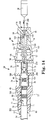
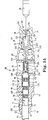
- Figures 13-15 are several cross-sectional views showing an illustrative method of using the implant tool 34 to implant and test a lead 12 within the body.
- the implanting physician may remove the implantable lead 12, implant tool 34, and stylet 36 from the device packaging, and push the terminal end 40 of the lead 12 into the opening 62 of the main body 58 while also pinching the levers 72 together.
- the distance at which the terminal end 40 is inserted through the opening 62 can be gauged using the slot 68 and indicator arrows 70.
- the physician releases the levers 72, causing the distal section 60 of the main body 58 to crimp onto the proximal-most portion 71 of the lead terminal boot 54.
- the electrical spring contact clips 78,80 are configured to expand outwardly to their equilibrium positions shown in Figures 11-12 , creating a small gap or spacing between the internal ridges 172,192 and the pin and ring contacts 44,46.
- An interior lumen 196 of the main body 58 is also sized to form a gap around at least a portion of the terminal end 40 of the implantable lead 12. In some embodiments, and as further shown in Figures 13-15 , the inner diameter of the interior lumen 196 gradually decreases in size along its length towards the proximal section 64 of the main body 58.
- a wall 198 forming part of the main body 58 separates the openings 74,76 from each other, and is configured to contact a proximal section 200 of the implantable lead 12, as shown. Due to the size and shape of the interior lumen 196, the terminal end 40 of the implantable lead 12 is supported at only sections 200 and 202 such that the terminal pin 44 and ring contacts 46,48,50 do not contact the main body 58 of the implant tool 34.
- the fixation knob 90 is pulled in a proximal direction, causing the collet 92 to disengage from the terminal pin 44.
- the proximal-most end 204 of the terminal pin 44 is located within only the distal opening 146. This aligns the collet 92 to the terminal pin 44 such that the pin 44 is held in position within the interior lumen 196 of the main body 58, but does not move in response to rotation of the knob 90.
- the implanting physician pushes the knob 90 distally towards the main body 58 in the direction indicated generally by arrow 206. Movement of the knob 90 towards the main body 58 causes the terminal pin 44 to enter the sleeve 144 within the collet 92. When this occurs, the sleeve 144 and clutch mechanism 108 are configured to frictionally engage the terminal pin 44.
- the implanting physician may then rotate the knob 90 in a counterclockwise direction to retract the fixation helix 20 from the implanting lead 12. In some embodiments, rotation of the knob 90 can be done manually, using the physicians fingers.
- a separate device such as a wrench could be used to rotate the knob 90 and engage the fixation helix 20.
- a wrench could be attached to a knob with an arm, finger hole, keyway, or other such feature.
- the device comprises a molded part made from a soft polymeric material that stretches over the tip of the knob 90 and uses the crown 95 as a spline to turn the knob 90 and engage the fixation helix 20.
- the implanting physician can count the number of knob turns using the counting nub 96 on the knob 90.
- the clutch mechanism 108 prevents the terminal pin 44 from recoiling or slipping during each successive turn of the knob 90.
- the implant tool 34 is configured to produce a clicking sound during each rotation cycle, providing the physician with audible feedback that the fixation helix 20 is being rotated.
- the fixation helix 20 is extended into heart tissue by rotating the terminal pin 44 via the knob 90.
- the terminal pin 44 is coupled to a driveshaft or a coil conductor serving as a driveshaft.
- the torque is typically applied in a clockwise direction in order to deploy the fixation helix 20 within the heart tissue. After helix deployment, it is often desirable to release the excess clockwise torque. If the excess torque is not released, then this may lead to an increase in turncount, leading the implanting physician to improperly conclude that the mechanism is malfunctioning.
- the implanting physician pulls the knob 90 proximally back to the disengaged position shown in Figure 13 , causing the terminal pin 44 to disengage from within the sleeve 144 of the collet 92. This can be done, for example, after every application of a clockwise or counterclockwise torque in order to ensure consistent helix extension-retraction performance.
- the terminal pin 44 is free to rotate within the interior lumen 196 of the main body 58, relieving any torque imparted to the implantable lead 12 during engagement of the fixation helix 20 into the heart tissue. Once this torque is relieved, the implanting physician can then push the knob 90 distally back to the engaged position shown in Figure 14 .
- the implanting physician connects the alligator clips 86,88 to the electrical spring contact clips 78,80, as shown, for example, in Figure 5 .
- the inwardly-directed spring force of the alligator clips 86,88 causes the ends 176,178,154,156 of the electrical spring contact clips 78,80 to move toward each other which, in turn, causes the interior ridges 172,192 on the clips 78,80 to contact the corresponding terminal contact 44,46.
- the implanting physician may then adjust the positioning of the implantable lead 12 and/or the fixation helix 20, as discussed above. Once this process is complete, the implanting physician can then remove the alligator clips 86,88 and stylet 36 from the implant tool 34. The implant tool 34 can then be removed from the implantable lead 12 by engaging the release levers 72 and pulling the terminal end 40 out through the opening 62. The terminal end 40 of the implantable lead 12 can then be connected to another device implanted within the body.
Landscapes
- Health & Medical Sciences (AREA)
- Cardiology (AREA)
- Heart & Thoracic Surgery (AREA)
- Engineering & Computer Science (AREA)
- Biomedical Technology (AREA)
- Nuclear Medicine, Radiotherapy & Molecular Imaging (AREA)
- Radiology & Medical Imaging (AREA)
- Life Sciences & Earth Sciences (AREA)
- Animal Behavior & Ethology (AREA)
- General Health & Medical Sciences (AREA)
- Public Health (AREA)
- Veterinary Medicine (AREA)
- Electrotherapy Devices (AREA)
Claims (14)
- Outil d'implant (34) destiné à être utilisé avec une sonde/dérivation implantable (12), l'outil d'implant comprenant :un corps principal (58) qui comporte une section de serrage distale (60), une section proximale (64) et une lumière intérieure, la section de serrage distale incluant une ouverture (62) qui est adaptée de manière à ce qu'elle reçoive par friction une gaine terminale (54) de la dérivation implantable ;une pluralité d'éléments de contact à ressort(s) qui sont couplés au corps principal ; etun mécanisme à bouton rotatif (66) qui est couplé au corps principal, le mécanisme à bouton rotatif pouvant être actionné entre une première position qui est configurée de manière à réaliser un engagement par friction et de manière à faire tourner une broche terminale (44) de la dérivation implantable et une seconde position qui est configurée de manière à désengager l'outil d'implant vis-à-vis de la broche terminale afin de faciliter une libération de couple ;caractérisé en ce que le mécanisme à bouton rotatif (66) inclut un bouton (90) et une douille/un collet (92) qui, en association, sont configurés de manière à ce qu'ils engagent à rotation la broche terminale afin d'actionner et de déployer une hélice de fixation de la dérivation implantable (12) en faisant tourner seulement le bouton (90) sans faire tourner l'outil d'implant complet (34) tandis que la dérivation implantable (12) est maintenue stationnaire à l'intérieur du corps principal (58) de l'outil d'implant (34).
- Outil d'implant selon la revendication 1, dans lequel le corps principal inclut en outre un certain nombre de leviers (72) qui sont configurés de manière à ce qu'ils permettent de régler la taille/dimension de l'ouverture pour créer un ajustement par friction entre le corps principal et l'extrémité terminale de la dérivation implantable.
- Outil d'implant selon la revendication 1, dans lequel la section de serrage distale du corps principal inclut une fente (68) et un certain nombre de flèches indicatrices (70) pour confirmer le positionnement de la gaine terminale à l'intérieur de l'outil d'implant.
- Outil d'implant selon la revendication 1, dans lequel le bouton (90) inclut une ouverture en forme d'entonnoir (126) qui est configurée de manière à ce qu'elle reçoive un élément de renforcement/raidissement.
- Outil d'implant selon la revendication 4, dans lequel l'ouverture de bouton (126) inclut une lame de nettoyage (128) et un dispositif de lubrification.
- Outil d'implant selon la revendication 1, dans lequel le collet (92) inclut un corps de collet (98) qui comporte une première section (100) qui est fixée fermement à une partie intérieure du bouton et une seconde section (102) qui est configurée de manière à ce qu'elle engage un mécanisme d'embrayage (108) du corps principal.
- Outil d'implant selon la revendication 6, dans lequel le corps de collet (98) inclut un manchon de préhension (144) qui est configuré de manière à ce qu'il reçoive par friction la broche terminale dans ladite première position.
- Outil d'implant selon la revendication 6, dans lequel le corps de collet (98) inclut une ouverture distale évasée (146) qui est configurée de manière à ce qu'elle reçoive une extrémité proximale de la broche terminale dans ladite seconde position.
- Outil d'implant selon la revendication 6, dans lequel le mécanisme à bouton (66) inclut en outre un mécanisme à autofreinage/freinage automatique qui est configuré de manière à ce qu'il élimine un recul du bouton pendant la rotation du mécanisme à bouton.
- Outil d'implant selon la revendication 1, dans lequel chaque élément de contact à ressort(s) inclut un moyen d'agrafage/clip (78, 80) qui comporte une surface orientée vers l'extérieur (160, 182) qui est configurée de manière à ce qu'elle reçoive un connecteur électrique et une surface orientée vers l'intérieur (158, 180) qui est configurée de manière à ce qu'elle engage un contact électrique sur l'extrémité terminale de la dérivation implantable.
- Outil d'implant selon la revendication 1, dans lequel les éléments de contact à ressort(s) de la pluralité d'éléments de contact à ressort(s) sont alignés latéralement les uns par rapport aux autres suivant une longueur de l'outil d'implant.
- Outil d'implant selon la revendication 1, dans lequel les éléments de contact à ressort(s) de la pluralité d'éléments de contact à ressort(s) incluent :un premier moyen d'agrafage/clip de contact à ressort(s) (78) qui est configuré de manière à ce qu'il engage la broche terminale de la dérivation implantable ; etun second moyen d'agrafage/clip de contact à ressort(s) (80) qui est configuré de manière à ce qu'il engage un contact annulaire (46) de la dérivation implantable.
- Outil d'implant selon la revendication 12, comprenant en outre au moins un moyen d'agrafage/clip de contact à ressort(s) additionnel qui est configuré de manière à ce qu'il engage un contact de la dérivation implantable.
- Système (10) pour implanter et tester une dérivation implantable à l'intérieur du corps d'un patient, le système comprenant :une dérivation implantable (12) ; etun outil d'implant (34) qui comprend :un corps principal (58) qui comporte une section de serrage distale (60), une section proximale (64) et une lumière intérieure, la section de serrage distale incluant une ouverture (62) qui est adaptée de manière à ce qu'elle reçoive par friction une gaine (54) de la dérivation implantable ;une pluralité d'éléments de contact à ressort(s) qui sont couplés au corps principal ; etun mécanisme à bouton rotatif (66) qui est couplé au corps principal, le mécanisme à bouton rotatif pouvant être actionné entre une première position qui est configurée de manière à réaliser un engagement par friction et de manière à faire tourner une broche terminale (44) de la dérivation implantable et une seconde position qui est configurée de manière à réaliser un désengagement vis-à-vis de la broche terminale ;caractérisé en ce que le mécanisme à bouton (66) inclut un bouton (90) et une douille/un collet (92) qui, en association, sont configurés de manière à ce qu'ils engagent à rotation la broche terminale afin d'actionner et de déployer une hélice de fixation de la dérivation implantable (12) en faisant tourner seulement le bouton (90) sans faire tourner l'outil d'implant complet (34) tandis que la dérivation implantable (12) est maintenue stationnaire à l'intérieur du corps principal (58) de l'outil d'implant (34).
Applications Claiming Priority (3)
| Application Number | Priority Date | Filing Date | Title |
|---|---|---|---|
| US29116309P | 2009-12-30 | 2009-12-30 | |
| US12/976,562 US9302092B2 (en) | 2009-12-30 | 2010-12-22 | Multi-function lead implant tool |
| PCT/US2010/062215 WO2011082160A2 (fr) | 2009-12-30 | 2010-12-28 | Outil d'implant de fils multifonction |
Publications (2)
| Publication Number | Publication Date |
|---|---|
| EP2519310A2 EP2519310A2 (fr) | 2012-11-07 |
| EP2519310B1 true EP2519310B1 (fr) | 2018-07-04 |
Family
ID=44188454
Family Applications (1)
| Application Number | Title | Priority Date | Filing Date |
|---|---|---|---|
| EP10812830.7A Active EP2519310B1 (fr) | 2009-12-30 | 2010-12-28 | Outil d'implant de fils multifonction |
Country Status (4)
| Country | Link |
|---|---|
| US (1) | US9302092B2 (fr) |
| EP (1) | EP2519310B1 (fr) |
| JP (1) | JP5461703B2 (fr) |
| WO (1) | WO2011082160A2 (fr) |
Cited By (1)
| Publication number | Priority date | Publication date | Assignee | Title |
|---|---|---|---|---|
| EP4667045A1 (fr) | 2024-06-18 | 2025-12-24 | ODU GmbH & Co KG. | Connecteur pour connecter électriquement un dispositif de connexion implantable |
Families Citing this family (29)
| Publication number | Priority date | Publication date | Assignee | Title |
|---|---|---|---|---|
| US9083129B2 (en) | 2010-07-14 | 2015-07-14 | Cardiac Pacemakers, Inc. | Multipolar lead evaluation device |
| US8958878B2 (en) | 2010-09-17 | 2015-02-17 | Michael Cejnar | Low profile adapter for continuous connection of pacemaker lead during implantation |
| JP2013542833A (ja) * | 2010-11-19 | 2013-11-28 | カーディアック ペースメイカーズ, インコーポレイテッド | 多機能型リード線移植用具 |
| US8666514B2 (en) | 2010-11-19 | 2014-03-04 | Cardiac Pacemakers, Inc. | Peel-away IS-4/DF-4 lead implant tool with electrical contacts |
| WO2012087385A1 (fr) | 2010-12-21 | 2012-06-28 | Cardiac Pacemakers, Inc. | Adaptateur de dérivation pour essayer des seuils de è stimulation à travers de multiples vecteurs au niveau d'implant |
| EP2866874B1 (fr) * | 2012-06-28 | 2019-01-02 | Volcano Corporation | Connecteurs de charge latérale destinés à être utilisés avec des dispositifs intravasculaires et systèmes et procédés associés |
| EP3539612B1 (fr) | 2012-07-26 | 2024-09-04 | Nyxoah SA | Encapsulation d'implant |
| US10052097B2 (en) | 2012-07-26 | 2018-08-21 | Nyxoah SA | Implant unit delivery tool |
| DE102013001021B4 (de) | 2013-01-22 | 2015-05-13 | Osypka Ag | Externer Herzschrittmacher mit einer über einen Steckverbinder angeschlossenen, temporär mit einem Herzen verbindbaren Elektrode |
| US9949739B2 (en) | 2013-02-27 | 2018-04-24 | Microvention, Inc. | Integral wiping system and method |
| WO2014144143A1 (fr) | 2013-03-15 | 2014-09-18 | Hni Technologies Inc. | Chaise ayant une flexion arrière activée |
| KR20160100900A (ko) * | 2013-06-17 | 2016-08-24 | 아디 매쉬아취 | 임플란트 유닛 이송 도구 |
| US10195423B2 (en) * | 2016-01-19 | 2019-02-05 | Axonics Modulation Technologies, Inc. | Multichannel clip device and methods of use |
| WO2019050438A1 (fr) * | 2017-09-11 | 2019-03-14 | Александр Николаевич АЛЕКСАНДРОВ | Adaptateur de stimulateur cardiaque désimplanté pour électrostimulation cardiaque temporaire |
| RU193619U1 (ru) * | 2017-09-11 | 2019-11-07 | Александр Николаевич Александров | Переходник к постоянному кардиостимулятору для временной электрокардиостимуляции |
| WO2019148201A1 (fr) | 2018-01-29 | 2019-08-01 | Bard Access Systems, Inc. | Système de connexion pour établir une connexion électrique à travers un champ et méthodes associées |
| CN112135577B (zh) | 2018-05-18 | 2024-10-15 | 巴德阿克塞斯系统股份有限公司 | 用于建立通过盖布的电连接的连接系统及其方法 |
| US12114863B2 (en) | 2018-12-05 | 2024-10-15 | Microvention, Inc. | Implant delivery system |
| US11272956B2 (en) | 2019-03-17 | 2022-03-15 | Ripple, LLC | Systems and methods for implanting electrode leads |
| US11737848B2 (en) | 2019-07-29 | 2023-08-29 | Bard Access Systems, Inc. | Connection systems and methods for establishing optical and electrical connections through a drape |
| CA3150924A1 (fr) | 2019-08-08 | 2021-02-11 | Bard Access Systems, Inc. | Modules de connecteur de fibres optiques comprenant des systemes de detection de forme et procedes associes |
| CN111404103B (zh) * | 2019-11-26 | 2021-10-08 | 国网浙江省电力有限公司金华供电公司 | 一种输电线路直流融冰短接夹头 |
| US11944828B2 (en) | 2020-09-24 | 2024-04-02 | Medtronic, Inc. | Rotatable adapter for connecting implantable medical leads to test devices |
| US12596232B2 (en) | 2020-10-28 | 2026-04-07 | Bard Access Systems, Inc. | Systems and methods including procedural barrier-breaching connectors and connection-establishing devices |
| US11813468B2 (en) * | 2021-07-16 | 2023-11-14 | Medtronic, Inc. | Connector conditioning/bore plug |
| US20240366951A1 (en) * | 2021-07-23 | 2024-11-07 | Universitair Ziekenhuis Antwerpen | Tool for continuous insertion-depth monitoring for implantable lead |
| US20230347142A1 (en) * | 2022-04-27 | 2023-11-02 | Pacesetter, Inc. | Pacing lead conversion tool |
| EP4514448A1 (fr) * | 2022-04-27 | 2025-03-05 | Pacesetter, Inc. | Outil de conversion de sonde de stimulation |
| WO2024157102A1 (fr) * | 2023-01-26 | 2024-08-02 | Medtronic, Inc. | Système de connecteur conducteur externe |
Family Cites Families (29)
| Publication number | Priority date | Publication date | Assignee | Title |
|---|---|---|---|---|
| US4027678A (en) * | 1975-11-19 | 1977-06-07 | Vitatron Medical B.V. | Pacing system with connector for connecting electrode to pacer |
| US4278093A (en) * | 1976-06-08 | 1981-07-14 | American Technology, Inc. | Interchangeable pacemaker connector for leads |
| US4209019A (en) * | 1979-01-05 | 1980-06-24 | Medtronic, Inc. | Stylet insertion guide and rotation control device for use with body implantable lead |
| US4744371A (en) * | 1987-04-27 | 1988-05-17 | Cordis Leads, Inc. | Multi-conductor lead assembly for temporary use |
| US5275620A (en) * | 1990-05-21 | 1994-01-04 | Telectronics, N.V. | Implantable lead connectors and remote lead assembly |
| US5557210A (en) * | 1992-11-20 | 1996-09-17 | Pacesetter, Inc. | Universal cable connector for temporarily connecting implantable stimulation leads and implantable stimulation devices with a non-implantable system analyzer |
| US5334045A (en) * | 1992-11-20 | 1994-08-02 | Siemens Pacesetter, Inc. | Universal cable connector for temporarily connecting implantable leads and implantable medical devices with a non-implantable system analyzer |
| US5354326A (en) * | 1993-01-27 | 1994-10-11 | Medtronic, Inc. | Screening cable connector for interface to implanted lead |
| US5782841A (en) * | 1993-08-10 | 1998-07-21 | Medtronic, Inc. | Tunneling tool for subcutaneous lead placement |
| SE511728C2 (sv) * | 1994-01-27 | 1999-11-15 | Nilsson Ingvar | Anordning för detektering av slitage hos en SNCR-lans |
| US5931861A (en) * | 1997-04-25 | 1999-08-03 | Medtronic, Inc. | Medical lead adaptor having rotatable locking clip mechanism |
| US5782892A (en) * | 1997-04-25 | 1998-07-21 | Medtronic, Inc. | Medical lead adaptor for external medical device |
| US6463334B1 (en) * | 1998-11-02 | 2002-10-08 | Cardiac Pacemakers, Inc. | Extendable and retractable lead |
| US6129751A (en) * | 1998-07-28 | 2000-10-10 | Intermedics Inc. | Cardiac lead with active fixation and biocompatible lubricant |
| US6162101A (en) * | 1998-09-03 | 2000-12-19 | Pmt Corporation | Connector assembly for electrodes |
| SE9804138D0 (sv) * | 1998-11-30 | 1998-11-30 | Pacesetter Ab | Device in connection with pacers |
| US6154678A (en) | 1999-03-19 | 2000-11-28 | Advanced Neuromodulation Systems, Inc. | Stimulation lead connector |
| US6415168B1 (en) * | 2000-04-19 | 2002-07-02 | Ad-Tech Medical Instrument Corporation | Electrical connector for multi-contact medical electrodes |
| US6580948B2 (en) * | 2000-04-25 | 2003-06-17 | Medtronic, Inc. | Interface devices for instruments in communication with implantable medical devices |
| US6968235B2 (en) * | 2001-07-17 | 2005-11-22 | Medtronic, Inc. | Enhanced method and apparatus to identify and connect a small diameter lead with a low profile lead connector |
| US6659611B2 (en) * | 2001-12-28 | 2003-12-09 | International Business Machines Corporation | System and method for eye gaze tracking using corneal image mapping |
| US7110827B2 (en) * | 2003-04-25 | 2006-09-19 | Medtronic, Inc. | Electrical connectors for medical lead having weld-less wiring connection |
| US7130699B2 (en) * | 2003-05-13 | 2006-10-31 | Medtronic, Inc. | Medical lead adaptor assembly |
| US20050177199A1 (en) * | 2004-02-09 | 2005-08-11 | Cardiac Pacemakers, Inc. | PSA cable and connector for quadripolar lead terminal |
| WO2005082451A1 (fr) * | 2004-02-23 | 2005-09-09 | Synovis Life Technologies, Inc. | Connecteurs d'essai pour fils implantables et procedes associes |
| US7753696B2 (en) * | 2005-05-12 | 2010-07-13 | Cardiac Pacemakers, Inc. | Lead terminal multi-tool |
| EP2004288B1 (fr) * | 2006-03-23 | 2010-10-20 | Medtronic, Inc. | Systemes de connexion de fils electriques medicaux et leur procede de fabrication |
| US8571682B2 (en) * | 2007-04-11 | 2013-10-29 | Cardiac Pacemakers, Inc. | Connecting apparatus and methods |
| US8038628B2 (en) * | 2007-05-24 | 2011-10-18 | Radi Medical Systems Ab | Torque device for a sensor guide wire |
-
2010
- 2010-12-22 US US12/976,562 patent/US9302092B2/en active Active
- 2010-12-28 WO PCT/US2010/062215 patent/WO2011082160A2/fr not_active Ceased
- 2010-12-28 EP EP10812830.7A patent/EP2519310B1/fr active Active
- 2010-12-28 JP JP2012537246A patent/JP5461703B2/ja not_active Expired - Fee Related
Non-Patent Citations (1)
| Title |
|---|
| None * |
Cited By (2)
| Publication number | Priority date | Publication date | Assignee | Title |
|---|---|---|---|---|
| EP4667045A1 (fr) | 2024-06-18 | 2025-12-24 | ODU GmbH & Co KG. | Connecteur pour connecter électriquement un dispositif de connexion implantable |
| EP4667046A1 (fr) | 2024-06-18 | 2025-12-24 | ODU GmbH & Co KG. | Connecteur pour connecter électriquement un dispositif de connexion implantable |
Also Published As
| Publication number | Publication date |
|---|---|
| EP2519310A2 (fr) | 2012-11-07 |
| US9302092B2 (en) | 2016-04-05 |
| WO2011082160A2 (fr) | 2011-07-07 |
| US20110160824A1 (en) | 2011-06-30 |
| WO2011082160A3 (fr) | 2012-03-15 |
| JP2013508122A (ja) | 2013-03-07 |
| JP5461703B2 (ja) | 2014-04-02 |
Similar Documents
| Publication | Publication Date | Title |
|---|---|---|
| EP2519310B1 (fr) | Outil d'implant de fils multifonction | |
| US20120130397A1 (en) | Multi-function lead implant tool | |
| US9744350B2 (en) | Method for the implantation of active fixation medical leads | |
| US8903513B2 (en) | Apparatus and system for implanting an autonomous intracardiac capsule | |
| US20100305670A1 (en) | Method and Devices for Coupling a Lead Conductor Member to a Functional Component | |
| EP2424613B1 (fr) | Fil électrique implantable | |
| US8958878B2 (en) | Low profile adapter for continuous connection of pacemaker lead during implantation | |
| JPH10512466A (ja) | 自然復帰する収縮可能な取り付け装置を有する埋め込み可能な心臓内導線 | |
| EP2379164A1 (fr) | Dérivation implantable médicale et procédé garantissant sa fixation correcte et sûre à un organe | |
| US11376420B2 (en) | Terminal tool for continuous electrical monitoring during lead implant | |
| EP4233995A2 (fr) | Ensembles d'attache pour systèmes de distribution de dispositifs médicaux | |
| US11464987B2 (en) | Implantable medical device and delivery catheter apparatus system and method | |
| CN116920279A (zh) | 一种用于起搏的导线 | |
| EP4252830A1 (fr) | Stimulateur cardiaque sans fil et élément d'extrémité de tête et élément d'extrémité de queue de ce dernier | |
| EP4370199B1 (fr) | Ensembles attaches pour systèmes de récupération de dispositif médical | |
| US20080208306A1 (en) | Implantable medical lead with reversible fixation mechanism | |
| EP4486433B1 (fr) | Système d'extraction de sonde pour connecteurs de sonde retenus | |
| EP4556058A1 (fr) | Biostimulateur ayant une électrode de stimulation s'étendant latéralement | |
| EP4516348B1 (fr) | Biostimulateur modulaire | |
| WO2025038317A1 (fr) | Système de transport de biostimulateur à mécanisme de préhension |
Legal Events
| Date | Code | Title | Description |
|---|---|---|---|
| PUAI | Public reference made under article 153(3) epc to a published international application that has entered the european phase |
Free format text: ORIGINAL CODE: 0009012 |
|
| 17P | Request for examination filed |
Effective date: 20120516 |
|
| AK | Designated contracting states |
Kind code of ref document: A2 Designated state(s): AL AT BE BG CH CY CZ DE DK EE ES FI FR GB GR HR HU IE IS IT LI LT LU LV MC MK MT NL NO PL PT RO RS SE SI SK SM TR |
|
| DAX | Request for extension of the european patent (deleted) | ||
| GRAP | Despatch of communication of intention to grant a patent |
Free format text: ORIGINAL CODE: EPIDOSNIGR1 |
|
| INTG | Intention to grant announced |
Effective date: 20180131 |
|
| RIN1 | Information on inventor provided before grant (corrected) |
Inventor name: HALVORSON, ROBBIE Inventor name: REDDY, G. SHANTANU Inventor name: WOODCOX, BRADLEY Inventor name: WARE, ERIC A. |
|
| GRAS | Grant fee paid |
Free format text: ORIGINAL CODE: EPIDOSNIGR3 |
|
| GRAA | (expected) grant |
Free format text: ORIGINAL CODE: 0009210 |
|
| AK | Designated contracting states |
Kind code of ref document: B1 Designated state(s): AL AT BE BG CH CY CZ DE DK EE ES FI FR GB GR HR HU IE IS IT LI LT LU LV MC MK MT NL NO PL PT RO RS SE SI SK SM TR |
|
| REG | Reference to a national code |
Ref country code: GB Ref legal event code: FG4D |
|
| REG | Reference to a national code |
Ref country code: CH Ref legal event code: EP |
|
| REG | Reference to a national code |
Ref country code: AT Ref legal event code: REF Ref document number: 1013837 Country of ref document: AT Kind code of ref document: T Effective date: 20180715 |
|
| REG | Reference to a national code |
Ref country code: IE Ref legal event code: FG4D |
|
| REG | Reference to a national code |
Ref country code: DE Ref legal event code: R096 Ref document number: 602010051706 Country of ref document: DE |
|
| REG | Reference to a national code |
Ref country code: NL Ref legal event code: FP |
|
| REG | Reference to a national code |
Ref country code: LT Ref legal event code: MG4D |
|
| REG | Reference to a national code |
Ref country code: AT Ref legal event code: MK05 Ref document number: 1013837 Country of ref document: AT Kind code of ref document: T Effective date: 20180704 |
|
| PG25 | Lapsed in a contracting state [announced via postgrant information from national office to epo] |
Ref country code: IS Free format text: LAPSE BECAUSE OF FAILURE TO SUBMIT A TRANSLATION OF THE DESCRIPTION OR TO PAY THE FEE WITHIN THE PRESCRIBED TIME-LIMIT Effective date: 20181104 Ref country code: AT Free format text: LAPSE BECAUSE OF FAILURE TO SUBMIT A TRANSLATION OF THE DESCRIPTION OR TO PAY THE FEE WITHIN THE PRESCRIBED TIME-LIMIT Effective date: 20180704 Ref country code: NO Free format text: LAPSE BECAUSE OF FAILURE TO SUBMIT A TRANSLATION OF THE DESCRIPTION OR TO PAY THE FEE WITHIN THE PRESCRIBED TIME-LIMIT Effective date: 20181004 Ref country code: GR Free format text: LAPSE BECAUSE OF FAILURE TO SUBMIT A TRANSLATION OF THE DESCRIPTION OR TO PAY THE FEE WITHIN THE PRESCRIBED TIME-LIMIT Effective date: 20181005 Ref country code: FI Free format text: LAPSE BECAUSE OF FAILURE TO SUBMIT A TRANSLATION OF THE DESCRIPTION OR TO PAY THE FEE WITHIN THE PRESCRIBED TIME-LIMIT Effective date: 20180704 Ref country code: LT Free format text: LAPSE BECAUSE OF FAILURE TO SUBMIT A TRANSLATION OF THE DESCRIPTION OR TO PAY THE FEE WITHIN THE PRESCRIBED TIME-LIMIT Effective date: 20180704 Ref country code: BG Free format text: LAPSE BECAUSE OF FAILURE TO SUBMIT A TRANSLATION OF THE DESCRIPTION OR TO PAY THE FEE WITHIN THE PRESCRIBED TIME-LIMIT Effective date: 20181004 Ref country code: RS Free format text: LAPSE BECAUSE OF FAILURE TO SUBMIT A TRANSLATION OF THE DESCRIPTION OR TO PAY THE FEE WITHIN THE PRESCRIBED TIME-LIMIT Effective date: 20180704 Ref country code: SE Free format text: LAPSE BECAUSE OF FAILURE TO SUBMIT A TRANSLATION OF THE DESCRIPTION OR TO PAY THE FEE WITHIN THE PRESCRIBED TIME-LIMIT Effective date: 20180704 Ref country code: PL Free format text: LAPSE BECAUSE OF FAILURE TO SUBMIT A TRANSLATION OF THE DESCRIPTION OR TO PAY THE FEE WITHIN THE PRESCRIBED TIME-LIMIT Effective date: 20180704 Ref country code: CZ Free format text: LAPSE BECAUSE OF FAILURE TO SUBMIT A TRANSLATION OF THE DESCRIPTION OR TO PAY THE FEE WITHIN THE PRESCRIBED TIME-LIMIT Effective date: 20180704 |
|
| PG25 | Lapsed in a contracting state [announced via postgrant information from national office to epo] |
Ref country code: AL Free format text: LAPSE BECAUSE OF FAILURE TO SUBMIT A TRANSLATION OF THE DESCRIPTION OR TO PAY THE FEE WITHIN THE PRESCRIBED TIME-LIMIT Effective date: 20180704 Ref country code: HR Free format text: LAPSE BECAUSE OF FAILURE TO SUBMIT A TRANSLATION OF THE DESCRIPTION OR TO PAY THE FEE WITHIN THE PRESCRIBED TIME-LIMIT Effective date: 20180704 Ref country code: LV Free format text: LAPSE BECAUSE OF FAILURE TO SUBMIT A TRANSLATION OF THE DESCRIPTION OR TO PAY THE FEE WITHIN THE PRESCRIBED TIME-LIMIT Effective date: 20180704 Ref country code: ES Free format text: LAPSE BECAUSE OF FAILURE TO SUBMIT A TRANSLATION OF THE DESCRIPTION OR TO PAY THE FEE WITHIN THE PRESCRIBED TIME-LIMIT Effective date: 20180704 |
|
| REG | Reference to a national code |
Ref country code: DE Ref legal event code: R097 Ref document number: 602010051706 Country of ref document: DE |
|
| PG25 | Lapsed in a contracting state [announced via postgrant information from national office to epo] |
Ref country code: RO Free format text: LAPSE BECAUSE OF FAILURE TO SUBMIT A TRANSLATION OF THE DESCRIPTION OR TO PAY THE FEE WITHIN THE PRESCRIBED TIME-LIMIT Effective date: 20180704 Ref country code: EE Free format text: LAPSE BECAUSE OF FAILURE TO SUBMIT A TRANSLATION OF THE DESCRIPTION OR TO PAY THE FEE WITHIN THE PRESCRIBED TIME-LIMIT Effective date: 20180704 |
|
| PLBE | No opposition filed within time limit |
Free format text: ORIGINAL CODE: 0009261 |
|
| STAA | Information on the status of an ep patent application or granted ep patent |
Free format text: STATUS: NO OPPOSITION FILED WITHIN TIME LIMIT |
|
| PG25 | Lapsed in a contracting state [announced via postgrant information from national office to epo] |
Ref country code: SK Free format text: LAPSE BECAUSE OF FAILURE TO SUBMIT A TRANSLATION OF THE DESCRIPTION OR TO PAY THE FEE WITHIN THE PRESCRIBED TIME-LIMIT Effective date: 20180704 Ref country code: DK Free format text: LAPSE BECAUSE OF FAILURE TO SUBMIT A TRANSLATION OF THE DESCRIPTION OR TO PAY THE FEE WITHIN THE PRESCRIBED TIME-LIMIT Effective date: 20180704 Ref country code: SM Free format text: LAPSE BECAUSE OF FAILURE TO SUBMIT A TRANSLATION OF THE DESCRIPTION OR TO PAY THE FEE WITHIN THE PRESCRIBED TIME-LIMIT Effective date: 20180704 |
|
| 26N | No opposition filed |
Effective date: 20190405 |
|
| REG | Reference to a national code |
Ref country code: CH Ref legal event code: PL |
|
| PG25 | Lapsed in a contracting state [announced via postgrant information from national office to epo] |
Ref country code: MC Free format text: LAPSE BECAUSE OF FAILURE TO SUBMIT A TRANSLATION OF THE DESCRIPTION OR TO PAY THE FEE WITHIN THE PRESCRIBED TIME-LIMIT Effective date: 20180704 Ref country code: SI Free format text: LAPSE BECAUSE OF FAILURE TO SUBMIT A TRANSLATION OF THE DESCRIPTION OR TO PAY THE FEE WITHIN THE PRESCRIBED TIME-LIMIT Effective date: 20180704 Ref country code: LU Free format text: LAPSE BECAUSE OF NON-PAYMENT OF DUE FEES Effective date: 20181228 |
|
| REG | Reference to a national code |
Ref country code: IE Ref legal event code: MM4A |
|
| REG | Reference to a national code |
Ref country code: BE Ref legal event code: MM Effective date: 20181231 |
|
| PG25 | Lapsed in a contracting state [announced via postgrant information from national office to epo] |
Ref country code: IE Free format text: LAPSE BECAUSE OF NON-PAYMENT OF DUE FEES Effective date: 20181228 |
|
| PG25 | Lapsed in a contracting state [announced via postgrant information from national office to epo] |
Ref country code: BE Free format text: LAPSE BECAUSE OF NON-PAYMENT OF DUE FEES Effective date: 20181231 |
|
| PG25 | Lapsed in a contracting state [announced via postgrant information from national office to epo] |
Ref country code: LI Free format text: LAPSE BECAUSE OF NON-PAYMENT OF DUE FEES Effective date: 20181231 Ref country code: CH Free format text: LAPSE BECAUSE OF NON-PAYMENT OF DUE FEES Effective date: 20181231 |
|
| PG25 | Lapsed in a contracting state [announced via postgrant information from national office to epo] |
Ref country code: MT Free format text: LAPSE BECAUSE OF NON-PAYMENT OF DUE FEES Effective date: 20181228 |
|
| PGFP | Annual fee paid to national office [announced via postgrant information from national office to epo] |
Ref country code: NL Payment date: 20191212 Year of fee payment: 10 |
|
| PGFP | Annual fee paid to national office [announced via postgrant information from national office to epo] |
Ref country code: IT Payment date: 20191209 Year of fee payment: 10 Ref country code: FR Payment date: 20191114 Year of fee payment: 10 |
|
| PG25 | Lapsed in a contracting state [announced via postgrant information from national office to epo] |
Ref country code: TR Free format text: LAPSE BECAUSE OF FAILURE TO SUBMIT A TRANSLATION OF THE DESCRIPTION OR TO PAY THE FEE WITHIN THE PRESCRIBED TIME-LIMIT Effective date: 20180704 |
|
| PG25 | Lapsed in a contracting state [announced via postgrant information from national office to epo] |
Ref country code: PT Free format text: LAPSE BECAUSE OF FAILURE TO SUBMIT A TRANSLATION OF THE DESCRIPTION OR TO PAY THE FEE WITHIN THE PRESCRIBED TIME-LIMIT Effective date: 20180704 |
|
| PG25 | Lapsed in a contracting state [announced via postgrant information from national office to epo] |
Ref country code: HU Free format text: LAPSE BECAUSE OF FAILURE TO SUBMIT A TRANSLATION OF THE DESCRIPTION OR TO PAY THE FEE WITHIN THE PRESCRIBED TIME-LIMIT; INVALID AB INITIO Effective date: 20101228 Ref country code: CY Free format text: LAPSE BECAUSE OF FAILURE TO SUBMIT A TRANSLATION OF THE DESCRIPTION OR TO PAY THE FEE WITHIN THE PRESCRIBED TIME-LIMIT Effective date: 20180704 Ref country code: MK Free format text: LAPSE BECAUSE OF NON-PAYMENT OF DUE FEES Effective date: 20180704 |
|
| REG | Reference to a national code |
Ref country code: NL Ref legal event code: MM Effective date: 20210101 |
|
| PG25 | Lapsed in a contracting state [announced via postgrant information from national office to epo] |
Ref country code: NL Free format text: LAPSE BECAUSE OF NON-PAYMENT OF DUE FEES Effective date: 20210101 |
|
| PG25 | Lapsed in a contracting state [announced via postgrant information from national office to epo] |
Ref country code: FR Free format text: LAPSE BECAUSE OF NON-PAYMENT OF DUE FEES Effective date: 20201231 Ref country code: IT Free format text: LAPSE BECAUSE OF NON-PAYMENT OF DUE FEES Effective date: 20201228 |
|
| PGFP | Annual fee paid to national office [announced via postgrant information from national office to epo] |
Ref country code: DE Payment date: 20251126 Year of fee payment: 16 |
|
| PGFP | Annual fee paid to national office [announced via postgrant information from national office to epo] |
Ref country code: GB Payment date: 20251120 Year of fee payment: 16 |