EP2519659B1 - Barrière thermique ceramique nano- et microstructurée - Google Patents
Barrière thermique ceramique nano- et microstructurée Download PDFInfo
- Publication number
- EP2519659B1 EP2519659B1 EP20100798799 EP10798799A EP2519659B1 EP 2519659 B1 EP2519659 B1 EP 2519659B1 EP 20100798799 EP20100798799 EP 20100798799 EP 10798799 A EP10798799 A EP 10798799A EP 2519659 B1 EP2519659 B1 EP 2519659B1
- Authority
- EP
- European Patent Office
- Prior art keywords
- layer
- ceramic
- thermal barrier
- barrier coating
- layer system
- Prior art date
- Legal status (The legal status is an assumption and is not a legal conclusion. Google has not performed a legal analysis and makes no representation as to the accuracy of the status listed.)
- Not-in-force
Links
- 239000000919 ceramic Substances 0.000 title claims description 36
- 239000012720 thermal barrier coating Substances 0.000 title description 18
- MCMNRKCIXSYSNV-UHFFFAOYSA-N Zirconium dioxide Chemical compound O=[Zr]=O MCMNRKCIXSYSNV-UHFFFAOYSA-N 0.000 claims description 11
- 239000011651 chromium Substances 0.000 claims description 9
- 239000000758 substrate Substances 0.000 claims description 8
- 239000000463 material Substances 0.000 claims description 6
- VYZAMTAEIAYCRO-UHFFFAOYSA-N Chromium Chemical compound [Cr] VYZAMTAEIAYCRO-UHFFFAOYSA-N 0.000 claims description 5
- 229910052804 chromium Inorganic materials 0.000 claims description 5
- 239000004411 aluminium Substances 0.000 claims description 4
- 229910052782 aluminium Inorganic materials 0.000 claims description 4
- XAGFODPZIPBFFR-UHFFFAOYSA-N aluminium Chemical compound [Al] XAGFODPZIPBFFR-UHFFFAOYSA-N 0.000 claims description 4
- 239000010410 layer Substances 0.000 description 27
- 238000002485 combustion reaction Methods 0.000 description 16
- PXHVJJICTQNCMI-UHFFFAOYSA-N Nickel Chemical compound [Ni] PXHVJJICTQNCMI-UHFFFAOYSA-N 0.000 description 11
- 239000013078 crystal Substances 0.000 description 11
- 238000000576 coating method Methods 0.000 description 8
- 229910045601 alloy Inorganic materials 0.000 description 6
- 239000000956 alloy Substances 0.000 description 6
- 229910000601 superalloy Inorganic materials 0.000 description 6
- 238000005328 electron beam physical vapour deposition Methods 0.000 description 5
- 238000000034 method Methods 0.000 description 5
- 238000005260 corrosion Methods 0.000 description 4
- 230000007797 corrosion Effects 0.000 description 4
- 239000000203 mixture Substances 0.000 description 4
- 229910052759 nickel Inorganic materials 0.000 description 4
- 239000011241 protective layer Substances 0.000 description 4
- 229910052727 yttrium Inorganic materials 0.000 description 4
- VWQVUPCCIRVNHF-UHFFFAOYSA-N yttrium atom Chemical group [Y] VWQVUPCCIRVNHF-UHFFFAOYSA-N 0.000 description 4
- XEEYBQQBJWHFJM-UHFFFAOYSA-N Iron Chemical compound [Fe] XEEYBQQBJWHFJM-UHFFFAOYSA-N 0.000 description 3
- BRPQOXSCLDDYGP-UHFFFAOYSA-N calcium oxide Chemical compound [O-2].[Ca+2] BRPQOXSCLDDYGP-UHFFFAOYSA-N 0.000 description 3
- 239000000292 calcium oxide Substances 0.000 description 3
- ODINCKMPIJJUCX-UHFFFAOYSA-N calcium oxide Inorganic materials [Ca]=O ODINCKMPIJJUCX-UHFFFAOYSA-N 0.000 description 3
- 238000005524 ceramic coating Methods 0.000 description 3
- 239000010941 cobalt Substances 0.000 description 3
- 229910017052 cobalt Inorganic materials 0.000 description 3
- GUTLYIVDDKVIGB-UHFFFAOYSA-N cobalt atom Chemical compound [Co] GUTLYIVDDKVIGB-UHFFFAOYSA-N 0.000 description 3
- 238000001816 cooling Methods 0.000 description 3
- 229910052735 hafnium Inorganic materials 0.000 description 3
- VBJZVLUMGGDVMO-UHFFFAOYSA-N hafnium atom Chemical compound [Hf] VBJZVLUMGGDVMO-UHFFFAOYSA-N 0.000 description 3
- 239000000395 magnesium oxide Substances 0.000 description 3
- CPLXHLVBOLITMK-UHFFFAOYSA-N magnesium oxide Inorganic materials [Mg]=O CPLXHLVBOLITMK-UHFFFAOYSA-N 0.000 description 3
- AXZKOIWUVFPNLO-UHFFFAOYSA-N magnesium;oxygen(2-) Chemical compound [O-2].[Mg+2] AXZKOIWUVFPNLO-UHFFFAOYSA-N 0.000 description 3
- 230000003647 oxidation Effects 0.000 description 3
- 238000007254 oxidation reaction Methods 0.000 description 3
- SIWVEOZUMHYXCS-UHFFFAOYSA-N oxo(oxoyttriooxy)yttrium Chemical compound O=[Y]O[Y]=O SIWVEOZUMHYXCS-UHFFFAOYSA-N 0.000 description 3
- 229910052761 rare earth metal Inorganic materials 0.000 description 3
- 229910052710 silicon Inorganic materials 0.000 description 3
- 239000010703 silicon Substances 0.000 description 3
- 239000007787 solid Substances 0.000 description 3
- 238000007711 solidification Methods 0.000 description 3
- 230000008023 solidification Effects 0.000 description 3
- 239000000126 substance Substances 0.000 description 3
- 229910052688 Gadolinium Inorganic materials 0.000 description 2
- 238000005266 casting Methods 0.000 description 2
- 239000011248 coating agent Substances 0.000 description 2
- UIWYJDYFSGRHKR-UHFFFAOYSA-N gadolinium atom Chemical compound [Gd] UIWYJDYFSGRHKR-UHFFFAOYSA-N 0.000 description 2
- 238000007750 plasma spraying Methods 0.000 description 2
- 238000009419 refurbishment Methods 0.000 description 2
- 238000005488 sandblasting Methods 0.000 description 2
- 229910000679 solder Inorganic materials 0.000 description 2
- 229910002609 Gd2Zr2O7 Inorganic materials 0.000 description 1
- 241000251131 Sphyrna Species 0.000 description 1
- 239000008186 active pharmaceutical agent Substances 0.000 description 1
- 230000015572 biosynthetic process Effects 0.000 description 1
- 239000011449 brick Substances 0.000 description 1
- 238000004891 communication Methods 0.000 description 1
- 239000002826 coolant Substances 0.000 description 1
- 230000005611 electricity Effects 0.000 description 1
- 230000004907 flux Effects 0.000 description 1
- 238000005242 forging Methods 0.000 description 1
- 239000000446 fuel Substances 0.000 description 1
- 238000007749 high velocity oxygen fuel spraying Methods 0.000 description 1
- 239000007788 liquid Substances 0.000 description 1
- 239000000155 melt Substances 0.000 description 1
- 229910001092 metal group alloy Inorganic materials 0.000 description 1
- 239000007769 metal material Substances 0.000 description 1
- 238000003801 milling Methods 0.000 description 1
- TWNQGVIAIRXVLR-UHFFFAOYSA-N oxo(oxoalumanyloxy)alumane Chemical compound O=[Al]O[Al]=O TWNQGVIAIRXVLR-UHFFFAOYSA-N 0.000 description 1
- 229910002077 partially stabilized zirconia Inorganic materials 0.000 description 1
- 239000002243 precursor Substances 0.000 description 1
- 238000005245 sintering Methods 0.000 description 1
- 239000007921 spray Substances 0.000 description 1
- 238000005507 spraying Methods 0.000 description 1
- 229910002076 stabilized zirconia Inorganic materials 0.000 description 1
- 239000000725 suspension Substances 0.000 description 1
- 230000007704 transition Effects 0.000 description 1
Images



Classifications
-
- C—CHEMISTRY; METALLURGY
- C23—COATING METALLIC MATERIAL; COATING MATERIAL WITH METALLIC MATERIAL; CHEMICAL SURFACE TREATMENT; DIFFUSION TREATMENT OF METALLIC MATERIAL; COATING BY VACUUM EVAPORATION, BY SPUTTERING, BY ION IMPLANTATION OR BY CHEMICAL VAPOUR DEPOSITION, IN GENERAL; INHIBITING CORROSION OF METALLIC MATERIAL OR INCRUSTATION IN GENERAL
- C23C—COATING METALLIC MATERIAL; COATING MATERIAL WITH METALLIC MATERIAL; SURFACE TREATMENT OF METALLIC MATERIAL BY DIFFUSION INTO THE SURFACE, BY CHEMICAL CONVERSION OR SUBSTITUTION; COATING BY VACUUM EVAPORATION, BY SPUTTERING, BY ION IMPLANTATION OR BY CHEMICAL VAPOUR DEPOSITION, IN GENERAL
- C23C28/00—Coating for obtaining at least two superposed coatings either by methods not provided for in a single one of groups C23C2/00 - C23C26/00 or by combinations of methods provided for in subclasses C23C and C25C or C25D
- C23C28/30—Coatings combining at least one metallic layer and at least one inorganic non-metallic layer
- C23C28/32—Coatings combining at least one metallic layer and at least one inorganic non-metallic layer including at least one pure metallic layer
- C23C28/321—Coatings combining at least one metallic layer and at least one inorganic non-metallic layer including at least one pure metallic layer with at least one metal alloy layer
- C23C28/3215—Coatings combining at least one metallic layer and at least one inorganic non-metallic layer including at least one pure metallic layer with at least one metal alloy layer at least one MCrAlX layer
-
- C—CHEMISTRY; METALLURGY
- C23—COATING METALLIC MATERIAL; COATING MATERIAL WITH METALLIC MATERIAL; CHEMICAL SURFACE TREATMENT; DIFFUSION TREATMENT OF METALLIC MATERIAL; COATING BY VACUUM EVAPORATION, BY SPUTTERING, BY ION IMPLANTATION OR BY CHEMICAL VAPOUR DEPOSITION, IN GENERAL; INHIBITING CORROSION OF METALLIC MATERIAL OR INCRUSTATION IN GENERAL
- C23C—COATING METALLIC MATERIAL; COATING MATERIAL WITH METALLIC MATERIAL; SURFACE TREATMENT OF METALLIC MATERIAL BY DIFFUSION INTO THE SURFACE, BY CHEMICAL CONVERSION OR SUBSTITUTION; COATING BY VACUUM EVAPORATION, BY SPUTTERING, BY ION IMPLANTATION OR BY CHEMICAL VAPOUR DEPOSITION, IN GENERAL
- C23C28/00—Coating for obtaining at least two superposed coatings either by methods not provided for in a single one of groups C23C2/00 - C23C26/00 or by combinations of methods provided for in subclasses C23C and C25C or C25D
- C23C28/04—Coating for obtaining at least two superposed coatings either by methods not provided for in a single one of groups C23C2/00 - C23C26/00 or by combinations of methods provided for in subclasses C23C and C25C or C25D only coatings of inorganic non-metallic material
-
- C—CHEMISTRY; METALLURGY
- C23—COATING METALLIC MATERIAL; COATING MATERIAL WITH METALLIC MATERIAL; CHEMICAL SURFACE TREATMENT; DIFFUSION TREATMENT OF METALLIC MATERIAL; COATING BY VACUUM EVAPORATION, BY SPUTTERING, BY ION IMPLANTATION OR BY CHEMICAL VAPOUR DEPOSITION, IN GENERAL; INHIBITING CORROSION OF METALLIC MATERIAL OR INCRUSTATION IN GENERAL
- C23C—COATING METALLIC MATERIAL; COATING MATERIAL WITH METALLIC MATERIAL; SURFACE TREATMENT OF METALLIC MATERIAL BY DIFFUSION INTO THE SURFACE, BY CHEMICAL CONVERSION OR SUBSTITUTION; COATING BY VACUUM EVAPORATION, BY SPUTTERING, BY ION IMPLANTATION OR BY CHEMICAL VAPOUR DEPOSITION, IN GENERAL
- C23C28/00—Coating for obtaining at least two superposed coatings either by methods not provided for in a single one of groups C23C2/00 - C23C26/00 or by combinations of methods provided for in subclasses C23C and C25C or C25D
-
- C—CHEMISTRY; METALLURGY
- C23—COATING METALLIC MATERIAL; COATING MATERIAL WITH METALLIC MATERIAL; CHEMICAL SURFACE TREATMENT; DIFFUSION TREATMENT OF METALLIC MATERIAL; COATING BY VACUUM EVAPORATION, BY SPUTTERING, BY ION IMPLANTATION OR BY CHEMICAL VAPOUR DEPOSITION, IN GENERAL; INHIBITING CORROSION OF METALLIC MATERIAL OR INCRUSTATION IN GENERAL
- C23C—COATING METALLIC MATERIAL; COATING MATERIAL WITH METALLIC MATERIAL; SURFACE TREATMENT OF METALLIC MATERIAL BY DIFFUSION INTO THE SURFACE, BY CHEMICAL CONVERSION OR SUBSTITUTION; COATING BY VACUUM EVAPORATION, BY SPUTTERING, BY ION IMPLANTATION OR BY CHEMICAL VAPOUR DEPOSITION, IN GENERAL
- C23C28/00—Coating for obtaining at least two superposed coatings either by methods not provided for in a single one of groups C23C2/00 - C23C26/00 or by combinations of methods provided for in subclasses C23C and C25C or C25D
- C23C28/30—Coatings combining at least one metallic layer and at least one inorganic non-metallic layer
- C23C28/34—Coatings combining at least one metallic layer and at least one inorganic non-metallic layer including at least one inorganic non-metallic material layer, e.g. metal carbide, nitride, boride, silicide layer and their mixtures, enamels, phosphates and sulphates
- C23C28/345—Coatings combining at least one metallic layer and at least one inorganic non-metallic layer including at least one inorganic non-metallic material layer, e.g. metal carbide, nitride, boride, silicide layer and their mixtures, enamels, phosphates and sulphates with at least one oxide layer
-
- C—CHEMISTRY; METALLURGY
- C23—COATING METALLIC MATERIAL; COATING MATERIAL WITH METALLIC MATERIAL; CHEMICAL SURFACE TREATMENT; DIFFUSION TREATMENT OF METALLIC MATERIAL; COATING BY VACUUM EVAPORATION, BY SPUTTERING, BY ION IMPLANTATION OR BY CHEMICAL VAPOUR DEPOSITION, IN GENERAL; INHIBITING CORROSION OF METALLIC MATERIAL OR INCRUSTATION IN GENERAL
- C23C—COATING METALLIC MATERIAL; COATING MATERIAL WITH METALLIC MATERIAL; SURFACE TREATMENT OF METALLIC MATERIAL BY DIFFUSION INTO THE SURFACE, BY CHEMICAL CONVERSION OR SUBSTITUTION; COATING BY VACUUM EVAPORATION, BY SPUTTERING, BY ION IMPLANTATION OR BY CHEMICAL VAPOUR DEPOSITION, IN GENERAL
- C23C28/00—Coating for obtaining at least two superposed coatings either by methods not provided for in a single one of groups C23C2/00 - C23C26/00 or by combinations of methods provided for in subclasses C23C and C25C or C25D
- C23C28/30—Coatings combining at least one metallic layer and at least one inorganic non-metallic layer
- C23C28/34—Coatings combining at least one metallic layer and at least one inorganic non-metallic layer including at least one inorganic non-metallic material layer, e.g. metal carbide, nitride, boride, silicide layer and their mixtures, enamels, phosphates and sulphates
- C23C28/345—Coatings combining at least one metallic layer and at least one inorganic non-metallic layer including at least one inorganic non-metallic material layer, e.g. metal carbide, nitride, boride, silicide layer and their mixtures, enamels, phosphates and sulphates with at least one oxide layer
- C23C28/3455—Coatings combining at least one metallic layer and at least one inorganic non-metallic layer including at least one inorganic non-metallic material layer, e.g. metal carbide, nitride, boride, silicide layer and their mixtures, enamels, phosphates and sulphates with at least one oxide layer with a refractory ceramic layer, e.g. refractory metal oxide, ZrO2, rare earth oxides or a thermal barrier system comprising at least one refractory oxide layer
-
- Y—GENERAL TAGGING OF NEW TECHNOLOGICAL DEVELOPMENTS; GENERAL TAGGING OF CROSS-SECTIONAL TECHNOLOGIES SPANNING OVER SEVERAL SECTIONS OF THE IPC; TECHNICAL SUBJECTS COVERED BY FORMER USPC CROSS-REFERENCE ART COLLECTIONS [XRACs] AND DIGESTS
- Y02—TECHNOLOGIES OR APPLICATIONS FOR MITIGATION OR ADAPTATION AGAINST CLIMATE CHANGE
- Y02T—CLIMATE CHANGE MITIGATION TECHNOLOGIES RELATED TO TRANSPORTATION
- Y02T50/00—Aeronautics or air transport
- Y02T50/60—Efficient propulsion technologies, e.g. for aircraft
-
- Y—GENERAL TAGGING OF NEW TECHNOLOGICAL DEVELOPMENTS; GENERAL TAGGING OF CROSS-SECTIONAL TECHNOLOGIES SPANNING OVER SEVERAL SECTIONS OF THE IPC; TECHNICAL SUBJECTS COVERED BY FORMER USPC CROSS-REFERENCE ART COLLECTIONS [XRACs] AND DIGESTS
- Y10—TECHNICAL SUBJECTS COVERED BY FORMER USPC
- Y10T—TECHNICAL SUBJECTS COVERED BY FORMER US CLASSIFICATION
- Y10T428/00—Stock material or miscellaneous articles
- Y10T428/12—All metal or with adjacent metals
- Y10T428/12479—Porous [e.g., foamed, spongy, cracked, etc.]
-
- Y—GENERAL TAGGING OF NEW TECHNOLOGICAL DEVELOPMENTS; GENERAL TAGGING OF CROSS-SECTIONAL TECHNOLOGIES SPANNING OVER SEVERAL SECTIONS OF THE IPC; TECHNICAL SUBJECTS COVERED BY FORMER USPC CROSS-REFERENCE ART COLLECTIONS [XRACs] AND DIGESTS
- Y10—TECHNICAL SUBJECTS COVERED BY FORMER USPC
- Y10T—TECHNICAL SUBJECTS COVERED BY FORMER US CLASSIFICATION
- Y10T428/00—Stock material or miscellaneous articles
- Y10T428/24—Structurally defined web or sheet [e.g., overall dimension, etc.]
- Y10T428/24942—Structurally defined web or sheet [e.g., overall dimension, etc.] including components having same physical characteristic in differing degree
- Y10T428/2495—Thickness [relative or absolute]
-
- Y—GENERAL TAGGING OF NEW TECHNOLOGICAL DEVELOPMENTS; GENERAL TAGGING OF CROSS-SECTIONAL TECHNOLOGIES SPANNING OVER SEVERAL SECTIONS OF THE IPC; TECHNICAL SUBJECTS COVERED BY FORMER USPC CROSS-REFERENCE ART COLLECTIONS [XRACs] AND DIGESTS
- Y10—TECHNICAL SUBJECTS COVERED BY FORMER USPC
- Y10T—TECHNICAL SUBJECTS COVERED BY FORMER US CLASSIFICATION
- Y10T428/00—Stock material or miscellaneous articles
- Y10T428/249921—Web or sheet containing structurally defined element or component
- Y10T428/249953—Composite having voids in a component [e.g., porous, cellular, etc.]
- Y10T428/249981—Plural void-containing components
Definitions
- the invention relates to a ceramic thermal barrier coating which has a nano-structured and a micro structured layer.
- Thermal barrier coatings must offer a low thermal conductivity but also a good bonding to the substrate or to a metallic bond coat.
- thermal barrier coating should be improved.
- a component 1, 120, 130, 155 is shown in figure 1 . It shows a metallic substrate 4 which is especially in the case of component like blades or vanes 120, 130 ( fig. 3 ) for gas turbines 100 ( fig. 2 ) made of a nickel based super alloy as given in figure 5 .
- a metallic bond coat 7 especially of the type MCrAlY is preferably applied.
- a ceramic thermal barrier coating TBC 16 can be direct applied on the substrate 4.
- an aluminum oxide layer 8 (TGO) is formed during applying the ceramic TBC or at least during operations of the coating system.
- the bond coat 7 is preferably a two layered metallic layer with a reduced amount of aluminium and/oder chromium in the upper area.
- this upper metallic layer has about 16%-18% chromium (Cr) and 4% to 5% aluminium (Al). This improves the ductility of the metallic layer which faces directly the ceramic layers.
- the ceramic thermal barrier coating 16 is a two layered ceramic layered coating 10, 13. Especially the ceramic TBC 16 consists only of two layers 10, 13.
- the inner ceramic coating 10 on the metallic bond coat 7 over or on the substrate 4 is nanostructured and especially much thinner than the above laying ceramic layer 13. This improves the ductility and adherence of the ceramic coating.
- Nanostructured means that about 70%, especially at least 90% of the grain sizes of the ceramic layer 10 are lower then 500nm, especially ⁇ 300nm. The minimum grain sizes to avoid sintering are larger than ( ⁇ ) 100nm and very especially ⁇ 200nm. Only the inner ceramic layer 10 is nanostructured. The outer layer 13 is microstructured Microstructured means that at least 70%, especially at least 90% of the grain sizes of the grains are larger than 1 ⁇ m, especially larger than 20 ⁇ m.
- the lower layer 10 is especially much thinner than the upper ceramic thermal barrier coating 10.
- the thickness of the upper layer 13 comprises at least 60%, especially 70% of the total thickness of the ceramic layer 13.
- the lower ceramic layer 10 has a thickness up to 100 ⁇ m with a minimum of 10 ⁇ m, especially of 20 ⁇ m.
- the inner ceramic layer 10 has a porosity up to 14vol%, especially between 9vol% to 14vol%.
- the upper ceramic layer 13 has a much higher porosity than the inner ceramic layer 10 (difference at least 10%, especially ⁇ 20%), especially a porosity higher than 15vol% and a porosity up to 30vol%.
- the upper layer 13 can be applied by any coating method like plasma spray, HVOF or cold gas spraying.
- the nano structured ceramic layer 10 is preferably applied by a suspension, plasma spraying or solution precursor plasma spraying or any sol gel technique.
- the material of the two ceramic layers 10, 13 can be the same, especially it is yttrium stabilized zirconia.
- the inner ceramic layer 10 can be a nano structured partially stabilized zirconia and the upper layer 13 offers a different composition and is especially a ceramic layer with a structure of a pyrochlor, which is especially gadolinium zirconate (like Gd 2 Zr 2 O 7 ) or gadolinium hafnate (like Gd 2 Hf 2 O 7 ).
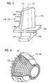
- Figure 3 shows a perspective view of a rotor blade 120 or guide vane 130 of a turbomachine, which extends along a longitudinal axis 121.
- the turbomachine may be a gas turbine of an aircraft or of a power plant for generating electricity, a steam turbine or a compressor.
- the blade or vane 120, 130 has a securing region 400, an adjoining blade or vane platform 403 and a main blade or main part 406 in succession along the longitudinal axis 121.
- the vane 130 may have a further platform (not shown) at its vane tip 415.
- a blade or vane root 183 which is used to secure the rotor blades 120, 130 to a shaft or disk (not shown), is formed in the securing region 400.
- the blade or vane root 183 is designed, for example, in hammerhead form. Other configurations, such as fir-tree or dovetail root, are also possible.
- the blade or vane 120, 130 has a leading edge 409 and a trailing edge 412 for a medium which flows past the main blade or vane part 406.
- blades or vanes 120, 130 by way of example, solid metallic materials, in particular superalloys, are used in all regions 400, 403, 406 of the blade or vane 120, 130.
- superalloys of this type are known, for example, from EP 1 204 776 B1 , EP 1 306 454 , EP 1 319 729 A1 , WO 99/67435 or WO 00/44949 ; these documents form part of the present disclosure with regard to the chemical composition of the alloy.
- the blade or vane 120, 130 may in this case be produced by a casting process, also by means of directional solidification, by a forging process, by a milling process or combinations thereof.
- Single-crystal workpieces of this type are produced, for example, by directional solidification from the melt. This involves casting processes in which the liquid metallic alloy is solidified to form the single-crystal structure, i.e. the single-crystal workpiece, i.e. directionally. In the process, dendritic crystals are formed in the direction of the heat flux and form either a columnar-crystalline grain structure (i.e. with grains which run over the entire length of the workpiece and are referred to in this context, in accordance with the standard terminology, as directionally solidified) or a single-crystal structure, i.e.
- directionally solidified microstructures are referred to in general, this is to be understood as encompassing both single crystals, which do not have any grain boundaries or at most have small-angle grain boundaries, and columnar crystal structures, which do have grain boundaries running in the longitudinal direction, but do not have any transverse grain boundaries. In the case of these latter crystalline structures, it is also possible to refer to directionally solidified microstructures (directionally solidified structures). Processes of this type are known from US 6, 024, 792 and EP 0.892 090 A1 .
- the blades or vanes 120, 130 may also have coatings protecting against corrosion or oxidation, e.g. (MCrAlX; M is at least one element selected from the group consisting of iron (Fe), cobalt (Co), nickel (Ni), X is an active element and stands for yttrium (Y) and/or silicon and/or at least one rare earth element, or hafnium (Hf)). Alloys of this type are known from EP 0 486 489 B1 , EP 0 786 017 B1 , EP 0 412 397 B1 or EP 1 306.454 A1 .
- thermal barrier coating consisting, for example, of ZrO 2 , Y 2 O 9 -ZrO 2 , i.e. which is not, is partially or is completely stabilized by yttrium oxide and/or calcium oxide and/or magnesium oxide, to be present on the MCrAlX.
- Columnar grains are produced in the thermal barrier coating by suitable coating processes, such as for example electron beam physical vapor deposition (EB-PVD).
- refurbishment means that protective layers may have to be removed from components 120, 130 after they have been used (for example by sandblasting). Then, the corrosion and/or oxidation layers or products are removed. If necessary, cracks in the component 120, 130 are also repaired using the solder according to the invention. This is followed by recoating of the component 120, 130, after which the component 120, 130 can be used again.
- the blade or vane 120, 130 may be of solid or hollow design. If the blade or vane 120, 130 is to be cooled, it is hollow and may also include film cooling holes 418 (indicated by dashed lines).
- Figure 4 shows a combustion chamber 110 of a gas turbine 100 ( Fig. 2 ).
- the combustion chamber 110 is configured, for example, as what is known as an annular combustion chamber, in which a multiplicity of burners 107, which are arranged around an axis of rotation 102 in the circumferential direction, open out into a common combustion chamber space 154, with the burners 107 producing flames 156.
- the combustion chamber 110 overall is of annular configuration, positioned around the axis of rotation 102.
- the combustion chamber 110 is designed for a relatively high temperature of the working medium M of approximately 1000°C to 1600°C.
- the combustion chamber wall 153 is provided with an inner lining formed from heat shield elements 155 on its side facing the working medium M.
- Each heat shield element 155 made from an alloy is equipped on the working medium side with a particularly heat-resistant protective layer (MCrAlX layer and/or ceramic coating) or is made from material that is able to withstand high temperatures (solid ceramic bricks).
- MrAlX layer and/or ceramic coating particularly heat-resistant protective layer
- solid ceramic bricks solid ceramic bricks
- M is at least one element selected from the group consisting of iron (Fe), cobalt (Co), nickel (Ni), X is an active element and stands for yttrium (Y) and/or silicon and/or at least one rare earth element, or hafnium (Hf). Alloys of this type are known from EP 0 486 489 B1 , EP 0 786 017 B1 , EP 0 412 397 B1 or EP 1 306 454 A1 , which are intended to form part of the present disclosure with regard to the chemical composition of the alloy.
- a, for example, ceramic thermal barrier coating to be present on the MCrAlX, consisting, for example, of ZrO 2 , Y 2 O 4 -ZrO 2 , i.e. it is not, is partially or is completely stabilized by yttrium oxide and/or calcium oxide and/or magnesium oxide.
- the term refurbishment means that protective layers may have to be removed from heat shield elements 155 after they have been used (for example by sandblasting). Then, the corrosion and/or oxidation layers or products are removed. If necessary, cracks in the heat shield element 155 are also repaired using the solder according to the invention. This is followed by recoating of the heat shield elements 155, after which the heat shield elements 155 can be used again.
- the heat shield elements 155 are in this case, for example, hollow and may also include film cooling holes (not shown) which open out into the combustion chamber space 154.
- Figure 2 shows, by way of example, a gas turbine 100 in the form of a longitudinal part section.
- the gas turbine 100 has a rotor 103, which is mounted such that it can rotate about an axis of rotation 102 and has a shaft, also known as the turbine rotor.
- the annular combustion chamber 110 is in communication with a, for example annular, hot-gas duct 111 where, for example, four successive turbine stages 112 form the turbine 108.
- Each turbine stage 112 is formed, for example, from two blade or vane rings. As seen in the direction of flow of a working medium 113, a row 125 formed from rotor blades 120 follows a row 115 of guide vanes in the hot-gas duct 111.
- the guide vanes 130 are secured to an inner housing 138 of a stator 143, whereas the rotor blades 120 of a row 125 are fitted to the rotor 103, for example by means of a turbine disk 133.
- a generator or machine (not shown) is coupled to the rotor 103.
- the compressor 105 When the gas turbine 100 is operating, the compressor 105 sucks in air 135 through the intake housing 104 and compresses it. The compressed air which is provided at the turbine-side end of the compressor 105 is passed to the burners 107, where it is mixed with a fuel. The mixture is then burnt in the combustion chamber 110 to form the working medium 133. From there, the working medium 133 flows along the hot-gas duct 111 past the guide vanes 130 and the rotor blades 120. The working medium 113 expands at the rotor blades 120, transferring its momentum, so that the rotor blades 120 drive the rotor 103 and the rotor drives the machine coupled to it.
- the components which are exposed to the hot working medium 113 are subject to thermal loads.
- the guide vanes 130 and rotor blades 120 of the first turbine stage 112, as seen in the direction of flow of the working medium 113, together with the heat shield elements which line the annular combustion chamber 110, are subject to the highest thermal loads. To withstand the temperatures prevailing there, these components can be cooled by means of a coolant.
- substrates of the components prefferably have a directional structure, i.e. they are in single-crystal form (SX structure) or include only longitudinally directed grains (DS structure).
- SX structure single-crystal form
- DS structure longitudinally directed grains
- iron-base, nickel-base or cobalt-base superalloys are used as material for the components, in particular for the turbine blades and vanes 120, 130 and components of the combustion chamber 110.
- superalloys of this type are known, for example, from EP 1 204 776 B1 , EP 1 306 454 , EP 1 319 729 A1 , WO 99/67435 or WO 00/44949 .
- the blades and vanes 120, 130 may likewise have coatings to protect against corrosion (MCrAlX; M is at least one element selected from the group consisting of iron (Fe), cobalt (Co), nickel (Ni), X is an active element and stands for yttrium (Y) and/or silicon and/or at least one of the rare earth elements or hafnium). Alloys of this type are known from EP 0 486 489 B1 , EP 0 786 017 B1 , EP 0 412 397 B1 or EP 1 306 454 A1 .
- a thermal barrier coating consisting, for example, of ZrO 2 , Y 2 O 4 -ZrO 2 , i.e. it is not, is partially or is completely stabilized by yttrium oxide and/or calcium oxide and/or magnesium oxide, may also be present on the MCrAlX.
- Columnar grains are produced in the thermal barrier coating by suitable coating processes, such as for example electron beam physical vapor deposition (EB-PVD).
- the guide vane 130 has a guide vane root (not shown here) facing the inner housing 138 of the turbine 108 and a guide vane head on the opposite side from the guide vane root.
- the guide vane head faces the rotor 103 and is fixed to a securing ring 140 of the stator 143.
Landscapes
- Chemical & Material Sciences (AREA)
- Inorganic Chemistry (AREA)
- Engineering & Computer Science (AREA)
- Organic Chemistry (AREA)
- Mechanical Engineering (AREA)
- Metallurgy (AREA)
- Materials Engineering (AREA)
- Chemical Kinetics & Catalysis (AREA)
- Ceramic Engineering (AREA)
- Turbine Rotor Nozzle Sealing (AREA)
- Other Surface Treatments For Metallic Materials (AREA)
- Compositions Of Oxide Ceramics (AREA)
- Coating By Spraying Or Casting (AREA)
Claims (11)
- Système de couches qui comprend :un substrat (4),un enduit (7) métallique de liaison etune couche (16) en céramique à deux strates qui consistent enune strate intérieure en céramique (10) etune strate extérieure en céramique (13),dans lequel seule la couche (10) intérieure en céramique est nanostructurée,dans lequel la couche (10) intérieure en céramique a une porosité allant de 3% en volume à 14% en volume,dans lequel la couche (13) supérieure a une porosité plus grande d'au moins 10 % que la porosité de la couche (10) intérieure,dans lequel le matériau des deux couches (10, 13) en céramique est le même.
- Système de couches suivant la revendication 1,
dans lequel la couche (10) intérieure en céramique est plus mince d'au moins 10 % que la couche (13) extérieure en céramique. - Système de couches suivant la revendication 1 ou 2,
dans lequel la couche (10) intérieure en céramique a une épaisseur allant jusqu'à 100 µm. - Système de couches suivant la revendication 1, 2 ou 3,
dans lequel la couche (10) intérieure en céramique a une épaisseur d'au moins 10 µm. - Système de couches suivant la revendication 1, 2, 3 ou 4,
dans lequel la couche (13) supérieure a une porosité allant jusqu'à 30% en volume, en particulier > 15% en volume à 30% en volume. - Système de couches suivant la revendication 1, 2, 3, 4 ou 5,
dans lequel le matériau de la couche (10) intérieure en céramique comprend de l'oxyde de zirconium. - Système de couches suivant l'une des revendications précédentes, dans lequel la granulométrie maximum d'au moins 90 % des grains de la couche (10) nanostructurée est de 500 nm.
- Système de couches suivant l'une quelconque des revendications précédentes, dans lequel la granulométrie de la couche (10) intérieure est d'au moins 50 nm.
- Système de couches suivant l'une quelconque des revendications précédentes, dans lequel la couche (13) extérieure en céramique a au moins 70% de la granulométrie plus grande que 10µm.
- Système de couches suivant l'une quelconque des revendications précédentes, dans lequel l'enduit (7) de liaison est une couche métallique à deux strates ayant en particulier une quantité réduite d'aluminium (Al) et/ou de chrome (Cr) dans la zone supérieure.
- Système de couches suivant la revendication 10, dans lequel la quantité de chrome (Cr) va de 16% en poids à 18% en poids de chrome (Cr) et/ou celle d'aluminium de 4% en poids à 5% en poids d'aluminium (Al).
Priority Applications (1)
| Application Number | Priority Date | Filing Date | Title |
|---|---|---|---|
| EP20100798799 EP2519659B1 (fr) | 2009-12-29 | 2010-12-21 | Barrière thermique ceramique nano- et microstructurée |
Applications Claiming Priority (3)
| Application Number | Priority Date | Filing Date | Title |
|---|---|---|---|
| EP20090016100 EP2341166A1 (fr) | 2009-12-29 | 2009-12-29 | Barrière thermique ceramique nano- et microstructurée |
| EP20100798799 EP2519659B1 (fr) | 2009-12-29 | 2010-12-21 | Barrière thermique ceramique nano- et microstructurée |
| PCT/EP2010/070347 WO2011080158A1 (fr) | 2009-12-29 | 2010-12-21 | Revêtement de céramique nano- et micro-structuré faisant barrière thermique |
Publications (2)
| Publication Number | Publication Date |
|---|---|
| EP2519659A1 EP2519659A1 (fr) | 2012-11-07 |
| EP2519659B1 true EP2519659B1 (fr) | 2014-06-25 |
Family
ID=41624974
Family Applications (2)
| Application Number | Title | Priority Date | Filing Date |
|---|---|---|---|
| EP20090016100 Withdrawn EP2341166A1 (fr) | 2009-12-29 | 2009-12-29 | Barrière thermique ceramique nano- et microstructurée |
| EP20100798799 Not-in-force EP2519659B1 (fr) | 2009-12-29 | 2010-12-21 | Barrière thermique ceramique nano- et microstructurée |
Family Applications Before (1)
| Application Number | Title | Priority Date | Filing Date |
|---|---|---|---|
| EP20090016100 Withdrawn EP2341166A1 (fr) | 2009-12-29 | 2009-12-29 | Barrière thermique ceramique nano- et microstructurée |
Country Status (7)
| Country | Link |
|---|---|
| US (1) | US20120321905A1 (fr) |
| EP (2) | EP2341166A1 (fr) |
| JP (1) | JP5632017B2 (fr) |
| KR (1) | KR101492313B1 (fr) |
| CN (1) | CN102695818B (fr) |
| RU (1) | RU2518850C2 (fr) |
| WO (1) | WO2011080158A1 (fr) |
Cited By (1)
| Publication number | Priority date | Publication date | Assignee | Title |
|---|---|---|---|---|
| DE102014208216A1 (de) * | 2014-04-30 | 2015-11-05 | Siemens Aktiengesellschaft | CMAS resistente keramische Schicht durch Nanoporosität |
Families Citing this family (17)
| Publication number | Priority date | Publication date | Assignee | Title |
|---|---|---|---|---|
| EP2407579A1 (fr) * | 2010-07-14 | 2012-01-18 | Siemens Aktiengesellschaft | Système poreux de couches en céramique |
| US20130186304A1 (en) * | 2012-01-20 | 2013-07-25 | General Electric Company | Process of fabricating a thermal barrier coating and an article having a cold sprayed thermal barrier coating |
| US20130260132A1 (en) * | 2012-04-02 | 2013-10-03 | United Technologies Corporation | Hybrid thermal barrier coating |
| US20140220324A1 (en) * | 2012-08-15 | 2014-08-07 | Christopher W. Strock | Thermal barrier coating having outer layer |
| US11047033B2 (en) | 2012-09-05 | 2021-06-29 | Raytheon Technologies Corporation | Thermal barrier coating for gas turbine engine components |
| WO2014126633A2 (fr) * | 2012-12-26 | 2014-08-21 | United Technologies Corporation | Revêtement de barrière thermique résistant à l'éclatement |
| US20150233256A1 (en) * | 2013-01-15 | 2015-08-20 | General Electric Company | Novel architectures for ultra low thermal conductivity thermal barrier coatings with improved erosion and impact properties |
| WO2014143363A1 (fr) | 2013-03-14 | 2014-09-18 | United Technologies Corporation | Revêtement de barrière thermique hybride et son procédé de fabrication |
| US9511436B2 (en) | 2013-11-08 | 2016-12-06 | General Electric Company | Composite composition for turbine blade tips, related articles, and methods |
| US20150147524A1 (en) * | 2013-11-26 | 2015-05-28 | Christopher A. Petorak | Modified thermal barrier composite coatings |
| JP6365969B2 (ja) * | 2014-03-17 | 2018-08-01 | 三菱日立パワーシステムズ株式会社 | 遮熱コーティング材、これを有するタービン部材及び遮熱コーティング方法 |
| CN106413626B (zh) | 2014-08-27 | 2020-10-27 | 株式会社Gc | 牙科修补物的制造方法、牙科修补物用二硅酸锂坯料的制造方法和牙科修补物用二硅酸锂坯料 |
| DE102014220359A1 (de) * | 2014-10-08 | 2016-04-14 | Siemens Aktiengesellschaft | Doppellagige Zirkonoxidschicht mit hochreinem Anteil |
| CN105782591A (zh) * | 2014-12-26 | 2016-07-20 | 天津恒实通工程技术发展有限公司 | 一种高隔热效率纳米陶瓷涂层包裹的供热管道 |
| KR101839656B1 (ko) * | 2015-08-13 | 2018-04-26 | 두산중공업 주식회사 | 가스터빈 블레이드 |
| US10801111B2 (en) | 2017-05-30 | 2020-10-13 | Honeywell International Inc. | Sintered-bonded high temperature coatings for ceramic turbomachine components |
| RU2746196C1 (ru) * | 2020-06-01 | 2021-04-08 | Общество С Ограниченной Ответственностью "Технологические Системы Защитных Покрытий" (Ооо "Тсзп") | Деталь и сборочная единица соплового аппарата турбины высокого давления |
Family Cites Families (27)
| Publication number | Priority date | Publication date | Assignee | Title |
|---|---|---|---|---|
| US3649225A (en) * | 1969-11-17 | 1972-03-14 | United Aircraft Corp | Composite coating for the superalloys |
| FR2615871B1 (fr) * | 1987-05-26 | 1989-06-30 | Snecma | Pieces de turbomachine en superalliage comportant un revetement protecteur metalloceramique |
| DE3926479A1 (de) | 1989-08-10 | 1991-02-14 | Siemens Ag | Rheniumhaltige schutzbeschichtung, mit grosser korrosions- und/oder oxidationsbestaendigkeit |
| EP0486489B1 (fr) | 1989-08-10 | 1994-11-02 | Siemens Aktiengesellschaft | Revetement anticorrosion resistant aux temperatures elevees, notamment pour elements de turbines a gaz |
| RU2147624C1 (ru) | 1994-10-14 | 2000-04-20 | Сименс АГ | Защитный слой для защиты детали от коррозии, окисления и термической перегрузки, а также способ его изготовления |
| US6177200B1 (en) * | 1996-12-12 | 2001-01-23 | United Technologies Corporation | Thermal barrier coating systems and materials |
| EP0861927A1 (fr) | 1997-02-24 | 1998-09-02 | Sulzer Innotec Ag | Procédé de fabrication de structures monocristallines |
| EP0892090B1 (fr) | 1997-02-24 | 2008-04-23 | Sulzer Innotec Ag | Procédé de fabrication de structure monocristallines |
| GB9800511D0 (en) * | 1998-01-13 | 1998-03-11 | Rolls Royce Plc | A metallic article having a thermal barrier coating and a method of application thereof |
| WO1999067435A1 (fr) | 1998-06-23 | 1999-12-29 | Siemens Aktiengesellschaft | Alliage a solidification directionnelle a resistance transversale a la rupture amelioree |
| US6231692B1 (en) | 1999-01-28 | 2001-05-15 | Howmet Research Corporation | Nickel base superalloy with improved machinability and method of making thereof |
| EP1204776B1 (fr) | 1999-07-29 | 2004-06-02 | Siemens Aktiengesellschaft | Piece resistant a des temperatures elevees et son procede de production |
| US20030180571A1 (en) * | 1999-12-14 | 2003-09-25 | The Penn State Research Foundation | Microstructured coatings and materials |
| DE50104022D1 (de) | 2001-10-24 | 2004-11-11 | Siemens Ag | Rhenium enthaltende Schutzschicht zum Schutz eines Bauteils gegen Korrosion und Oxidation bei hohen Temperaturen |
| EP1319729B1 (fr) | 2001-12-13 | 2007-04-11 | Siemens Aktiengesellschaft | Pièce résistante à des températures élevées réalisé en superalliage polycristallin ou monocristallin à base de nickel |
| EP1380672A1 (fr) * | 2002-07-09 | 2004-01-14 | Siemens Aktiengesellschaft | Composant à haute résistance contre l'oxydation |
| US6817051B2 (en) * | 2002-08-27 | 2004-11-16 | Sulzer Metco Ag | Guide apparatus for a workpiece having a porous surface coating and a method for the polishing of such a workpiece |
| US7413798B2 (en) * | 2003-04-04 | 2008-08-19 | Siemens Power Generation, Inc. | Thermal barrier coating having nano scale features |
| EP1707651A1 (fr) * | 2005-03-31 | 2006-10-04 | Siemens Aktiengesellschaft | Système de revêtement et procédé de fabrication d'une système de revêtement |
| EP1783248A1 (fr) * | 2005-11-04 | 2007-05-09 | Siemens Aktiengesellschaft | Revêtement de barrière thermique en deux couches contenant une phase pyrochlore |
| EP1806432A1 (fr) * | 2006-01-09 | 2007-07-11 | Siemens Aktiengesellschaft | Système de revêtement avec 2 phases de pyrochlore |
| WO2007112783A1 (fr) * | 2006-04-06 | 2007-10-11 | Siemens Aktiengesellschaft | Revetement stratifie formant une barriere thermique a porosite elevee et composant |
| EP1845171B1 (fr) * | 2006-04-10 | 2016-12-14 | Siemens Aktiengesellschaft | Utilisation de poudres métalliques ayant des particles de taille diverse pour fabriquer un système de couches |
| RU2375499C2 (ru) * | 2007-12-20 | 2009-12-10 | Федеральное государственное унитарное предприятие "Московское машиностроительное производственное предприятие "Салют" | Способ получения многослойного теплозащитного покрытия на деталях из жаропрочных сплавов |
| EP2128306B1 (fr) * | 2008-05-26 | 2015-04-29 | Siemens Aktiengesellschaft | Système de revêtement de barrière thermique en céramique avec deux couches de céramique |
| EP2206805A1 (fr) * | 2009-01-08 | 2010-07-14 | Siemens Aktiengesellschaft | Couche de MCrAIX ayant des teneurs différentes en chrome et aluminium |
| EP2230329A1 (fr) * | 2009-03-18 | 2010-09-22 | Siemens Aktiengesellschaft | Système de couche à double couche poreux doté d'une phase pyrochlore |
-
2009
- 2009-12-29 EP EP20090016100 patent/EP2341166A1/fr not_active Withdrawn
-
2010
- 2010-12-21 RU RU2012132324/02A patent/RU2518850C2/ru not_active IP Right Cessation
- 2010-12-21 CN CN201080059629.3A patent/CN102695818B/zh not_active Expired - Fee Related
- 2010-12-21 KR KR1020127016828A patent/KR101492313B1/ko not_active Expired - Fee Related
- 2010-12-21 WO PCT/EP2010/070347 patent/WO2011080158A1/fr not_active Ceased
- 2010-12-21 EP EP20100798799 patent/EP2519659B1/fr not_active Not-in-force
- 2010-12-21 US US13/519,213 patent/US20120321905A1/en not_active Abandoned
- 2010-12-21 JP JP2012546415A patent/JP5632017B2/ja not_active Expired - Fee Related
Cited By (1)
| Publication number | Priority date | Publication date | Assignee | Title |
|---|---|---|---|---|
| DE102014208216A1 (de) * | 2014-04-30 | 2015-11-05 | Siemens Aktiengesellschaft | CMAS resistente keramische Schicht durch Nanoporosität |
Also Published As
| Publication number | Publication date |
|---|---|
| JP2013515859A (ja) | 2013-05-09 |
| KR101492313B1 (ko) | 2015-02-23 |
| RU2518850C2 (ru) | 2014-06-10 |
| CN102695818A (zh) | 2012-09-26 |
| CN102695818B (zh) | 2015-07-29 |
| EP2519659A1 (fr) | 2012-11-07 |
| JP5632017B2 (ja) | 2014-11-26 |
| RU2012132324A (ru) | 2014-02-10 |
| US20120321905A1 (en) | 2012-12-20 |
| KR20120088874A (ko) | 2012-08-08 |
| WO2011080158A1 (fr) | 2011-07-07 |
| EP2341166A1 (fr) | 2011-07-06 |
Similar Documents
| Publication | Publication Date | Title |
|---|---|---|
| EP2519659B1 (fr) | Barrière thermique ceramique nano- et microstructurée | |
| EP2128306B1 (fr) | Système de revêtement de barrière thermique en céramique avec deux couches de céramique | |
| EP2002030B1 (fr) | Revetement de barriere thermique en couches a forte porosite et composant | |
| US7592071B2 (en) | Layer system | |
| US20210292910A1 (en) | Two layered metallic bondcoat | |
| US8278232B2 (en) | Pyrochlore materials and a thermal barrier coating with these pyrochlore materials | |
| GB2431932A (en) | Thermal barrier coating system incorporating a pyrochlore. | |
| US20090123722A1 (en) | Coating system | |
| US20070186416A1 (en) | Component repair process | |
| US20080138648A1 (en) | Layer system with blocking layer, and production process | |
| GB2439312A (en) | Protective coating for turbine components |
Legal Events
| Date | Code | Title | Description |
|---|---|---|---|
| PUAI | Public reference made under article 153(3) epc to a published international application that has entered the european phase |
Free format text: ORIGINAL CODE: 0009012 |
|
| 17P | Request for examination filed |
Effective date: 20120530 |
|
| AK | Designated contracting states |
Kind code of ref document: A1 Designated state(s): AL AT BE BG CH CY CZ DE DK EE ES FI FR GB GR HR HU IE IS IT LI LT LU LV MC MK MT NL NO PL PT RO RS SE SI SK SM TR |
|
| RAP1 | Party data changed (applicant data changed or rights of an application transferred) |
Owner name: SIEMENS AKTIENGESELLSCHAFT |
|
| DAX | Request for extension of the european patent (deleted) | ||
| 17Q | First examination report despatched |
Effective date: 20131104 |
|
| GRAP | Despatch of communication of intention to grant a patent |
Free format text: ORIGINAL CODE: EPIDOSNIGR1 |
|
| INTG | Intention to grant announced |
Effective date: 20140129 |
|
| GRAS | Grant fee paid |
Free format text: ORIGINAL CODE: EPIDOSNIGR3 |
|
| GRAA | (expected) grant |
Free format text: ORIGINAL CODE: 0009210 |
|
| AK | Designated contracting states |
Kind code of ref document: B1 Designated state(s): AL AT BE BG CH CY CZ DE DK EE ES FI FR GB GR HR HU IE IS IT LI LT LU LV MC MK MT NL NO PL PT RO RS SE SI SK SM TR |
|
| REG | Reference to a national code |
Ref country code: GB Ref legal event code: FG4D |
|
| REG | Reference to a national code |
Ref country code: CH Ref legal event code: EP |
|
| REG | Reference to a national code |
Ref country code: AT Ref legal event code: REF Ref document number: 674777 Country of ref document: AT Kind code of ref document: T Effective date: 20140715 |
|
| REG | Reference to a national code |
Ref country code: IE Ref legal event code: FG4D |
|
| REG | Reference to a national code |
Ref country code: DE Ref legal event code: R096 Ref document number: 602010017092 Country of ref document: DE Effective date: 20140807 |
|
| REG | Reference to a national code |
Ref country code: CH Ref legal event code: NV Representative=s name: SIEMENS SCHWEIZ AG, CH |
|
| PG25 | Lapsed in a contracting state [announced via postgrant information from national office to epo] |
Ref country code: NO Free format text: LAPSE BECAUSE OF FAILURE TO SUBMIT A TRANSLATION OF THE DESCRIPTION OR TO PAY THE FEE WITHIN THE PRESCRIBED TIME-LIMIT Effective date: 20140925 Ref country code: GR Free format text: LAPSE BECAUSE OF FAILURE TO SUBMIT A TRANSLATION OF THE DESCRIPTION OR TO PAY THE FEE WITHIN THE PRESCRIBED TIME-LIMIT Effective date: 20140926 Ref country code: CY Free format text: LAPSE BECAUSE OF FAILURE TO SUBMIT A TRANSLATION OF THE DESCRIPTION OR TO PAY THE FEE WITHIN THE PRESCRIBED TIME-LIMIT Effective date: 20140625 Ref country code: FI Free format text: LAPSE BECAUSE OF FAILURE TO SUBMIT A TRANSLATION OF THE DESCRIPTION OR TO PAY THE FEE WITHIN THE PRESCRIBED TIME-LIMIT Effective date: 20140625 Ref country code: LT Free format text: LAPSE BECAUSE OF FAILURE TO SUBMIT A TRANSLATION OF THE DESCRIPTION OR TO PAY THE FEE WITHIN THE PRESCRIBED TIME-LIMIT Effective date: 20140625 |
|
| REG | Reference to a national code |
Ref country code: AT Ref legal event code: MK05 Ref document number: 674777 Country of ref document: AT Kind code of ref document: T Effective date: 20140625 |
|
| REG | Reference to a national code |
Ref country code: NL Ref legal event code: VDEP Effective date: 20140625 |
|
| REG | Reference to a national code |
Ref country code: LT Ref legal event code: MG4D |
|
| PG25 | Lapsed in a contracting state [announced via postgrant information from national office to epo] |
Ref country code: SE Free format text: LAPSE BECAUSE OF FAILURE TO SUBMIT A TRANSLATION OF THE DESCRIPTION OR TO PAY THE FEE WITHIN THE PRESCRIBED TIME-LIMIT Effective date: 20140625 Ref country code: LV Free format text: LAPSE BECAUSE OF FAILURE TO SUBMIT A TRANSLATION OF THE DESCRIPTION OR TO PAY THE FEE WITHIN THE PRESCRIBED TIME-LIMIT Effective date: 20140625 Ref country code: HR Free format text: LAPSE BECAUSE OF FAILURE TO SUBMIT A TRANSLATION OF THE DESCRIPTION OR TO PAY THE FEE WITHIN THE PRESCRIBED TIME-LIMIT Effective date: 20140625 Ref country code: RS Free format text: LAPSE BECAUSE OF FAILURE TO SUBMIT A TRANSLATION OF THE DESCRIPTION OR TO PAY THE FEE WITHIN THE PRESCRIBED TIME-LIMIT Effective date: 20140625 |
|
| PG25 | Lapsed in a contracting state [announced via postgrant information from national office to epo] |
Ref country code: ES Free format text: LAPSE BECAUSE OF FAILURE TO SUBMIT A TRANSLATION OF THE DESCRIPTION OR TO PAY THE FEE WITHIN THE PRESCRIBED TIME-LIMIT Effective date: 20140625 Ref country code: EE Free format text: LAPSE BECAUSE OF FAILURE TO SUBMIT A TRANSLATION OF THE DESCRIPTION OR TO PAY THE FEE WITHIN THE PRESCRIBED TIME-LIMIT Effective date: 20140625 Ref country code: SK Free format text: LAPSE BECAUSE OF FAILURE TO SUBMIT A TRANSLATION OF THE DESCRIPTION OR TO PAY THE FEE WITHIN THE PRESCRIBED TIME-LIMIT Effective date: 20140625 Ref country code: RO Free format text: LAPSE BECAUSE OF FAILURE TO SUBMIT A TRANSLATION OF THE DESCRIPTION OR TO PAY THE FEE WITHIN THE PRESCRIBED TIME-LIMIT Effective date: 20140625 Ref country code: CZ Free format text: LAPSE BECAUSE OF FAILURE TO SUBMIT A TRANSLATION OF THE DESCRIPTION OR TO PAY THE FEE WITHIN THE PRESCRIBED TIME-LIMIT Effective date: 20140625 Ref country code: PT Free format text: LAPSE BECAUSE OF FAILURE TO SUBMIT A TRANSLATION OF THE DESCRIPTION OR TO PAY THE FEE WITHIN THE PRESCRIBED TIME-LIMIT Effective date: 20141027 |
|
| PG25 | Lapsed in a contracting state [announced via postgrant information from national office to epo] |
Ref country code: PL Free format text: LAPSE BECAUSE OF FAILURE TO SUBMIT A TRANSLATION OF THE DESCRIPTION OR TO PAY THE FEE WITHIN THE PRESCRIBED TIME-LIMIT Effective date: 20140625 Ref country code: AT Free format text: LAPSE BECAUSE OF FAILURE TO SUBMIT A TRANSLATION OF THE DESCRIPTION OR TO PAY THE FEE WITHIN THE PRESCRIBED TIME-LIMIT Effective date: 20140625 Ref country code: IS Free format text: LAPSE BECAUSE OF FAILURE TO SUBMIT A TRANSLATION OF THE DESCRIPTION OR TO PAY THE FEE WITHIN THE PRESCRIBED TIME-LIMIT Effective date: 20141025 Ref country code: NL Free format text: LAPSE BECAUSE OF FAILURE TO SUBMIT A TRANSLATION OF THE DESCRIPTION OR TO PAY THE FEE WITHIN THE PRESCRIBED TIME-LIMIT Effective date: 20140625 |
|
| REG | Reference to a national code |
Ref country code: DE Ref legal event code: R097 Ref document number: 602010017092 Country of ref document: DE |
|
| PG25 | Lapsed in a contracting state [announced via postgrant information from national office to epo] |
Ref country code: DK Free format text: LAPSE BECAUSE OF FAILURE TO SUBMIT A TRANSLATION OF THE DESCRIPTION OR TO PAY THE FEE WITHIN THE PRESCRIBED TIME-LIMIT Effective date: 20140625 |
|
| PLBE | No opposition filed within time limit |
Free format text: ORIGINAL CODE: 0009261 |
|
| STAA | Information on the status of an ep patent application or granted ep patent |
Free format text: STATUS: NO OPPOSITION FILED WITHIN TIME LIMIT |
|
| 26N | No opposition filed |
Effective date: 20150326 |
|
| PG25 | Lapsed in a contracting state [announced via postgrant information from national office to epo] |
Ref country code: BE Free format text: LAPSE BECAUSE OF FAILURE TO SUBMIT A TRANSLATION OF THE DESCRIPTION OR TO PAY THE FEE WITHIN THE PRESCRIBED TIME-LIMIT Effective date: 20140625 |
|
| PG25 | Lapsed in a contracting state [announced via postgrant information from national office to epo] |
Ref country code: LU Free format text: LAPSE BECAUSE OF FAILURE TO SUBMIT A TRANSLATION OF THE DESCRIPTION OR TO PAY THE FEE WITHIN THE PRESCRIBED TIME-LIMIT Effective date: 20141221 |
|
| REG | Reference to a national code |
Ref country code: IE Ref legal event code: MM4A |
|
| PG25 | Lapsed in a contracting state [announced via postgrant information from national office to epo] |
Ref country code: IE Free format text: LAPSE BECAUSE OF NON-PAYMENT OF DUE FEES Effective date: 20141221 |
|
| PG25 | Lapsed in a contracting state [announced via postgrant information from national office to epo] |
Ref country code: SI Free format text: LAPSE BECAUSE OF FAILURE TO SUBMIT A TRANSLATION OF THE DESCRIPTION OR TO PAY THE FEE WITHIN THE PRESCRIBED TIME-LIMIT Effective date: 20140625 |
|
| REG | Reference to a national code |
Ref country code: FR Ref legal event code: PLFP Year of fee payment: 6 |
|
| PGFP | Annual fee paid to national office [announced via postgrant information from national office to epo] |
Ref country code: GB Payment date: 20151209 Year of fee payment: 6 |
|
| PGFP | Annual fee paid to national office [announced via postgrant information from national office to epo] |
Ref country code: FR Payment date: 20151214 Year of fee payment: 6 |
|
| PG25 | Lapsed in a contracting state [announced via postgrant information from national office to epo] |
Ref country code: SM Free format text: LAPSE BECAUSE OF FAILURE TO SUBMIT A TRANSLATION OF THE DESCRIPTION OR TO PAY THE FEE WITHIN THE PRESCRIBED TIME-LIMIT Effective date: 20140625 |
|
| PGFP | Annual fee paid to national office [announced via postgrant information from national office to epo] |
Ref country code: CH Payment date: 20160302 Year of fee payment: 6 Ref country code: DE Payment date: 20160219 Year of fee payment: 6 Ref country code: IT Payment date: 20151228 Year of fee payment: 6 |
|
| PG25 | Lapsed in a contracting state [announced via postgrant information from national office to epo] |
Ref country code: MC Free format text: LAPSE BECAUSE OF FAILURE TO SUBMIT A TRANSLATION OF THE DESCRIPTION OR TO PAY THE FEE WITHIN THE PRESCRIBED TIME-LIMIT Effective date: 20140625 |
|
| PG25 | Lapsed in a contracting state [announced via postgrant information from national office to epo] |
Ref country code: BG Free format text: LAPSE BECAUSE OF FAILURE TO SUBMIT A TRANSLATION OF THE DESCRIPTION OR TO PAY THE FEE WITHIN THE PRESCRIBED TIME-LIMIT Effective date: 20140625 |
|
| PG25 | Lapsed in a contracting state [announced via postgrant information from national office to epo] |
Ref country code: HU Free format text: LAPSE BECAUSE OF FAILURE TO SUBMIT A TRANSLATION OF THE DESCRIPTION OR TO PAY THE FEE WITHIN THE PRESCRIBED TIME-LIMIT; INVALID AB INITIO Effective date: 20101221 Ref country code: MT Free format text: LAPSE BECAUSE OF FAILURE TO SUBMIT A TRANSLATION OF THE DESCRIPTION OR TO PAY THE FEE WITHIN THE PRESCRIBED TIME-LIMIT Effective date: 20140625 Ref country code: TR Free format text: LAPSE BECAUSE OF FAILURE TO SUBMIT A TRANSLATION OF THE DESCRIPTION OR TO PAY THE FEE WITHIN THE PRESCRIBED TIME-LIMIT Effective date: 20140625 |
|
| REG | Reference to a national code |
Ref country code: DE Ref legal event code: R119 Ref document number: 602010017092 Country of ref document: DE |
|
| REG | Reference to a national code |
Ref country code: CH Ref legal event code: PL |
|
| GBPC | Gb: european patent ceased through non-payment of renewal fee |
Effective date: 20161221 |
|
| REG | Reference to a national code |
Ref country code: FR Ref legal event code: ST Effective date: 20170831 |
|
| PG25 | Lapsed in a contracting state [announced via postgrant information from national office to epo] |
Ref country code: IT Free format text: LAPSE BECAUSE OF NON-PAYMENT OF DUE FEES Effective date: 20161221 Ref country code: CH Free format text: LAPSE BECAUSE OF NON-PAYMENT OF DUE FEES Effective date: 20161231 Ref country code: FR Free format text: LAPSE BECAUSE OF NON-PAYMENT OF DUE FEES Effective date: 20170102 Ref country code: LI Free format text: LAPSE BECAUSE OF NON-PAYMENT OF DUE FEES Effective date: 20161231 |
|
| PG25 | Lapsed in a contracting state [announced via postgrant information from national office to epo] |
Ref country code: GB Free format text: LAPSE BECAUSE OF NON-PAYMENT OF DUE FEES Effective date: 20161221 Ref country code: DE Free format text: LAPSE BECAUSE OF NON-PAYMENT OF DUE FEES Effective date: 20170701 |
|
| PG25 | Lapsed in a contracting state [announced via postgrant information from national office to epo] |
Ref country code: MK Free format text: LAPSE BECAUSE OF FAILURE TO SUBMIT A TRANSLATION OF THE DESCRIPTION OR TO PAY THE FEE WITHIN THE PRESCRIBED TIME-LIMIT Effective date: 20140625 |
|
| PG25 | Lapsed in a contracting state [announced via postgrant information from national office to epo] |
Ref country code: AL Free format text: LAPSE BECAUSE OF FAILURE TO SUBMIT A TRANSLATION OF THE DESCRIPTION OR TO PAY THE FEE WITHIN THE PRESCRIBED TIME-LIMIT Effective date: 20140625 |