EP2520005B1 - Procédé de fabrication d'un stator segmenté comprenant l'étape de bobinage et stator correspondant - Google Patents
Procédé de fabrication d'un stator segmenté comprenant l'étape de bobinage et stator correspondant Download PDFInfo
- Publication number
- EP2520005B1 EP2520005B1 EP10774195.1A EP10774195A EP2520005B1 EP 2520005 B1 EP2520005 B1 EP 2520005B1 EP 10774195 A EP10774195 A EP 10774195A EP 2520005 B1 EP2520005 B1 EP 2520005B1
- Authority
- EP
- European Patent Office
- Prior art keywords
- stator
- coil
- winding
- segment
- coil element
- Prior art date
- Legal status (The legal status is an assumption and is not a legal conclusion. Google has not performed a legal analysis and makes no representation as to the accuracy of the status listed.)
- Active
Links
Images


Classifications
-
- H—ELECTRICITY
- H02—GENERATION; CONVERSION OR DISTRIBUTION OF ELECTRIC POWER
- H02K—DYNAMO-ELECTRIC MACHINES
- H02K15/00—Processes or apparatus specially adapted for manufacturing, assembling, maintaining or repairing of dynamo-electric machines
- H02K15/08—Forming windings by laying conductors into or around core parts
- H02K15/095—Forming windings by laying conductors into or around core parts by laying conductors around salient poles
-
- H—ELECTRICITY
- H02—GENERATION; CONVERSION OR DISTRIBUTION OF ELECTRIC POWER
- H02K—DYNAMO-ELECTRIC MACHINES
- H02K15/00—Processes or apparatus specially adapted for manufacturing, assembling, maintaining or repairing of dynamo-electric machines
- H02K15/02—Processes or apparatus specially adapted for manufacturing, assembling, maintaining or repairing of dynamo-electric machines of stator or rotor bodies
- H02K15/021—Magnetic cores
- H02K15/022—Magnetic cores with salient poles
-
- H—ELECTRICITY
- H02—GENERATION; CONVERSION OR DISTRIBUTION OF ELECTRIC POWER
- H02K—DYNAMO-ELECTRIC MACHINES
- H02K2203/00—Specific aspects not provided for in the other groups of this subclass relating to the windings
- H02K2203/06—Machines characterised by the wiring leads, i.e. conducting wires for connecting the winding terminations
-
- H—ELECTRICITY
- H02—GENERATION; CONVERSION OR DISTRIBUTION OF ELECTRIC POWER
- H02K—DYNAMO-ELECTRIC MACHINES
- H02K2203/00—Specific aspects not provided for in the other groups of this subclass relating to the windings
- H02K2203/12—Machines characterised by the bobbins for supporting the windings
-
- H—ELECTRICITY
- H02—GENERATION; CONVERSION OR DISTRIBUTION OF ELECTRIC POWER
- H02K—DYNAMO-ELECTRIC MACHINES
- H02K3/00—Details of windings
- H02K3/04—Windings characterised by the conductor shape, form or construction, e.g. with bar conductors
- H02K3/28—Layout of windings or of connections between windings
Definitions
- a manufacturing method for a stator has become known in which a plurality of individual separate stator cores are wound before they are assembled to form a common stator.
- Two partial cores are arranged opposite one another on a common axis for winding.
- a connecting wire between the two part cores is arranged axially above the part cores, transversely to the radial inner space, when the part cores are arranged in relation to the stator.
- these connecting wires are pressed axially outwards and axially against the part cores.
- Stators of electrical machines have become known in which several sub-coils of separately manufactured stator segments are wound through by means of an uninterrupted winding wire.
- the WO 01 / 99254A1 describes an electric motor with individual stator segments, the windings of which are combined individually or in blocks to form a connection with an energy supply.
- the DE 10 2006 021 903 A1 describes an insulating mask for a stator tooth, in which the winding wire of the coil is guided radially outward through slots in the insulating lamella and is connected to an adjacent coil here by means of a connection element.
- EP 1 780 868 A1 discloses a stator of an electrical machine in which individual stator teeth are fixedly connected to one another in an articulated manner via a deformable yoke. Several individual tooth coils of the stator teeth are wound through by means of an uninterrupted wire. With the DE 10 2008 054 527 A1 a stator with separately manufactured stator segments has become known, the stator teeth of which are wound as individual tooth coils. The coil beginning and the coil end are connected to a connection plate by means of insulation displacement connections.
- stator according to the invention and the method according to the invention for manufacturing a stator with the features of the independent claims has the advantage that when separately manufactured stator segments with wound uninterrupted partial coils are arranged directly next to one another, the connecting wire between the partial coils with the arrangement of the stator segments in its final assembly position is brought. As a result, on the one hand, the subsequent wiring effort for the partial coils is reduced and, on the other hand, an additional assembly step for the final positioning of the connecting wires is omitted.
- the production of such partial coils, which are adjacent in the circumferential direction, as twin coils thus allows a possibility of variation, which is advantageous in terms of assembly, for electrical machines with different electrical winding phases.
- the insulating mask protrudes axially beyond the circle segments, radial slots through which the coil wire is guided are arranged in this area.
- the connecting wire between the two sub-coils is guided radially outward through a first axial recess in the first stator segment and again radially inward through a further radial recess in the insulating mask of the second stator segment.
- the connecting wire runs radially outside of the insulating masks, which saves axial installation space and no further separate assembly step is necessary for positioning the connecting wires between the partial coils.
- This connecting wire running radially outside the insulating mask simultaneously represents a hinge-like connection between the two stator segments, by means of which the stator segments can be pivoted after they have been wound.
- the connecting wires are arranged axially within the maximum axial extent of the insulating masks.
- twin coils can be wound particularly advantageously in that the tooth axes of the two stator segments deviate from the axial direction of the fully assembled stator during winding. During the winding process, the tooth axes do not intersect radially within the stator ring.
- the radially outer circular segments of the stator segments are arranged adjacent, the tooth axes preferably not being aligned in parallel.
- tooth axes form a so-called winding angle between 40 ° and 120 ° with respect to the center of the circle of the fully assembled stator ring.
- a winding angle between 60 ° and 90 ° is particularly preferred.
- the second stator segment After the second stator segment has been wound, it can be pivoted in a particularly simple manner with respect to the first stator segment, so that the winding angle is closed.
- the two stator segments are rotated against each other until the tooth axes intersect approximately in the center of the stator ring.
- the tooth axes of this twin coil are already aligned in the radial direction before the stator ring is completely assembled.
- the connecting wire between the two partial coils acts as a kind of joint or hinge around which the two stator teeth are rotated.
- winding arrangement of the two stator elements is around So much free space around both stator teeth that different winding techniques, such as a coil winding technique or needle winding or flyer winding, can be used.
- the two coils can also be wound in the same or opposite direction as desired.
- stator segments as stator teeth with adjoining circular segments so that magnetically conductive T-pieces are created.
- These can preferably be constructed from individual lamellar plates in the axial direction.
- the latter have an insulating mask which, for example, is designed in two parts and is pushed onto the stator elements in the axial direction.
- the third or further partial coil is preferably arranged at a distance from the twin coil in the circumferential direction, in such a way that partial coils of another winding phase are arranged between them.
- the third stator segment with the uninterrupted coil wire is preferably arranged offset by about 120 ° to the second stator element.
- the connecting wires between the continuously wound sub-coils in the circumferential direction outside the insulating masks.
- stator segments After winding, the individual stator segments can advantageously be welded to one another in the area of the circular segments. As a further connection option for the stator segments, they can be clamped in a ring or glued together.
- a stator manufactured using this manufacturing method can, on the one hand, achieve a higher fill factor of the winding and, at the same time, the interconnection expense of the individual partial coils can be reduced.
- so-called twin coils consisting of two directly adjacent, directly wound partial coils, are arranged in the circular ring of the stator.
- the stator has six winding phases, each with three sub-coils, for example.
- a twin coil is arranged in each winding phase, with a third or, optionally, further sub-coil being wound continuously. It is advantageous here to connect two winding phases in parallel so that the stator has three electrical phases.
- the stator is advantageously used for an electrical machine in which the rotor has integrated permanent magnets.
- These permanent magnets can for example be arranged like spokes (longitudinal direction of the magnets in radial direction) or tangential (longitudinal direction in circumferential direction).
- the stator of the electric motor can for example be glued into a housing part at low cost.
- FIG. 1 An electric motor is shown schematically as an example of an electric machine 10, in which a rotor 13 is rotatably arranged within a stator 12.
- the rotor 13 here has permanent magnets 22, which are arranged, for example, with their longitudinal direction in the radial direction 30 or with their longitudinal direction in the circumferential direction 31.
- the electric motor is designed, for example, as an internal rotor, in which the stator 12 is firmly fixed in a housing part 11, for example glued in.
- the stator 12 is composed of individual stator segments 14 and forms a circular ring 15, in the interior of which the rotor 13 is rotatably mounted on an axis of rotation 32.
- stator segments 14 are first wound with partial coils 17, 19, 21 before the stator segments 14 are firmly connected to form the circular ring 24.
- the stator segments 14 each have a stator tooth 26 and a circular segment 28, which are made of magnetically conductive material and form a magnetic core 29.
- the stator tooth 26 is connected to the circular segment 28, so that the stator segment is T-shaped.
- This magnetic core 29 of the stator segment 14 is composed, for example, of individual laminations 34 in the axial direction 33.
- the individual stator segments 14 are shown in the exemplary embodiment Figure 1 connected to one another, for example, by means of weld seams 36 which are formed between the circular segments 28 in the longitudinal direction 33.
- the individual stator segments 14 can also be glued to one another or braced directly in a clamping ring, for example in the housing part 11.
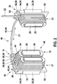
- FIG Figure 2 shows a winding phase 40 according to the invention according to the embodiment of FIG Figure 1 .
- a first stator segment 16 with a first partial coil 17 is arranged immediately adjacent to a second stator segment 18 with a second partial coil 19.
- the first coil section 17 is connected to the second coil section 19 by means of a connecting wire 42, the two coil sections 17, 19 being continuously wound with a continuous coil wire 44.
- the partial coils 17, 19 directly adjacent in the circumferential direction 31 are also referred to as twin coils 46.
- the first coil section 17 has a wire feed 48 and is wound counterclockwise.
- the second sub-coil 19 begins with the connecting wire 42 and is wound clockwise. That is, the two sub-coils 17, 19 of the Twin coil 46 are wound in opposite directions.
- the two sub-coils 17, 19 are shown with a winding in the same direction.
- the end of the second coil section 19 merges into a second connecting wire 43, which leads uninterruptedly to a third coil section 21, which is arranged at a distance in the circumferential direction 31.
- the third coil section 21 here has a wire outlet 52, so that the winding strand 40 shown with the wire feed 48 and the wire outlet 52 comprises three coil sections 15 with an uninterrupted coil wire 44 wound through.
- the stator 12 according to Figure 1 has eighteen stator segments 14 with eighteen partial coils 15.
- the third stator segment 20 is arranged, for example, approximately 120 ° offset with respect to the second stator segment 18 in the circular ring 24.
- Insulating masks 54 are arranged on the stator teeth 26 of the stator segments 14 and insulate the magnetic core 29 from the coil wire 44.
- the insulating masks 54 are made of plastic, for example. Due to the two-part design of the insulating mask 54, the two parts can be pushed onto the stator teeth 26 in the axial direction 33. The insulating mask 54 projects beyond the magnetic core 29 in the axial direction 33, so that a radially outer boundary 55 is arranged for the partial coils 15.
- FIG 3 an embodiment of a twin coil 46 is shown, in which the first coil section 17 is also continuously wound together with the second coil section 19 with a continuous coil wire 44.
- the connecting wire 42 between the first and the second sub-coil 17, 19 is guided radially outward through radial cutouts 58 in the insulating mask 54.
- the connecting wire 42 between the first and the second sub-coil 17, 19 is already arranged radially outside the insulating mask 54 during the winding process and also after the stator segments 14 have been assembled.
- the connecting wire 42 is arranged axially below the upper edge 60 of the insulating mask 54, so that the connecting wire 42 does not extend over the axial dimensions of the insulating mask 54 with respect to the axial direction 33.
- the first and the second stator segments 16, 18 are shown here in the pre-assembled state, in which the tooth axes 62 of the two stator segments 16, 18 intersect in the radial center point 64 of the stator 12. With this arrangement of the two stator segments 16, 18, the tooth axes 62 lie in the radial direction 30, the tooth axes 62 intersecting radially within the circular ring 24.
- the radial recesses 58 are also in Figure 2 shown, with no coil wire 44 being passed through these recesses 58 there.
- Each insulating mask 54 has on its upper edge 60 two radial cutouts 58 offset in the circumferential direction 31, which are designed as slots 59, for example.
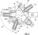
- FIG. 4 a device for winding the stator segments 14 is shown, on the basis of which the winding method is explained.
- these are arranged in such a way that their two tooth axes 62 intersect radially outside of the insulating mask 54 at point 65.
- the two tooth axes 62 point away from one another radially within the stator segments 14, so that these according to FIG Figure 4 approximately form a winding angle 66 between 60 ° and 90 °.
- both coil sections 17, 19 can be wound in one piece by means of an uninterrupted coil wire 44.
- a third stator segment 20 is arranged, onto which a third partial coil 21 is wound in one piece.
- a second connecting wire 43 is arranged between the second coil section 19 and the third coil section 21, which wire runs radially outside of the insulating masks 54 with respect to the finished assembly position of the stator elements 14.
- the length of the second connecting wire 43 can be adjusted variably by a spacer 68.
- the wire guide is shown schematically for the formation of an opposing winding of the two partial coils 17, 19.
- the starting point 48 of the coil wire 44 is fixed in a first holding element 70 and leads via a deflection element 72 radially from the outside to the inside through a Slot 59, which is arranged in plan view on the left side of the insulating mask 54 (in the circumferential direction 31).
- the coil wire 44 is wound clockwise onto the insulating mask 54 from the perspective of the stator center point 64 and is guided radially to the outside of the insulating mask 54 through a slot 59 arranged on the right-hand side.
- the coil wire 44 is passed around a further deflection element 73 and the insulating mask 54 of the second stator segment 18 is guided radially inward through a slot 59 on the right side of the insulating mask 54, viewed from the center 64, to be wound clockwise here.
- the coil wire 44 is then passed through the left slot 59 radially outside of the radial boundary 55 and directed radially from the outside via the spacer 68 to the inside of the insulating mask 54 of the third stator segment 20 in order to form the third coil section 21 there.
- the wire outlet 52 is in turn guided radially through a slot 59 to the outside (radially outside of the circular ring 24 of the insulating mask 54, in order to end at the starting point 50 (at the holding element 70) Fig. 4 represented by arrows of the coil wire 44.
- the stator segments 16 and 18 are then pivoted relative to one another in such a way that their two tooth axes 62 rotate towards one another with respect to the center point 64 until they finally cross at the center point 64.
- the two circular segments 28 of the two stator segments 16, 18 are moved towards one another in such a way that their side surfaces 76 abut one another in the circumferential direction 31.
- the connecting wire 42 of the two partial coils 17, 19 remains arranged radially outside of the insulating mask 54 both during winding and in the final assembly position.
- the connecting wire 42 serves as a joint or hinge during the pivoting, by means of which the two stator segments 16, 18 are movably connected to one another.
- stator segments 16, 18, 20 For winding the stator segments 16, 18, 20, these are received in a winding device 80 in which the winding angle 66 between the partial coils 17, 19, 21 is adjustable.
- the stator segments 16, 18, 20 are clamped onto a receiving plate 82 in such a way that the outside 84 (with respect to the circular ring 24) of the stator segments 16, 18, 20 and the insulating masks 54 point towards the center (point 65) of the receiving plate 82.
- the stator segments 16, 18, 20 are rotatably mounted about the tooth axes 62, the stator teeth 26 being rotated about the tooth axes 62 for winding.
- the connecting wires 42, 43 run here radially outside of the insulating masks 54, that is to say between the outer sides 84 of the stator segments 16, 18, 20.
- the mounting plate 82 is rotatably mounted on a drive shaft 86.
- the stator segment 16, 18, 20 to be wound can be aligned with its tooth axis 62 parallel to the drive shaft 86.
- the entire receiving plate 84 with all stator segments 16, 18, 20 is then rotated around the drive shaft 86.
- stator elements 14 and the partial coils 15 can be varied according to the application.
- only one twin coil 46 can be wound continuously in a winding strand 40 and further sub-coils can be electrically connected after the connection of the stator segments 14 by means of separate electrical connections or interconnection elements.
- the interconnection of the individual winding phases can also be carried out in parallel or in series in order to form the corresponding electrical phases - in particular a brushless direct current motor (EC motor).
- the manufacturing principle of the stator 12 can in principle also be applied to a rotor which is designed as an external rotor.
- the drive unit 10 according to the invention is preferably used to adjust moving parts in the motor vehicle - for example as a power steering motor - but is not restricted to such an application.
Landscapes
- Engineering & Computer Science (AREA)
- Manufacturing & Machinery (AREA)
- Power Engineering (AREA)
- Manufacture Of Motors, Generators (AREA)
- Windings For Motors And Generators (AREA)
Claims (13)
- Procédé permettant de fabriquer un stator (12) sur lequel sont disposés plusieurs faisceaux de bobinage électriques (40) dotés de parties de bobine individuelles (15), caractérisé par les étapes suivantes :- production de plusieurs segments de stator séparés (14) qui comprennent des masques isolants (54),- bobinage d'un premier segment de stator (16) doté d'une première partie de bobine (17),- bobinage d'un deuxième segment de stator (18) doté d'une deuxième partie de bobine (19) avec un fil de bobinage (44) ininterrompu bobiné,- bobinage d'un troisième segment de stator (20) doté d'une troisième partie de bobine (21) avec le fil de bobinage (44) ininterrompu bobiné,- agencement des premier et deuxième segments de stator (16, 18) dotés de la première et de la deuxième partie de bobine (17, 19) de manière directement voisine dans la direction périphérique (31) du stator (12),- agencement d'autres segments de stator (20) en un anneau circulaire (24),- liaison mécanique des segments de stator individuels (16, 18, 20),- dans lequel les masques isolants (54) comprennent des évidements radiaux (58) à travers lesquels le fil de liaison (42) entre la première et la deuxième partie de bobine (17, 19) est guidé dans la direction radiale (30), lesquelles parties de bobine forment conjointement une bobine double (46),- dans lequel le fil de liaison (42) est disposé radialement à l'extérieur des masques isolants (54) avant le bobinage du deuxième segment de stator (18),- dans lequel le fil de liaison (42) ne dépasse pas au-delà du masque isolant (54) par rapport à une direction axiale (33) du stator (12) lors du bobinage et- dans lequel le fil de liaison (42) entre la première et la deuxième partie de bobine (17, 19) et le fil de liaison (43) entre la deuxième partie de bobine (19) et la troisième partie de bobine (21) demeurent radialement à l'extérieur du masque isolant (54) également une fois le montage fini.
- Procédé permettant de fabriquer un stator (12) selon la revendication 1, caractérisé en ce que chaque segment de stator (14) comprend un segment circulaire (28) doté d'une dent de stator (26) le long d'un axe de dent (62), les axes (62) des dents de stator (26) étant, à l'état relié prémonté des segments de stator (14), orientés le long d'une direction radiale (30) vers le centre (64) de l'anneau circulaire (24), et pendant le bobinage du deuxième segment de stator (18), la position de l'axe de dent (62) du deuxième segment de stator (18) différant de la direction radiale (30), et étant orientée en particulier de manière non parallèle à l'axe de dent (62) du premier élément de stator (16).
- Procédé permettant de fabriquer un stator (12) selon l'une des revendications précédentes, caractérisé en ce que, pendant le bobinage du deuxième segment de stator (18), les premier et deuxième axes de dent (62) forment un angle de bobinage (66) [point d'intersection (65) des axes de dent (62) radialement à l'extérieur des segments de stator (14)] compris entre 40° et 120°, en particulier entre 60° et 90°.
- Procédé permettant de fabriquer un stator (12) selon l'une des revendications précédentes, caractérisé en ce que le deuxième segment de stator (18), après son bobinage, est pivoté par rapport au premier segment de stator (16) de telle sorte que l'axe de dent (62) du deuxième segment de stator (18) soit disposé dans la direction radiale (30), le fil de bobinage (44) entre le premier et le deuxième segment de stator (16, 18) étant réalisé en tant que fil de liaison (42) qui agit en tant qu'articulation ou charnière en particulier lors du pivotement.
- Procédé permettant de fabriquer un stator (12) selon l'une des revendications précédentes, caractérisé en ce que la première et la deuxième partie de bobine (17, 19) sont bobinées en sens contraires, en particulier par bobinage flyer.
- Procédé permettant de fabriquer un stator (12) selon l'une des revendications précédentes, caractérisé en ce que les parties de bobine (15) sont bobinées sur des masques isolants (54) qui entourent les dents de stator (26) et en particulier les dents de stator (26) sont réalisées en tant que tôles en lamelles (34) en forme de T avec les segments circulaires (28).
- Procédé permettant de fabriquer un stator (12) selon l'une des revendications précédentes, caractérisé en ce qu'également l'amenée de fil (48) de la première partie de bobine (17) et la sortie de fil (52) de la deuxième partie de bobine (19) sont guidées à travers les évidements radiaux (58).
- Procédé permettant de fabriquer un stator (12) selon l'une des revendications précédentes, caractérisé en ce qu'après le bobinage du deuxième segment de stator (18), un troisième et/ou un autre segment de stator (20) sont bobinés avec un fil de bobinage (44) ininterrompu bobiné, et en particulier le troisième segment de stator (20) est disposé de manière décalée dans la direction périphérique (31) d'un angle de 100° à 140° - de préférence d'approximativement 120° - par rapport au deuxième élément de stator (18).
- Procédé permettant de fabriquer un stator (12) selon l'une des revendications précédentes, caractérisé en ce qu'également tous les autres fils de liaison enroulés ininterrompus (43) par rapport à d'autres parties de bobine (15) sont disposés radialement à l'extérieur des masques isolants (54).
- Procédé permettant de fabriquer un stator (12) selon l'une des revendications précédentes, caractérisé en ce que les segments de stator (14) sont reliés mécaniquement les uns aux autres par collage ou soudage ou serrage.
- Stator (12) comportant des segments de stator (14) fabriqués séparément comprenant des masques isolants (54), dans lequel un premier segment de stator (16) doté d'une première partie de bobine (17) et un deuxième segment de stator (18) doté d'une deuxième partie de bobine (19) et un troisième segment de stator (20) doté d'une troisième partie de bobine (21) sont bobinés avec un fil de bobinage ininterrompu (44), et les premier et deuxième segments de stator (16, 18) dotés de la première et de la deuxième partie de bobine (17, 19) sont disposés de manière directement voisine dans la direction périphérique (31) du stator (12), et d'autres segments de stator (20) sont disposés en un anneau circulaire (24) et les segments de stator individuels (16, 18, 20) sont reliés mécaniquement les uns aux autres, dans lequel les masques isolants (54) des segments de stator (16, 18) comprennent des évidements radiaux (58) à travers lesquels le fil de liaison (42) entre la première et la deuxième partie de bobine (17, 19) est guidé dans la direction radiale (30), lesquelles parties de bobine forment conjointement une bobine double (46), dans lequel le fil de liaison (42) entre la première et la deuxième partie de bobine (17, 19) et le fil de liaison (43) entre la deuxième partie de bobine (19) et la troisième partie de bobine (21) demeurent radialement à l'extérieur du masque isolant (54) également une fois le montage fini, et ne dépassent pas au-delà du masque isolant (54) par rapport à la direction axiale (33) du stator (12).
- Stator (12) selon la revendication 11, caractérisé en ce que le stator (12) comprend trois phases électriques comportant respectivement deux faisceaux de bobinage (40) connectés en parallèle, chaque faisceau de bobinage (40) comprenant en particulier une bobine double (46) qui est composée de deux parties de bobine (17, 19) directement adjacentes dans la direction périphérique (31) et bobinées avec un fil de bobinage ininterrompu (44).
- Machine électrique (10) comportant un stator (12) selon l'une des revendications 11 ou 12, caractérisé en ce qu'un rotor (13) comprenant des aimants permanents (22) est monté rotatif radialement à l'intérieur du stator (12), et le stator (12) est en particulier collé dans une partie de carter (11).
Applications Claiming Priority (2)
| Application Number | Priority Date | Filing Date | Title |
|---|---|---|---|
| DE102009060838A DE102009060838A1 (de) | 2009-12-29 | 2009-12-29 | Stator einer elektrischen Maschine sowie Verfahren zum Herstellen eines solchen |
| PCT/EP2010/066434 WO2011079978A2 (fr) | 2009-12-29 | 2010-10-29 | Stator de moteur électrique et procédé de fabrication dudit stator |
Publications (2)
| Publication Number | Publication Date |
|---|---|
| EP2520005A2 EP2520005A2 (fr) | 2012-11-07 |
| EP2520005B1 true EP2520005B1 (fr) | 2021-02-03 |
Family
ID=44226860
Family Applications (1)
| Application Number | Title | Priority Date | Filing Date |
|---|---|---|---|
| EP10774195.1A Active EP2520005B1 (fr) | 2009-12-29 | 2010-10-29 | Procédé de fabrication d'un stator segmenté comprenant l'étape de bobinage et stator correspondant |
Country Status (4)
| Country | Link |
|---|---|
| EP (1) | EP2520005B1 (fr) |
| CN (1) | CN102782986B (fr) |
| DE (1) | DE102009060838A1 (fr) |
| WO (1) | WO2011079978A2 (fr) |
Families Citing this family (10)
| Publication number | Priority date | Publication date | Assignee | Title |
|---|---|---|---|---|
| DE102011089902A1 (de) * | 2011-12-27 | 2013-06-27 | Robert Bosch Gmbh | Verfahren zum Herstellen einer Maschinenkomponente für eine elektrische Maschine sowie eine Maschinenkomponente |
| DE102012222449A1 (de) * | 2012-12-06 | 2014-06-26 | Siemens Aktiengesellschaft | Dynamoelektrische Maschine mit segmentiertem Aufbau des Stators und/oder Rotors |
| JP6291292B2 (ja) * | 2013-05-14 | 2018-03-14 | アスモ株式会社 | 回転電機 |
| ITPI20130052A1 (it) | 2013-06-11 | 2014-12-12 | Atop Spa | Apparecchiatura e metodo per posizionare ed avvolgere elementi di polo di macchine dinamo elettriche |
| DE102014000690A1 (de) * | 2014-01-17 | 2015-07-23 | Kienle + Spiess Gmbh | Ringförmiges Lamellenpaket aus Einzelzahnpaketen sowie Verfahren zur Herstellung eines Lamellenpaketes |
| DE102017001881B4 (de) * | 2017-02-27 | 2019-01-24 | Audi Ag | Hilfsmittel zur Fixierung eines Statorblechpakets beim Erzeugen einer Statorwicklung und Verfahren zur Erzeugung einer Statorwicklung |
| DE102017206845A1 (de) | 2017-04-24 | 2018-10-25 | Robert Bosch Gmbh | Stator für einen Elektromotor |
| EP3518387B1 (fr) | 2018-01-12 | 2020-10-14 | Carrier Corporation | Machine électromagnétique |
| CN112564362B (zh) * | 2020-11-27 | 2022-04-29 | 瑞声新能源发展(常州)有限公司科教城分公司 | 电机电枢、电机及电机电枢的绕线方法 |
| DE102021203989A1 (de) | 2021-04-21 | 2022-10-27 | Robert Bosch Gesellschaft mit beschränkter Haftung | Elektrische Antriebseinheit und ein Verfahren zum Herstellen einer solchen |
Family Cites Families (8)
| Publication number | Priority date | Publication date | Assignee | Title |
|---|---|---|---|---|
| US6941644B2 (en) * | 1999-09-27 | 2005-09-13 | Reliance Electric Technologies, Llc | Method for winding segments of a segmented wound member of an electromechanical device |
| DE10030129A1 (de) * | 2000-06-20 | 2002-01-17 | Deutsch Zentr Luft & Raumfahrt | Vorrichtungen für Antriebseinheiten von Leichtbaurobotern |
| JP4112535B2 (ja) * | 2004-07-30 | 2008-07-02 | 株式会社一宮電機 | ステータ及びブラシレスモータ |
| JP2006254617A (ja) * | 2005-03-11 | 2006-09-21 | Aisin Seiki Co Ltd | モータの積層コア |
| DE102005051380A1 (de) * | 2005-10-27 | 2007-05-03 | Zf Friedrichshafen Ag | Stator einer E-Maschine |
| JP4916730B2 (ja) | 2006-02-07 | 2012-04-18 | アスモ株式会社 | ステータの製造方法及びステータ |
| DE102006021903A1 (de) * | 2006-05-11 | 2007-11-22 | Zf Friedrichshafen Ag | Wickelkörper für eine Spule einer elektrischen Maschine |
| DE102008054527A1 (de) * | 2008-12-11 | 2010-06-17 | Robert Bosch Gmbh | Stator in einem Elektromotor |
-
2009
- 2009-12-29 DE DE102009060838A patent/DE102009060838A1/de not_active Withdrawn
-
2010
- 2010-10-29 WO PCT/EP2010/066434 patent/WO2011079978A2/fr not_active Ceased
- 2010-10-29 CN CN201080060015.7A patent/CN102782986B/zh active Active
- 2010-10-29 EP EP10774195.1A patent/EP2520005B1/fr active Active
Non-Patent Citations (1)
| Title |
|---|
| None * |
Also Published As
| Publication number | Publication date |
|---|---|
| DE102009060838A1 (de) | 2011-07-14 |
| CN102782986A (zh) | 2012-11-14 |
| EP2520005A2 (fr) | 2012-11-07 |
| WO2011079978A2 (fr) | 2011-07-07 |
| WO2011079978A3 (fr) | 2011-10-27 |
| CN102782986B (zh) | 2015-09-02 |
Similar Documents
| Publication | Publication Date | Title |
|---|---|---|
| EP2520005B1 (fr) | Procédé de fabrication d'un stator segmenté comprenant l'étape de bobinage et stator correspondant | |
| DE102015200095B4 (de) | Stator für eine elektrische Maschine und Verfahren zum Herstellen eines solchen | |
| EP2647109B1 (fr) | Procédé de fabrication d'un enroulement de stator d'un moteur électrique, notamment de fabrication d'un générateur de courant alternatif | |
| DE102009001172A1 (de) | Bürstenloser Motor | |
| EP1642376A1 (fr) | Element de connexion pour bobinage d'une machine electrique | |
| EP2059991B1 (fr) | Dispositif porte-bobine | |
| DE10255888A1 (de) | Rotationswinkelerfassungsvorrichtung | |
| DE102017223622A1 (de) | Rotor für einen Elektromotor und Elektromotor | |
| EP4555603B1 (fr) | Stator pour machine électrique à flux axial, procédé de fabrication d'un tel stator et machine électrique à flux axial avec un tel stator | |
| DE102006010168A1 (de) | Ankerwicklung, Verfahren zur Herstellung einer Ankerwicklung und schlitzloser Motor | |
| DE102021202678A1 (de) | Verfahren zum Herstellen eines Stators, sowie ein Stator und eine elektrische Maschine aufweisend einen solchen | |
| EP3216113B1 (fr) | Rotor or stator avec tête de bobinage emboîté courte | |
| EP3577743A1 (fr) | Stator pour un moteur électrique | |
| WO2006084787A1 (fr) | Machine a courant continu sans balais, paquet de bague de reflux, paquet de couronne dentee, element de tete d'une machine a courant continu, et procede de fabrication d'une machine a courant continu sans balais | |
| EP1508954A1 (fr) | Méthode de production d'un élément avec un enroulement et machine électrique comprenant un tel élément | |
| DE102023203573A1 (de) | Elektrische Maschine, Stator für eine elektrische Maschine, sowie Verfahren zur Herstellung eines solchen | |
| DE102016207944A1 (de) | Paketsystem für eine elektrische Maschine, elektrische Maschine und Verfahren zur Herstellung des Paketsystems | |
| WO2017194264A1 (fr) | Stator d'une machine électrique muni d'un dispositif d'interconnexion pour bobines de stator et machine électrique équipée d'un tel stator | |
| DE10227129A1 (de) | Elektrische Maschine | |
| DE102015202980A1 (de) | Rotor für eine elektrische Maschine mit geschrägter Außenkontur | |
| DE102020122397B4 (de) | Läufer für eine elektrische Reluktanzmaschine | |
| DE102023205414A1 (de) | Rotorbaugruppe für einen Elektromotor | |
| DE102018210157A1 (de) | Elektrische Maschine mit einem Leistungsanschluss | |
| WO2022161788A1 (fr) | Procédé et appareil de fabrication d'un stator pour un moteur à courant continu sans balais | |
| DE102015213502A1 (de) | Bürstenloser Elektromotor in Innenläuferbauart und Verfahren zum Herstellen eines Elektromotors |
Legal Events
| Date | Code | Title | Description |
|---|---|---|---|
| PUAI | Public reference made under article 153(3) epc to a published international application that has entered the european phase |
Free format text: ORIGINAL CODE: 0009012 |
|
| 17P | Request for examination filed |
Effective date: 20120730 |
|
| AK | Designated contracting states |
Kind code of ref document: A2 Designated state(s): AL AT BE BG CH CY CZ DE DK EE ES FI FR GB GR HR HU IE IS IT LI LT LU LV MC MK MT NL NO PL PT RO RS SE SI SK SM TR |
|
| DAX | Request for extension of the european patent (deleted) | ||
| STAA | Information on the status of an ep patent application or granted ep patent |
Free format text: STATUS: EXAMINATION IS IN PROGRESS |
|
| 17Q | First examination report despatched |
Effective date: 20181030 |
|
| 17Q | First examination report despatched |
Effective date: 20181113 |
|
| RAP1 | Party data changed (applicant data changed or rights of an application transferred) |
Owner name: ROBERT BOSCH GMBH |
|
| REG | Reference to a national code |
Ref country code: DE Ref legal event code: R079 Ref document number: 502010016849 Country of ref document: DE Free format text: PREVIOUS MAIN CLASS: H02K0001140000 Ipc: H02K0015095000 |
|
| GRAP | Despatch of communication of intention to grant a patent |
Free format text: ORIGINAL CODE: EPIDOSNIGR1 |
|
| STAA | Information on the status of an ep patent application or granted ep patent |
Free format text: STATUS: GRANT OF PATENT IS INTENDED |
|
| RIC1 | Information provided on ipc code assigned before grant |
Ipc: H02K 3/28 20060101ALI20201012BHEP Ipc: H02K 15/095 20060101AFI20201012BHEP Ipc: H02K 15/02 20060101ALI20201012BHEP Ipc: H02K 1/14 20060101ALI20201012BHEP |
|
| INTG | Intention to grant announced |
Effective date: 20201105 |
|
| GRAS | Grant fee paid |
Free format text: ORIGINAL CODE: EPIDOSNIGR3 |
|
| GRAA | (expected) grant |
Free format text: ORIGINAL CODE: 0009210 |
|
| STAA | Information on the status of an ep patent application or granted ep patent |
Free format text: STATUS: THE PATENT HAS BEEN GRANTED |
|
| AK | Designated contracting states |
Kind code of ref document: B1 Designated state(s): AL AT BE BG CH CY CZ DE DK EE ES FI FR GB GR HR HU IE IS IT LI LT LU LV MC MK MT NL NO PL PT RO RS SE SI SK SM TR |
|
| REG | Reference to a national code |
Ref country code: GB Ref legal event code: FG4D Free format text: NOT ENGLISH |
|
| REG | Reference to a national code |
Ref country code: AT Ref legal event code: REF Ref document number: 1359915 Country of ref document: AT Kind code of ref document: T Effective date: 20210215 Ref country code: CH Ref legal event code: EP |
|
| REG | Reference to a national code |
Ref country code: DE Ref legal event code: R096 Ref document number: 502010016849 Country of ref document: DE |
|
| REG | Reference to a national code |
Ref country code: IE Ref legal event code: FG4D Free format text: LANGUAGE OF EP DOCUMENT: GERMAN |
|
| REG | Reference to a national code |
Ref country code: NL Ref legal event code: MP Effective date: 20210203 |
|
| REG | Reference to a national code |
Ref country code: LT Ref legal event code: MG9D |
|
| PG25 | Lapsed in a contracting state [announced via postgrant information from national office to epo] |
Ref country code: LT Free format text: LAPSE BECAUSE OF FAILURE TO SUBMIT A TRANSLATION OF THE DESCRIPTION OR TO PAY THE FEE WITHIN THE PRESCRIBED TIME-LIMIT Effective date: 20210203 Ref country code: HR Free format text: LAPSE BECAUSE OF FAILURE TO SUBMIT A TRANSLATION OF THE DESCRIPTION OR TO PAY THE FEE WITHIN THE PRESCRIBED TIME-LIMIT Effective date: 20210203 Ref country code: FI Free format text: LAPSE BECAUSE OF FAILURE TO SUBMIT A TRANSLATION OF THE DESCRIPTION OR TO PAY THE FEE WITHIN THE PRESCRIBED TIME-LIMIT Effective date: 20210203 Ref country code: GR Free format text: LAPSE BECAUSE OF FAILURE TO SUBMIT A TRANSLATION OF THE DESCRIPTION OR TO PAY THE FEE WITHIN THE PRESCRIBED TIME-LIMIT Effective date: 20210504 Ref country code: PT Free format text: LAPSE BECAUSE OF FAILURE TO SUBMIT A TRANSLATION OF THE DESCRIPTION OR TO PAY THE FEE WITHIN THE PRESCRIBED TIME-LIMIT Effective date: 20210604 Ref country code: BG Free format text: LAPSE BECAUSE OF FAILURE TO SUBMIT A TRANSLATION OF THE DESCRIPTION OR TO PAY THE FEE WITHIN THE PRESCRIBED TIME-LIMIT Effective date: 20210503 Ref country code: NO Free format text: LAPSE BECAUSE OF FAILURE TO SUBMIT A TRANSLATION OF THE DESCRIPTION OR TO PAY THE FEE WITHIN THE PRESCRIBED TIME-LIMIT Effective date: 20210503 |
|
| PG25 | Lapsed in a contracting state [announced via postgrant information from national office to epo] |
Ref country code: LV Free format text: LAPSE BECAUSE OF FAILURE TO SUBMIT A TRANSLATION OF THE DESCRIPTION OR TO PAY THE FEE WITHIN THE PRESCRIBED TIME-LIMIT Effective date: 20210203 Ref country code: NL Free format text: LAPSE BECAUSE OF FAILURE TO SUBMIT A TRANSLATION OF THE DESCRIPTION OR TO PAY THE FEE WITHIN THE PRESCRIBED TIME-LIMIT Effective date: 20210203 Ref country code: PL Free format text: LAPSE BECAUSE OF FAILURE TO SUBMIT A TRANSLATION OF THE DESCRIPTION OR TO PAY THE FEE WITHIN THE PRESCRIBED TIME-LIMIT Effective date: 20210203 Ref country code: RS Free format text: LAPSE BECAUSE OF FAILURE TO SUBMIT A TRANSLATION OF THE DESCRIPTION OR TO PAY THE FEE WITHIN THE PRESCRIBED TIME-LIMIT Effective date: 20210203 Ref country code: SE Free format text: LAPSE BECAUSE OF FAILURE TO SUBMIT A TRANSLATION OF THE DESCRIPTION OR TO PAY THE FEE WITHIN THE PRESCRIBED TIME-LIMIT Effective date: 20210203 |
|
| PG25 | Lapsed in a contracting state [announced via postgrant information from national office to epo] |
Ref country code: IS Free format text: LAPSE BECAUSE OF FAILURE TO SUBMIT A TRANSLATION OF THE DESCRIPTION OR TO PAY THE FEE WITHIN THE PRESCRIBED TIME-LIMIT Effective date: 20210603 |
|
| PG25 | Lapsed in a contracting state [announced via postgrant information from national office to epo] |
Ref country code: SM Free format text: LAPSE BECAUSE OF FAILURE TO SUBMIT A TRANSLATION OF THE DESCRIPTION OR TO PAY THE FEE WITHIN THE PRESCRIBED TIME-LIMIT Effective date: 20210203 Ref country code: CZ Free format text: LAPSE BECAUSE OF FAILURE TO SUBMIT A TRANSLATION OF THE DESCRIPTION OR TO PAY THE FEE WITHIN THE PRESCRIBED TIME-LIMIT Effective date: 20210203 Ref country code: EE Free format text: LAPSE BECAUSE OF FAILURE TO SUBMIT A TRANSLATION OF THE DESCRIPTION OR TO PAY THE FEE WITHIN THE PRESCRIBED TIME-LIMIT Effective date: 20210203 |
|
| REG | Reference to a national code |
Ref country code: DE Ref legal event code: R097 Ref document number: 502010016849 Country of ref document: DE |
|
| PG25 | Lapsed in a contracting state [announced via postgrant information from national office to epo] |
Ref country code: RO Free format text: LAPSE BECAUSE OF FAILURE TO SUBMIT A TRANSLATION OF THE DESCRIPTION OR TO PAY THE FEE WITHIN THE PRESCRIBED TIME-LIMIT Effective date: 20210203 Ref country code: SK Free format text: LAPSE BECAUSE OF FAILURE TO SUBMIT A TRANSLATION OF THE DESCRIPTION OR TO PAY THE FEE WITHIN THE PRESCRIBED TIME-LIMIT Effective date: 20210203 Ref country code: DK Free format text: LAPSE BECAUSE OF FAILURE TO SUBMIT A TRANSLATION OF THE DESCRIPTION OR TO PAY THE FEE WITHIN THE PRESCRIBED TIME-LIMIT Effective date: 20210203 Ref country code: ES Free format text: LAPSE BECAUSE OF FAILURE TO SUBMIT A TRANSLATION OF THE DESCRIPTION OR TO PAY THE FEE WITHIN THE PRESCRIBED TIME-LIMIT Effective date: 20210203 |
|
| PLBE | No opposition filed within time limit |
Free format text: ORIGINAL CODE: 0009261 |
|
| STAA | Information on the status of an ep patent application or granted ep patent |
Free format text: STATUS: NO OPPOSITION FILED WITHIN TIME LIMIT |
|
| 26N | No opposition filed |
Effective date: 20211104 |
|
| PG25 | Lapsed in a contracting state [announced via postgrant information from national office to epo] |
Ref country code: AL Free format text: LAPSE BECAUSE OF FAILURE TO SUBMIT A TRANSLATION OF THE DESCRIPTION OR TO PAY THE FEE WITHIN THE PRESCRIBED TIME-LIMIT Effective date: 20210203 |
|
| PG25 | Lapsed in a contracting state [announced via postgrant information from national office to epo] |
Ref country code: SI Free format text: LAPSE BECAUSE OF FAILURE TO SUBMIT A TRANSLATION OF THE DESCRIPTION OR TO PAY THE FEE WITHIN THE PRESCRIBED TIME-LIMIT Effective date: 20210203 |
|
| PG25 | Lapsed in a contracting state [announced via postgrant information from national office to epo] |
Ref country code: IT Free format text: LAPSE BECAUSE OF FAILURE TO SUBMIT A TRANSLATION OF THE DESCRIPTION OR TO PAY THE FEE WITHIN THE PRESCRIBED TIME-LIMIT Effective date: 20210203 |
|
| REG | Reference to a national code |
Ref country code: CH Ref legal event code: PL |
|
| PG25 | Lapsed in a contracting state [announced via postgrant information from national office to epo] |
Ref country code: IS Free format text: LAPSE BECAUSE OF FAILURE TO SUBMIT A TRANSLATION OF THE DESCRIPTION OR TO PAY THE FEE WITHIN THE PRESCRIBED TIME-LIMIT Effective date: 20210603 |
|
| REG | Reference to a national code |
Ref country code: BE Ref legal event code: MM Effective date: 20211031 |
|
| GBPC | Gb: european patent ceased through non-payment of renewal fee |
Effective date: 20211029 |
|
| PG25 | Lapsed in a contracting state [announced via postgrant information from national office to epo] |
Ref country code: MC Free format text: LAPSE BECAUSE OF FAILURE TO SUBMIT A TRANSLATION OF THE DESCRIPTION OR TO PAY THE FEE WITHIN THE PRESCRIBED TIME-LIMIT Effective date: 20210203 |
|
| PG25 | Lapsed in a contracting state [announced via postgrant information from national office to epo] |
Ref country code: LU Free format text: LAPSE BECAUSE OF NON-PAYMENT OF DUE FEES Effective date: 20211029 Ref country code: GB Free format text: LAPSE BECAUSE OF NON-PAYMENT OF DUE FEES Effective date: 20211029 Ref country code: BE Free format text: LAPSE BECAUSE OF NON-PAYMENT OF DUE FEES Effective date: 20211031 |
|
| PG25 | Lapsed in a contracting state [announced via postgrant information from national office to epo] |
Ref country code: LI Free format text: LAPSE BECAUSE OF NON-PAYMENT OF DUE FEES Effective date: 20211031 Ref country code: CH Free format text: LAPSE BECAUSE OF NON-PAYMENT OF DUE FEES Effective date: 20211031 |
|
| PG25 | Lapsed in a contracting state [announced via postgrant information from national office to epo] |
Ref country code: IE Free format text: LAPSE BECAUSE OF NON-PAYMENT OF DUE FEES Effective date: 20211029 |
|
| REG | Reference to a national code |
Ref country code: AT Ref legal event code: MM01 Ref document number: 1359915 Country of ref document: AT Kind code of ref document: T Effective date: 20211029 |
|
| PG25 | Lapsed in a contracting state [announced via postgrant information from national office to epo] |
Ref country code: AT Free format text: LAPSE BECAUSE OF NON-PAYMENT OF DUE FEES Effective date: 20211029 |
|
| PG25 | Lapsed in a contracting state [announced via postgrant information from national office to epo] |
Ref country code: HU Free format text: LAPSE BECAUSE OF FAILURE TO SUBMIT A TRANSLATION OF THE DESCRIPTION OR TO PAY THE FEE WITHIN THE PRESCRIBED TIME-LIMIT; INVALID AB INITIO Effective date: 20101029 Ref country code: CY Free format text: LAPSE BECAUSE OF FAILURE TO SUBMIT A TRANSLATION OF THE DESCRIPTION OR TO PAY THE FEE WITHIN THE PRESCRIBED TIME-LIMIT Effective date: 20210203 |
|
| PG25 | Lapsed in a contracting state [announced via postgrant information from national office to epo] |
Ref country code: MK Free format text: LAPSE BECAUSE OF FAILURE TO SUBMIT A TRANSLATION OF THE DESCRIPTION OR TO PAY THE FEE WITHIN THE PRESCRIBED TIME-LIMIT Effective date: 20210203 |
|
| PG25 | Lapsed in a contracting state [announced via postgrant information from national office to epo] |
Ref country code: TR Free format text: LAPSE BECAUSE OF FAILURE TO SUBMIT A TRANSLATION OF THE DESCRIPTION OR TO PAY THE FEE WITHIN THE PRESCRIBED TIME-LIMIT Effective date: 20210203 |
|
| PG25 | Lapsed in a contracting state [announced via postgrant information from national office to epo] |
Ref country code: MT Free format text: LAPSE BECAUSE OF FAILURE TO SUBMIT A TRANSLATION OF THE DESCRIPTION OR TO PAY THE FEE WITHIN THE PRESCRIBED TIME-LIMIT Effective date: 20210203 |
|
| PGFP | Annual fee paid to national office [announced via postgrant information from national office to epo] |
Ref country code: DE Payment date: 20251209 Year of fee payment: 16 |
|
| PGFP | Annual fee paid to national office [announced via postgrant information from national office to epo] |
Ref country code: FR Payment date: 20251022 Year of fee payment: 16 |