EP2520155A1 - Moissonneuse avec au moins un convoyeur transversal - Google Patents
Moissonneuse avec au moins un convoyeur transversal Download PDFInfo
- Publication number
- EP2520155A1 EP2520155A1 EP12166693A EP12166693A EP2520155A1 EP 2520155 A1 EP2520155 A1 EP 2520155A1 EP 12166693 A EP12166693 A EP 12166693A EP 12166693 A EP12166693 A EP 12166693A EP 2520155 A1 EP2520155 A1 EP 2520155A1
- Authority
- EP
- European Patent Office
- Prior art keywords
- conveying speed
- conveying
- unit
- harvesting machine
- swath
- Prior art date
- Legal status (The legal status is an assumption and is not a legal conclusion. Google has not performed a legal analysis and makes no representation as to the accuracy of the status listed.)
- Ceased
Links
- 238000003306 harvesting Methods 0.000 title claims description 24
- 230000001737 promoting effect Effects 0.000 claims 1
- 230000008859 change Effects 0.000 description 7
- 238000001514 detection method Methods 0.000 description 6
- 230000009467 reduction Effects 0.000 description 5
- 230000001960 triggered effect Effects 0.000 description 4
- 230000003287 optical effect Effects 0.000 description 3
- 238000012545 processing Methods 0.000 description 3
- 230000001771 impaired effect Effects 0.000 description 2
- 238000000034 method Methods 0.000 description 2
- 238000012805 post-processing Methods 0.000 description 2
- 230000008569 process Effects 0.000 description 2
- 244000025254 Cannabis sativa Species 0.000 description 1
- 230000001133 acceleration Effects 0.000 description 1
- 230000004913 activation Effects 0.000 description 1
- 230000006978 adaptation Effects 0.000 description 1
- 230000002411 adverse Effects 0.000 description 1
- 230000015572 biosynthetic process Effects 0.000 description 1
- 230000001419 dependent effect Effects 0.000 description 1
- 238000011161 development Methods 0.000 description 1
- 230000018109 developmental process Effects 0.000 description 1
- 238000005516 engineering process Methods 0.000 description 1
- 238000011156 evaluation Methods 0.000 description 1
- 238000002474 experimental method Methods 0.000 description 1
- 239000003999 initiator Substances 0.000 description 1
- 239000000463 material Substances 0.000 description 1
- 210000000056 organ Anatomy 0.000 description 1
- 239000007858 starting material Substances 0.000 description 1
- 238000012549 training Methods 0.000 description 1
- 230000007704 transition Effects 0.000 description 1
- 238000002604 ultrasonography Methods 0.000 description 1
Images


Classifications
-
- A—HUMAN NECESSITIES
- A01—AGRICULTURE; FORESTRY; ANIMAL HUSBANDRY; HUNTING; TRAPPING; FISHING
- A01D—HARVESTING; MOWING
- A01D78/00—Haymakers with tines moving with respect to the machine
- A01D78/08—Haymakers with tines moving with respect to the machine with tine-carrying rotary heads or wheels
- A01D78/10—Haymakers with tines moving with respect to the machine with tine-carrying rotary heads or wheels the tines rotating about a substantially vertical axis
- A01D78/1042—Steering devices
-
- A—HUMAN NECESSITIES
- A01—AGRICULTURE; FORESTRY; ANIMAL HUSBANDRY; HUNTING; TRAPPING; FISHING
- A01D—HARVESTING; MOWING
- A01D57/00—Delivering mechanisms for harvesters or mowers
- A01D57/20—Delivering mechanisms for harvesters or mowers with conveyor belts
-
- A—HUMAN NECESSITIES
- A01—AGRICULTURE; FORESTRY; ANIMAL HUSBANDRY; HUNTING; TRAPPING; FISHING
- A01D—HARVESTING; MOWING
- A01D61/00—Elevators or conveyors for binders or combines
- A01D61/002—Elevators or conveyors for binders or combines transversal conveying devices
Definitions
- the invention relates to a harvesting machine, in particular a mowing machine, according to the preamble of claim 1.
- the side mower units have windrow units, which are mowed by a windrow mowing the side mowers and transported to the median longitudinal plane of the vehicle and stored in normal operation together on a single swath.
- the front mowers usually comprise simpler cross conveyors or guide disks or the like, which ensure that in the aforementioned case with a single swath the mowed crop of front mowers between the wheels of the self-driver is stored, then in a "normal" or first working mode the side mower or their cross conveyor additionally put down mowed crops such as grass or the like.
- mowers are already known in agricultural technology as attachments for tractors or the like, which can be fixed to the rear of the so-called three-point hitch on the tractor and raised to get along without impeller.
- rear mowers have a correspondingly arranged on the front single mower, which also generates centrally along the longitudinal center plane a swath between the wheels of the tractor.
- the only rear-side mower or the two rear-side mowers in turn each have a cross conveyor with a conveyor belt or the like, put down the crop of / the side mower on the already existing central swath of the front mower.
- a separate operation with the loader or even with a separate rake, (hand) rake or the like means an additional workload and additional time or resources that are needed to absorb the crop as completely as possible.
- Object of the present invention is to at least partially overcome the disadvantages of the prior art, in particular, even in special situations, effort and time to merge or harvesting toShtem crop to reduce.
- a harvesting machine is characterized in that in the second working mode, the first and / or the second transverse conveyor unit has a second conveying speed, wherein the second conveying speed is greater than the first conveying speed.
- the swathing in the second mode or in the headlands or during the transition from the working position to the intermediate position or headlands can be adapted in an advantageous manner even with very different requirements or conditions or situations, such as for example, when crossing or crossing a swath or a swath already present on the field.
- a clearly defined and clearly demarcated and not discarded swath can be generated, especially without the cross swath to be crossed or to be crossed or the swath already present / lying on the field is impaired.
- the transversely conveyed crop can be defined or stored in a predetermined manner even under special operating conditions or in special working situations, before the transverse swath to be crossed or crossed already reached / lying on the field swath is reached / run over.
- the invention is particularly advantageous even if, e.g. Immediately after the headland is triggered, the vehicle drives a tight bend with a very small radius.
- the crop is carried away so quickly that this is possible already in the field before the steering deflection adversely affects the swathing.
- the invention leads to the fact that before harvesting or loading of the crop no additional, separate post-processing of / the swath or no additional effort for a separate step for collapsing or swathing of the crop is necessary.
- the idling of one or both cross conveyor units is advantageously decisively shortened, so that disadvantages are substantially avoided even in special situations without the vehicle having to reduce its travel speed or even have to stop and wait. Reducing the vehicle speed or even stopping and maintaining the transversal unit (s) would be a relatively inefficient measure or would result in heap formation at the end of the swath or possibly clogging.
- Working mode does not consider the decommissioning set one or both cross-conveyor units, but the working modes of the invention relate to an operation, wherein a conveying speed is present.
- a put out of service according to the invention is not a working mode, but a sleep mode.
- the first and / or the second transverse conveyor unit pivots from the working position into an intermediate position or into the so-called headland or has arrived / arranged in this intermediate position.
- the second mode can be triggered or initiated.
- the subsidized crop is already stored in the field before the already existing, lying in the field swath is reached or run over in order not to discard this or to cover.
- At least one starting unit is provided for starting and / or triggering the second operating mode and / or the pivoting of the first and / or second transverse conveying unit.
- the starting of the magnification according to the invention can be manually and / or on the other hand automated or almost automatically controlled or changed by the starting unit and / or a control unit of the starter unit.
- the starting unit and / or a control unit of the starter unit can be provided as a trigger or initiator for triggering the lifting of a front mower.
- the second working mode is then automatically triggered in this advantageous case.
- the activation or actuation unit of the front mower is designed as a start unit according to the invention.
- the starting unit comprises e.g. at least one sensor unit for detecting an obstacle and / or crop and / or at least one location coordinate of the cross conveyor unit and / or at least one location coordinate of the harvesting machine.
- an obstacle is a tree, a hedge, a fence, a structure or the like.
- the crop may well be uncut and / or unharvested, such as on-field crop, e.g. an existing transverse swath or the like.
- An advantageous sensor or sensor system may, inter alia, as ultrasound and / or infrared and / or radar and / or laser and / or echosounder and / or optical sensor / sensor and / or as an image recording unit such as a camera or a video camera can be formed.
- an advantageous sensor or sensor system may, inter alia, as ultrasound and / or infrared and / or radar and / or laser and / or echosounder and / or optical sensor / sensor and / or as an image recording unit such as a camera or a video camera can be formed.
- a GPS system or GPS signals or the like can advantageously be used, which comprises, for example, stored information regarding obstacles or the like and / or information relating to crop material generated immediately before or deposited on the field or a pity.
- This stored information can then be used advantageously for the detection or control of the conveying speed according to the invention.
- a control unit by means of vehicle speed information as well as distance and / or location coordinate information to calculate the time and / or crossing or crossing the crosswalk or the like, and accordingly the change or the course control or adjust the increase in the conveying speed.
- the conveying speed can be increased to the extent that reduces the distance to the obstacle or crop / Querschwad.
- the driving speed of the harvester when approaching an obstacle or crop such as a Querschwad be adapted or reduced accordingly.
- the cross conveyor unit / s least one sensor for detecting the crop to be conveyed or Erntegutstromes on.
- This can be performed as existing / non-existent detection or also produce differentiated information.
- an optical, IR or ultrasonic sensor can detect the quantity and, depending thereon, change the conveying speed or increase it according to the invention. So the amount will decrease if no crop is picked up or mowed and this may mean that a Querschwad is approached. Accordingly, the second working mode can be initiated and / or the larger or second conveying speed can be realized.
- the second conveying speed is at least 3% or at least 10% or at least 15% greater than the first conveying speed. It has been shown in first experiments that approximately between 3% and about 20% increase in the second conveying speed relative to the first conveying speed, an advantageous adaptation to particular situations or conditions is feasible.
- the second conveying speed is substantially about 70% or about 80% or about 90% of the maximum conveying speed.
- the first or "normal" conveying speed is frequently set, for example, essentially to 40% to 50% of the maximum conveying speed, so that according to the invention approximately a doubling of the first is converted to the second conveying speed. This significant acceleration or expansion allows a particularly advantageous swathing.
- At least one adjusting unit is provided for adjusting the enlargement according to the invention and / or subsequent retraction or reduction of the conveying speeds.
- the setting of the degree of enlargement and / or the reduction can be manually and / or otherwise automated or adjusted by a control unit almost automatically controlled or changed.
- the starting unit and / or the setting unit are preferably arranged in a driver's cab and / or at a driver's workstation.
- the driver can advantageously make the triggering of the second operating mode and / or a change in the setting before or during the work, for example a change in the degree of enlargement and / or the reduction.
- this can be done continuously or for example in three stages, such as a change in the conveying speed in the first stage by about 5% and in the second stage by about 10% and in the third stage by about 20% and / or it can be an overall increase in the conveying speed on eg Essentially 70% or 80% or 90% of the maximum conveying speed are set or adjusted.
- a retraction or reduction / reduction of the conveying speed takes place almost automatically by adjusting the transverse conveyor unit / s in the working position.
- a manual reset in the first conveying speed is quite feasible.
- At least one working unit is provided, which comprises one of the transverse conveyor units and a mower mowing the crop.
- the transverse conveyor unit is arranged downstream of the mower, which, viewed hot in the direction of travel behind the mower for receiving the just mowed crop educated.
- the working unit can be designed such that the transverse conveyor unit, in particular a belt swather, is adjusted vertically in a particular mode of operation in order to realize a mowing without transverse conveying.
- the transverse conveyor unit in particular a belt swather
- the harvesting machine according to the invention is designed as an attachment for attachment to a carrier vehicle.
- this may be a towed implement that has its own running wheel / chassis.
- the impeller may be used both for road transport and for driving on the field to be worked.
- an attachment may be provided that is raised during transport, for example by means of the usual three-point hitch.
- the harvesting machine according to the invention does not need its own impeller, at least for transport.
- the harvesting machine according to the invention can also be designed as a self-propelled, that is, this has its own drive motor and drive wheels.
- the harvesting machine according to the invention can be designed not only as a mower, but also as other, usable in agriculture in the harvest work machine.
- band swather without mower are conceivable.
- swathers in particular rotary windrowers with several rotary rakes, can also have a change in the conveying speeds of the corresponding (right-hand or left-hand) transverse conveyor units or rotors according to the invention.
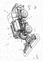
- a self-propelled mower 1 according to the FIGS. 1 and 1a comprises, for example, two fold-out front mowers 2, 3 each with a windrowing unit having a swath unit and at least two, in the illustrated transport position retracted side mowers 4, 5.
- the side mowers 4, 5 are each provided with a swath unit 6, 7.
- the windrow units 6, 7 comprise Schwadb suitable 8, 9, which are pivotally mounted on swing frames 10, 11 on the side mowers 4, 5.
- the side mower 4, 5 are rotatably mounted on telescopic arms 12, 13, so that they are in the transport position shown along the direction of travel F and are arranged in the working position as well as the illustrated front mowers 2, 3 transverse to the direction of travel.
- the self-propelled mower 1 moves in the working position in the mowing direction F. In the transport position, the mower 1 but moves in the opposite direction of travel A, so that during transport advantageously a cab 14 is arranged in front.
- the driver's cab 14 is arranged in the rear region, but can realize a good forward view of the front mowers 2, 3 through the laterally unfolded working units 4, 5, 6, 7.
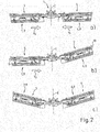
- FIG. 2 a second embodiment of a mower 1 is shown, which is designed as an attachment for a tractor or the like.
- the cultivation takes place for example with the standardized three-point hitch, so that the mower 1 according to FIG. 2 For example, at the rear of the tractor during transport in a raised transport position can be transported.
- FIG. 2a is the "normal" working position of the two side mowers 4, 5 and the downstream or associated swath units 6, 7 and Schwadb sections 8, 9 shown in normal working mode.
- FIG. 3 is the working position of the work units according to FIG. 2a shown schematically in plan view.
- the Schwadbs 8, 9 in the direction of travel F behind the side mowers 4, 5 are arranged so that they directly receive the mowed crop and transport in the central region of the longitudinal central surface E along the conveying directions V1 and V2.
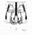
- FIG. 2b shows a working position
- the right working unit or the right side mower 4 is raised together with the right Schwadband 8 and the right swath unit 6 in an intermediate position or in the so-called headland.
- this is for example the first transverse conveyor 6 and the left working unit or the left mower with the left Schwadband 9 and the left Schwadü 7 is in the mowing position.
- the right swath unit 6 according to the invention, the first transverse conveyor unit 6, 8, which has, for example, in this second working mode, a greater conveying speed than the second swath unit 7, 9 in the first working mode.
- the conveying speed of the first windrow unit 6 is slightly increased or accelerated at the moment of lifting or when the lifting is triggered according to an embodiment of the invention.
- FIG 2c is the position of the two side mowers 4, 5 and the windrow units 6, 7 shown, both units are in the so-called headland, that is, in the raised intermediate position.
- This increase in the conveying speed can also be realized temporarily.
- This deflated state can be detected in an advantageous manner and advantageously used to reset the conveying speed or to stop or end the transverse conveying.
- FIG. 5 is a further embodiment of the invention with a tractor 22 shown schematically, to which by means of a hitch 21, a mower M is attached or pulled by this.
- the mower M includes without further illustration in an advantageous manner two side mowers 4, 5, each with a Schwadband 8, 9 roughly comparable to that in FIG. 2 illustrated embodiment. That is also here by means of both Schwadbs 8, 9 transported to the center or to the longitudinal central surface E, the mowed crop. Likewise, a raised headland position or a raised transport position is provided.
- FIG. 5 an already deposited on the field to be machined 20 Querschwad 17 and an already stored and arranged in the viewing direction in front of the tractor or illustrated swath 19 available.
- This swath 19 was generated according to the invention. Accordingly, a swath end 18 of the swath 19 is spaced from the transverse swath 17 in an advantageous manner.
- the increased conveying speed made it possible to quickly empty the swathing strips 8, 9 in such a way that the crop was already deposited on the field 20 before the transverse swath 17.
- a sensor 15 is arranged on the roof of the tractor 22, which can detect an obstacle or crop such as a transverse swath 17 by means of a sensor array 16.
- this is an optical sensor 15 or a camera or like.
- the transverse swath 17 can be detected in an advantageous manner and the swathing can be controlled or controlled.
- the current travel speed and / or location coordinate of the tractor 22 it can be calculated when or where the transverse swath 17 is run over by the mower M.
- the conveying speed of the Schwadbs 8, 9, e.g. automatically increased and / or the mower M are spent in the headland position, so that the mower M and the Schwadbs 8, 9 emptied very quickly or before the transverse swath 17 and in particular raised.
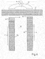
- FIG. 6 a field processing is shown in a transverse swath 17 with a mower 1 according to the invention.
- a field processing is shown in a transverse swath 17 with a mower 1 according to the invention.
- the detection / detection of the transverse swath 17 cf. FIG. 5
- the detection / detection of the transverse swath 17 cf. FIG. 5
- This second conveying speed according to the invention of the front mower 2, 3 and / or the side / rear mower 4, 5 can be carried out advantageously only briefly during the pivoting in / to the headland position or even during the entire time / duration in which the mower , 3, 4, 5 in the headland position or during a headland run 25 (see. FIG. 6 ) located.
- FIG. 6 an advantageous variant of Invention, wherein not only during the entire turn W transverse conveyor units 8, 9 or Schwadb sections 8, 9 according to the invention have the increased second conveying speed or maintained, but alternatively or in combination can according to the invention at the beginning of the mowing process to produce a swath 19b, the increased second conveying speed of the transverse conveyor units 8, 9 or Schwadb supports 8, 9 are provided.
- the increased conveying speed is achieved that a Schad rotating 23 or the swath 19b and a swath section 24 is arranged or stored particularly close / close to the transverse swath 17.
- a particularly advantageous swathing of all swath 18, 17 is possible.
Landscapes
- Life Sciences & Earth Sciences (AREA)
- Environmental Sciences (AREA)
- Harvester Elements (AREA)
Applications Claiming Priority (2)
| Application Number | Priority Date | Filing Date | Title |
|---|---|---|---|
| DE102011100348 | 2011-05-03 | ||
| DE201210004045 DE102012004045A1 (de) | 2011-05-03 | 2012-03-02 | "Erntemaschine mit wenigstens einem Querförderer" |
Publications (1)
| Publication Number | Publication Date |
|---|---|
| EP2520155A1 true EP2520155A1 (fr) | 2012-11-07 |
Family
ID=46177226
Family Applications (1)
| Application Number | Title | Priority Date | Filing Date |
|---|---|---|---|
| EP12166693A Ceased EP2520155A1 (fr) | 2011-05-03 | 2012-05-03 | Moissonneuse avec au moins un convoyeur transversal |
Country Status (2)
| Country | Link |
|---|---|
| EP (1) | EP2520155A1 (fr) |
| DE (1) | DE102012004045A1 (fr) |
Cited By (6)
| Publication number | Priority date | Publication date | Assignee | Title |
|---|---|---|---|---|
| EP3581016A1 (fr) * | 2018-06-15 | 2019-12-18 | CNH Industrial Belgium N.V. | Réglage de la hauteur de rotor de râteau |
| EP3804497A1 (fr) | 2019-10-11 | 2021-04-14 | PÖTTINGER Landtechnik GmbH | Andaineuse ainsi que procédé de commande d'une telle andaineuse |
| US20210282317A1 (en) * | 2020-03-11 | 2021-09-16 | Agco International Gmbh | Agricultural apparatus comprising height sensors, and related methods |
| US20210282319A1 (en) * | 2020-03-11 | 2021-09-16 | Agco International Gmbh | Agricultural apparatus |
| US20210352848A1 (en) * | 2020-05-18 | 2021-11-18 | Claas Saulgau Gmbh | Merger Control Device and Merger |
| US11432464B2 (en) | 2017-06-26 | 2022-09-06 | Kubota Corporation | Harvesting machine with crop detection and harvesting width detection |
Citations (4)
| Publication number | Priority date | Publication date | Assignee | Title |
|---|---|---|---|---|
| EP1068791A1 (fr) | 1999-07-10 | 2001-01-17 | Deere & Company | Faucheuse automotrice munie de convoyeurs |
| EP1155609B1 (fr) | 2000-05-16 | 2004-11-17 | Deere & Company | Dispositif d'andainage |
| DE102005051544A1 (de) | 2005-10-26 | 2007-05-03 | Claas Saulgau Gmbh | Mähmaschine mit einer Schwadeinrichtung |
| US20100223896A1 (en) * | 2009-03-06 | 2010-09-09 | Eick Bronson C | Agricultural Harvester With Accelerated Draper Belt Unload |
-
2012
- 2012-03-02 DE DE201210004045 patent/DE102012004045A1/de not_active Withdrawn
- 2012-05-03 EP EP12166693A patent/EP2520155A1/fr not_active Ceased
Patent Citations (4)
| Publication number | Priority date | Publication date | Assignee | Title |
|---|---|---|---|---|
| EP1068791A1 (fr) | 1999-07-10 | 2001-01-17 | Deere & Company | Faucheuse automotrice munie de convoyeurs |
| EP1155609B1 (fr) | 2000-05-16 | 2004-11-17 | Deere & Company | Dispositif d'andainage |
| DE102005051544A1 (de) | 2005-10-26 | 2007-05-03 | Claas Saulgau Gmbh | Mähmaschine mit einer Schwadeinrichtung |
| US20100223896A1 (en) * | 2009-03-06 | 2010-09-09 | Eick Bronson C | Agricultural Harvester With Accelerated Draper Belt Unload |
Cited By (11)
| Publication number | Priority date | Publication date | Assignee | Title |
|---|---|---|---|---|
| US11432464B2 (en) | 2017-06-26 | 2022-09-06 | Kubota Corporation | Harvesting machine with crop detection and harvesting width detection |
| EP3581016A1 (fr) * | 2018-06-15 | 2019-12-18 | CNH Industrial Belgium N.V. | Réglage de la hauteur de rotor de râteau |
| BE1026368B1 (nl) * | 2018-06-15 | 2020-01-20 | Cnh Ind Belgium Nv | Hoogteregeling van een harkrotor |
| US11889778B2 (en) | 2018-06-15 | 2024-02-06 | Cnh Industrial America Llc | Rake rotor height control |
| EP3804497A1 (fr) | 2019-10-11 | 2021-04-14 | PÖTTINGER Landtechnik GmbH | Andaineuse ainsi que procédé de commande d'une telle andaineuse |
| DE102019127447A1 (de) * | 2019-10-11 | 2021-04-15 | Pöttinger Landtechnik Gmbh | Schwader sowie Verfahren zum Steuern eines solchen Schwaders |
| US20210282317A1 (en) * | 2020-03-11 | 2021-09-16 | Agco International Gmbh | Agricultural apparatus comprising height sensors, and related methods |
| US20210282319A1 (en) * | 2020-03-11 | 2021-09-16 | Agco International Gmbh | Agricultural apparatus |
| US11882790B2 (en) * | 2020-03-11 | 2024-01-30 | Agco International Gmbh | Agricultural apparatus and methods of operating an agricultural apparatus |
| US20210352848A1 (en) * | 2020-05-18 | 2021-11-18 | Claas Saulgau Gmbh | Merger Control Device and Merger |
| US12058961B2 (en) * | 2020-05-18 | 2024-08-13 | Claas Saulgau Gmbh | Merger control device for adjusting conveyor speed or pickup speed as a function of steering angle |
Also Published As
| Publication number | Publication date |
|---|---|
| DE102012004045A1 (de) | 2012-12-06 |
Similar Documents
| Publication | Publication Date | Title |
|---|---|---|
| EP3593620B1 (fr) | Système de récolte | |
| BE1025479B1 (de) | Landwirtschaftliche Erntemaschine zur Bearbeitung und Förderung von Erntegut mit einer Sensoranordnung zur Erkennung von unerwünschten Gefahr- und Inhaltsstoffen im Erntegut | |
| EP1731983B1 (fr) | Machine de travail agricole pourvue d'un dispositif de déversement et d'un capteur de collision | |
| EP3837961B1 (fr) | Combinaison d'un véhicule tracteur et d'un appareil | |
| EP2100495B2 (fr) | Moissonneuse agricole dotée d'une goulotte de transbordement | |
| EP2266383B1 (fr) | Dispositif de commande pour le contrôle du transfert de récoltes agricoles d'une moissonneuse sur un véhicule de transport comportant un récipient de chargement | |
| EP2301323B1 (fr) | Dispositif de surveillance du fonctionnement correct d'un dispositif de réception de produits de récolte | |
| EP2574229B1 (fr) | Moissonneuse agricole automobile dotée d'un accessoire de récolte articulé autour d'un axe vertical | |
| DE102016202628B4 (de) | Sensoranordnung zur Funktionsüberwachung eines Erntevorsatzes | |
| DE102012211001A1 (de) | Anordnung zur Kontrolle einer Austrageinrichtung einer Erntemaschine mit einer selbsttätigen Positionierung in einer Ruhestellung bei nicht möglichen bzw. stattfindendem Überladevorgang | |
| DE102008015277A1 (de) | Verfahren und Vorrichtung zur Lenkung einer zweiten landwirtschaftlichen Maschine, die relativ zu einer ersten landwirtschaftlichen Maschine über ein Feld lenkbar ist | |
| EP1281312B1 (fr) | Dispositif comportant un ramasseur, un convoyeur et moyen de connexion avec un véhicule | |
| EP2510775A1 (fr) | Système et procédé de commande du transfert de récoltes | |
| DE102014105820A1 (de) | Kombination aus einem Zugfahrzeug und einer davon gezogenen Erntemaschine | |
| EP2520155A1 (fr) | Moissonneuse avec au moins un convoyeur transversal | |
| EP2520156B1 (fr) | Moissonneuse avec au moins deux convoyeurs transversaux | |
| EP1796454B1 (fr) | Appareil de recolte, en particulier accessoire de recolte pour des machines de recolte agricoles, servant a cueillir et transporter des cereales | |
| DE102019207984A1 (de) | Erntemaschine mit einem Sensor zur Überwachung des Stoppelbildes | |
| DE102011084288A1 (de) | Selbstfahrende Erntemaschine mit pendelnd aufgehängter Lenkachse und pendelwinkelabhängiger Lenkwinkelbegrenzung | |
| DE102019005662A1 (de) | Auswurfkrümmer für einen Feldhäcksler | |
| BE1026568B1 (de) | Selbstfahrende erntemaschine mit einer überladeeinrichtung | |
| DE102008040217B4 (de) | Zwischen einer Betriebsstellung und einer kompakten Transportstellung verstellbarer Erntevorsatz | |
| EP4490995B1 (fr) | Procédé de fonctionnement d'un attelage agricole | |
| DE202011107270U1 (de) | Erntemaschine mit wenigstens zwei Querförderern | |
| EP3400778B1 (fr) | Procédé de fonctionnement d'une moissonneuse autonome |
Legal Events
| Date | Code | Title | Description |
|---|---|---|---|
| PUAI | Public reference made under article 153(3) epc to a published international application that has entered the european phase |
Free format text: ORIGINAL CODE: 0009012 |
|
| AK | Designated contracting states |
Kind code of ref document: A1 Designated state(s): AL AT BE BG CH CY CZ DE DK EE ES FI FR GB GR HR HU IE IS IT LI LT LU LV MC MK MT NL NO PL PT RO RS SE SI SK SM TR |
|
| AX | Request for extension of the european patent |
Extension state: BA ME |
|
| 17P | Request for examination filed |
Effective date: 20130507 |
|
| 17Q | First examination report despatched |
Effective date: 20160308 |
|
| STAA | Information on the status of an ep patent application or granted ep patent |
Free format text: STATUS: THE APPLICATION HAS BEEN REFUSED |
|
| 18R | Application refused |
Effective date: 20170708 |