EP2520162A1 - Panneau répulsif - Google Patents
Panneau répulsif Download PDFInfo
- Publication number
- EP2520162A1 EP2520162A1 EP11003579A EP11003579A EP2520162A1 EP 2520162 A1 EP2520162 A1 EP 2520162A1 EP 11003579 A EP11003579 A EP 11003579A EP 11003579 A EP11003579 A EP 11003579A EP 2520162 A1 EP2520162 A1 EP 2520162A1
- Authority
- EP
- European Patent Office
- Prior art keywords
- bee
- board
- conduit
- bee hive
- air flow
- Prior art date
- Legal status (The legal status is an assumption and is not a legal conclusion. Google has not performed a legal analysis and makes no representation as to the accuracy of the status listed.)
- Granted
Links
Images

Classifications
-
- A—HUMAN NECESSITIES
- A01—AGRICULTURE; FORESTRY; ANIMAL HUSBANDRY; HUNTING; TRAPPING; FISHING
- A01K—ANIMAL HUSBANDRY; AVICULTURE; APICULTURE; PISCICULTURE; FISHING; REARING OR BREEDING ANIMALS, NOT OTHERWISE PROVIDED FOR; NEW BREEDS OF ANIMALS
- A01K47/00—Beehives
- A01K47/06—Other details of beehives, e.g. ventilating devices, entrances to hives, guards, partitions or bee escapes
-
- A—HUMAN NECESSITIES
- A01—AGRICULTURE; FORESTRY; ANIMAL HUSBANDRY; HUNTING; TRAPPING; FISHING
- A01K—ANIMAL HUSBANDRY; AVICULTURE; APICULTURE; PISCICULTURE; FISHING; REARING OR BREEDING ANIMALS, NOT OTHERWISE PROVIDED FOR; NEW BREEDS OF ANIMALS
- A01K51/00—Appliances for treating beehives or parts thereof, e.g. for cleaning or disinfecting
Definitions
- the present invention relates to a device and a method for expelling bees from a bee hive, in particular, for expelling honey bees from a bee hive containing bee frames.
- the beekeeper In order to collect honey from a bee hive, the beekeeper needs to remove the frames containing the honey from the bee hive. As the frames are usually populated by bees, it is necessary to first remove the bees from the frames. This is usually done by removing a top cover of the bee hive and taking out the frames. The frames are then shaken in order to remove the bees from the frames. This, however, requires a long time and, moreover, excites the bees and causes the death of many of them. In addition, the beekeeper is often stung during this procedure.
- the present invention in particular, provides a device according to claim 1, a bee hive according to claim 13 and a method according to claim 15.
- the present invention provides a device for expelling bees from a bee hive, the bee hive having a portion containing at least one bee frame.
- the device comprises:
- the device of the present invention provides the opportunity to expel the bees from the bee hive before opening the bee hive.
- the device may be put on a bee hive and is adapted to provide an air flow from top to bottom through the portion of the bee hive containing the at least one frame.
- the device may be configured as a top cover for the bee hive.
- the bees inside the bee hive are driven by the air flow towards the bottom of the bee hive, where an entrance opening for bees is present in the bee hive.
- the bees are thus gently removed from the frames and expelled from the bee hive. After operation of the device, the majority of the bees has left the hive and the beekeeper may safely remove the frames.
- the air flow directed into portion of the bee hive is from top to bottom.
- the air flow may be directed to pass over both sides of each of the at least one bee frame.
- both sides refers to the sides of the frames into which the bees build their combs.
- the air flow may be directed as to pass through all gaps in a cross section of the portion of the bee hive not taken by the at least one bee frame.
- the inlet is for connecting to a blower.
- the blower may comprise a manually operated or an electric blower as specified below.
- the device is not adapted to control a temperature or humidity of the air flow into the bee hive.
- the device is not adapted to heat up or cool the air.
- no substances are added to the air flow for affecting the bees.
- no smoke is added to the air flow.
- pollution of the bees and the honey is avoided.
- no bee repellent chemicals substance is added.
- the outlet slits may extend uniformly. Alternatively or additionally, they may comprise one or more intermitting bridges. This renders the outlet slits mechanically more stable, in particular, if the conduit system comprises tubes. Alternative or additionally, the outlet slits may be tapered towards their ends. This facilitates control of speed at which the air flow leaves through the outlet slits.
- the board may, in particular, be made of wood, plastic or metal.
- the board is made of plywood.
- the bottom side of the board may have a length of between 30 cm and 100 cm, in particular between 40 cm and 65 cm and, preferably between 45 cm and 55 cm.
- the bottom side may have a width of between 20 cm and 60 cm, in particular between 30 cm and 50 cm, and preferably between 35 cm and 45 cm.
- the device further comprises one, two or four handles attached to the board. This facilitates moving the device.
- the conduit system further comprises between 2 and 20, in particular between 4 and 11 and preferably between 6 and 10 additional outlet slits for directing at least a part of the air flow into said portion of the bee hive.
- the number of outlet slits is increased for a more homogeneous distribution of the air flow directed into the portion of the bee hive.
- the number of branch conduits may be equivalent to the number of bee frames in the bee hive plus one.
- there is one outlet slit per gap including the outermost gaps between a respective one of the frames and an adjacent side wall of the bee hive.
- the air flow passes over both sides of every frame in the bee hive.
- the device may comprise two outlet slits per frame of the bee hive.
- each outlet slit may be arranged, such that the air flow is directed towards one side of a frame.
- the conduit system comprises a main air conduit having said inlet, and a set of branch conduits, each branch conduit having at least one of said outlet slits, the main air conduit being connected to the branch conduits.
- the main air conduit is used to distribute the air flow received via the inlet to the set of branch conduits.
- the branch conduits then distribute the air flow into the portion of the bee hive.
- the outlet slits may be parallel to a longitudinal axis of the branch conduits.
- the main air conduit and/or the branch conduits may, in particular, have a diameter of between 20 mm and 100 mm, in particular between 30 mm and 80 mm and preferably between 40 mm and 60 mm.
- the main air conduit may have a larger diameter than the branch conduits.
- the branch conduits and/or outlet slits may be tapered. This allows for a more homogenous pressure distribution along the branch conduits.
- each of said outlet slits may extend over a length of the respective branch conduit.
- the length of the branch conduit is efficiently used to provide a maximum longitudinal extension of the air flow.
- each branch conduit has a first and a second end, the branch conduits being connected to the main air conduit at their first ends or at a center between their first and second ends.
- the main air conduit may conveniently be located at one end of the board.
- the branch conduits may be connected to the main air conduit near the center between their first and second ends. This embodiment leads to a symmetrical air pressure distribution inside the branch conduits.
- the branch conduits extend transverse, in particular, perpendicular to the main air conduit.
- the connection length of the main air conduit between adjacent branch conduits is minimized, such that less air pressure is needed at the inlet of the main air conduit to supply air to all of the branch conduits.
- the conduit system is at least partially integrated into the board.
- the main air conduit and/or the branch conduits may be integrated into the board. This embodiment leads to a compact arrangement of the device minimizing a risk of the device being damaged.
- the conduit system is at least partially attached to the bottom side of the board.
- the main air conduit and/or the branch conduits may be attached to the bottom side of the board.
- the conduit may be easily arranged at the bottom side of the board.
- the conduit may be glued to the bottom side of the board.
- the conduit system comprises at least one tube.
- the tube may, e.g. comprise a plastic tube. Tubes are usually readily available in areas in which bee hives are used. Moreover, a standard knife may be used to easily provide outlet slits.
- the main air conduit and/or the branch conduits may comprise at least one tube.
- the inlet is arranged at a top side or a lateral side of the board. This allows for easy access to the inlet from outside the bee hive during operation.
- the inlet of the main air conduit may be arranged at the bottom side of the board. This is preferred if a blower adapted to be operated inside the bee hive is connected to the inlet as is provided in an embodiment of the present invention.
- the device further has an outlet arranged at a top side or a lateral side of the board.
- several devices according to the present invention may be used connected in series.
- only one blower is needed for operation of more than one device. The air is blown into one of the boards by a blower via the inlet, passes through that board and leaves via the outlet. Thus, an airflow through a series of devices is caused.
- the inlet and/or outlet of the main air conduit may comprise connecting means for connecting to a blower.
- the connecting means may, e.g. comprise a thread, a screw, locking means, latching means and/or clamping means.
- the outlet slits have a width of between 3 mm and 20 mm, in particular between 5 mm and 15 mm and, preferably, between 8 mm and 12 mm.
- the outlet slits Having a width in that range, the outlet slits generate a wide enough airflow inside the bee hive for reaching most bees. Moreover, the outlet slits are still narrow enough such that the pressure inside the main air conduit and the branch conduits does not fall off too quickly, such that the airflow reaches the end of the conduits.
- adjacent outlet slits are spaced at a distance of between 10 mm and 100 mm, in particular between 15 mm and 60 mm and, preferably between 25 mm and 40 mm. This leads to an evenly distributed air flow inside the bee hive, passing both sides of the frames.
- the device further comprises protection means arranged at the outlet slits for preventing the bees entering the conduit system.
- the protection means may comprise, e.g. a mesh, a net or wires. Openings in the protection means may be dimensioned such that bees cannot pass through. This prevents bees from entering the branch conduits and blocking the conduits.
- the outlet slits extend parallel to each other. This is preferred as the device provides a symmetric air flow distribution in the bee hive.
- the outlet slits extend parallel to the frames inside the bee hive to fit with the actual space between frames. This leads to a more symmetric air flow distribution within each gap between each two adjacent bee frames.
- the device further comprises a manual blower connected to the inlet.
- a manual blower rather than an electric blower provides a better control of the air flow intensity.
- the rate of air blowing in may be controlled depending on an observed reaction of the bees.
- the device comprises an electric blower connected to the inlet. This is, in particular, preferred if the device has an outlet for connecting to an additional device.
- An electric blower allows higher rates of air flow blowing into the inlet.
- the electric blower may, in particular, be adapted to blow in air into the inlets of more than one device connected in series or in parallel.
- the present invention provides a bee hive comprising the device of the aforementioned type.
- the bee hive may comprise the device of the aforementioned type as a cover with the bee hive further comprising an entrance opening for the bees arranged at a bottom thereof.
- the device provides an airflow inside the bee hive which extends from the top of the bee hive to the bottom thereof.
- the bees are driven from inside the bee hive towards the entrance opening, where they leave the hive.
- the bee hive further has at least one bee frame and at least one of said at least two outlet slits of the device is further arranged for directing at least a part of the air flow to extend over a side of the bee frame.
- two of the at least two outlet slits of the device are arranged for directing at least a part of the air flow to extend over a respective side of the bee frame.
- the outlet slits may be parallel to the at least one bee frame.
- two of the at least two outlet slits may be adjacent to the at least one bee frame, with one of the outlet slits on both sides of the frame, respectively.
- the present invention provides a method for repelling bees from a bee hive with at least one bee frame, in particular, using the device of the aforementioned type, the method comprising: providing an air flow from top to bottom inside the bee hive, the air flow extending over a side of the at least one frame.
- the air flow extends over both sides to the at least one frame.
- the air flow passes over a side of the frame for the bees to build their honey combs into.
- the air flow contacts the bees on the sides of the frame and drives them downwards.
- the air flow may be directed to fill an entirety of gaps in a horizontal cross section of the bee hive.
- the strength of the air flow may be configured to drive the bees. This is in contrast to a soft air flow for mere ventilation of the bee hive, which is usually much weaker.
- the method comprises:
- step c) may further comprise operating the blower for between 60 s and 600 s, in particular between 120 s and 480 s and preferably between 180 s and 360 s.
- the method may further comprise the step of
- the method may use at least two devices of the aforementioned type and further comprise connecting the main air conduits of the at least two devices together.
- the connection may, in particular, be in parallel or in series.
- the method may comprise connecting the main air conduits of two or more devices of the present invention with one blower.
- Figure 1 shows a device according to a first embodiment of the present invention in top view.
- the device comprises a rectangular board 10. At one end, the board is equipped with two handles 12. The handles 12 are parallel to each other.
- Figure 2 shows the device of figure 1 in bottom view.
- bottom side 13 of the board 10 is shown.
- Attached to the bottom side 13 of the board 10 is a main air conduit 21 which extends parallel to an edge of the board 10.
- the main air conduit 21 neighbors the edge of the board 10 where the handles 12 are attached.
- the main air conduit 21 is a plastic tube attached to the bottom side 13.
- the main air conduit 21 comprises an inlet 23.
- the inlet 23 is arranged at an edge of the board 10.
- the inlet 23 is arranged at a first end of the main air conduit 21.
- a second end of the main air conduit 21 opposite the end with the inlet 23 is closed.
- the device of figure 2 further comprises nine branch conduits 22.
- the branch conduits 22 extend parallel to each other. In the embodiment of figure 2 , adjacent branch conduits 22 are arranged at different distances. This is preferred if the frames inside the bee hive are not evenly spaced, but have different distances between each other.
- the branch conduits 22 are plastic tubes attached to the bottom side 13 of the board 10. In more detail, the branch conduits 22 are glued to the bottom side 13.
- each branch conduit 22 has identical lengths. Moreover, each branch conduit 22 has a first end 26 which is connected to the main air conduit 21. Each branch conduit 22 further has a second end opposite the first end 26 which is closed. Moreover, each branch conduit 22 has an outlet slit (not shown) extending between the first end 26 and the second end thereof. Moreover, the outlet slits of each branch conduit 22 extends along a longitudinal axis of the branch conduit. The outlet slits extend over a length of the frames in the bee hive.
- the device is not adapted to increase the temperature of air blown into the inlet of the main air conduit before the air is blown into the bee hive. Moreover, the device is not adapted to increase a humidity of the air blown into the bee hive.
- FIG. 3 shows a device according to a second embodiment of the present invention in bottom view.
- the device comprises a board 10' with two handles 12 attached at a side thereof.
- the device comprises a main air conduit 21'.
- the main air conduit 21' extends from one edge of the board 10' to an opposite end thereof.
- the main air conduit 21' has a first and a second end, generally indicated by reference numeral 23.
- Each of the first and second ends 23 may interchangeably be used as an inlet or an outlet.
- a blower may be connected to one of the openings 23 acting as an inlet, while a main air conduit of a second device may be connected to the other opening 23 thus acting as an outlet.
- the device of figure 3 further has six branch conduits 22 extending parallel to each other and having the same length.
- the branch conduits 22 have first ends 26' and a second ends.
- the branch conduits 22 are connected to the main air conduit 21' at their first ends 26'.
- the branch conduits 22 are evenly spaced.
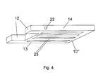
- Figure 4 shows a perspective view of a device according to a third embodiment of the present invention.
- the device of figure 4 comprises a board 10" with two handles 12 arranged at one lateral side thereof.
- the device has four branch conduits being incorporated into the board 10".
- the branch conduits have outlet slits 26 arranged at a bottom side 13 of the board 10".
- the branch conduits are integrated into the board 10", such that no additional elements reach out below the bottom board, thus preventing damage of the device.
- the device of figure 4 has a main air conduit integrated into the board 10".
- the main air conduit has an inlet 23 arranged at a lateral side 14 of the board.
Landscapes
- Life Sciences & Earth Sciences (AREA)
- Environmental Sciences (AREA)
- Animal Husbandry (AREA)
- Biodiversity & Conservation Biology (AREA)
- Catching Or Destruction (AREA)
- Feed For Specific Animals (AREA)
Priority Applications (4)
| Application Number | Priority Date | Filing Date | Title |
|---|---|---|---|
| EP11003579.7A EP2520162B1 (fr) | 2011-05-02 | 2011-05-02 | Panneau répulsif |
| US14/008,578 US8998675B2 (en) | 2011-05-02 | 2012-04-23 | Repellent board |
| PCT/EP2012/001735 WO2012150006A1 (fr) | 2011-05-02 | 2012-04-23 | Planche répulsive |
| SA112330475A SA112330475B1 (ar) | 2011-05-02 | 2012-04-23 | أداة لطرد النحل من خلية نحل |
Applications Claiming Priority (1)
| Application Number | Priority Date | Filing Date | Title |
|---|---|---|---|
| EP11003579.7A EP2520162B1 (fr) | 2011-05-02 | 2011-05-02 | Panneau répulsif |
Publications (2)
| Publication Number | Publication Date |
|---|---|
| EP2520162A1 true EP2520162A1 (fr) | 2012-11-07 |
| EP2520162B1 EP2520162B1 (fr) | 2013-09-04 |
Family
ID=44652099
Family Applications (1)
| Application Number | Title | Priority Date | Filing Date |
|---|---|---|---|
| EP11003579.7A Not-in-force EP2520162B1 (fr) | 2011-05-02 | 2011-05-02 | Panneau répulsif |
Country Status (4)
| Country | Link |
|---|---|
| US (1) | US8998675B2 (fr) |
| EP (1) | EP2520162B1 (fr) |
| SA (1) | SA112330475B1 (fr) |
| WO (1) | WO2012150006A1 (fr) |
Families Citing this family (2)
| Publication number | Priority date | Publication date | Assignee | Title |
|---|---|---|---|---|
| US20140329437A1 (en) * | 2013-05-05 | 2014-11-06 | Horacio Acevedo | A method and apparatus for treating a bees nest |
| CN111919793B (zh) * | 2020-08-31 | 2024-11-22 | 尚国强 | 一种防坠脾生物巢础 |
Citations (2)
| Publication number | Priority date | Publication date | Assignee | Title |
|---|---|---|---|---|
| US3394426A (en) * | 1967-02-16 | 1968-07-30 | Robert J. Knox | Honey hive and comb frame cleaning apparatus |
| HU187967B (hu) * | 1983-08-30 | 1986-03-28 | Tokar,Janos,Hu | Szerkezet méheknek kaptár-keretről történő eltávolítására |
Family Cites Families (2)
| Publication number | Priority date | Publication date | Assignee | Title |
|---|---|---|---|---|
| US773571A (en) * | 1904-05-14 | 1904-11-01 | Oscar F Kerr | Beehive. |
| US2261298A (en) * | 1939-11-27 | 1941-11-04 | William D Terpany | Beehive |
-
2011
- 2011-05-02 EP EP11003579.7A patent/EP2520162B1/fr not_active Not-in-force
-
2012
- 2012-04-23 WO PCT/EP2012/001735 patent/WO2012150006A1/fr not_active Ceased
- 2012-04-23 US US14/008,578 patent/US8998675B2/en not_active Expired - Fee Related
- 2012-04-23 SA SA112330475A patent/SA112330475B1/ar unknown
Patent Citations (2)
| Publication number | Priority date | Publication date | Assignee | Title |
|---|---|---|---|---|
| US3394426A (en) * | 1967-02-16 | 1968-07-30 | Robert J. Knox | Honey hive and comb frame cleaning apparatus |
| HU187967B (hu) * | 1983-08-30 | 1986-03-28 | Tokar,Janos,Hu | Szerkezet méheknek kaptár-keretről történő eltávolítására |
Also Published As
| Publication number | Publication date |
|---|---|
| WO2012150006A1 (fr) | 2012-11-08 |
| EP2520162B1 (fr) | 2013-09-04 |
| US8998675B2 (en) | 2015-04-07 |
| SA112330475B1 (ar) | 2015-09-15 |
| US20140242875A1 (en) | 2014-08-28 |
Similar Documents
| Publication | Publication Date | Title |
|---|---|---|
| EP3726975B1 (fr) | Dispositif de transport d'insectes vivants | |
| AU2007254636B2 (en) | Treatment fluid dispenser for control of mites | |
| US20220132812A1 (en) | System for a Beehive | |
| IL274613B1 (en) | Automatic beehives | |
| US20090068926A1 (en) | Assembly for capturing bees | |
| US11985960B2 (en) | Live insects transport device | |
| WO2016089980A1 (fr) | Guide de formation de rayon pour placement entre des cadres de ruche | |
| US12161090B2 (en) | Structures and methods for removal of frames from beehives and a bee-gate | |
| CN107047377B (zh) | 可改善蜜蜂环境的蜂箱 | |
| EP2520162B1 (fr) | Panneau répulsif | |
| US20140262166A1 (en) | Waste Heat Recovery Apparatus for a Livestock Poultry Barn | |
| WO2011094201A1 (fr) | Systeme de collecte d'abeilles melliferes | |
| EP0129504A1 (fr) | Dispositif pour la capture d'insectes hyménoptères, en particulier d'abeilles, et pour le peuplement des boîtes de copulation pour abeilles | |
| KR20170053978A (ko) | 탈착식 꿀벌 교미벌통 | |
| EP2250880B1 (fr) | Dispositif destiné à lutter contre les acariens attaquant les abeilles | |
| WO2016151468A1 (fr) | Procédé et appareil destinés au traitement de ruches | |
| KR101339952B1 (ko) | 공기이송로를 포함하는 벌통 패널 및 벌통 | |
| RO128080B1 (ro) | Stup multifuncţional cu protecţie împotriva varozei | |
| WO2004098276A3 (fr) | Systeme thermique pour la lutte contre les acariens et autres ameliorations dans une ruche | |
| KR20130003329A (ko) | 에어커텐을 구비한 냄새차단 개별환기 실험동물 사육장치 | |
| US20250064028A1 (en) | Device, system and method for thermal treatment of pollinating insects | |
| RU2831274C1 (ru) | Устройство многофункциональное для термической обработки в пчеловодстве | |
| KR101937631B1 (ko) | 통기망이 형성된 벌통 및 이를 구비한 캠핑 트레일러 | |
| KR102548373B1 (ko) | 양봉용 벌통의 벌 탈리장치 | |
| KR20260063361A (ko) | 실내 양육부를 갖는 벌양육장치 |
Legal Events
| Date | Code | Title | Description |
|---|---|---|---|
| PUAI | Public reference made under article 153(3) epc to a published international application that has entered the european phase |
Free format text: ORIGINAL CODE: 0009012 |
|
| AK | Designated contracting states |
Kind code of ref document: A1 Designated state(s): AL AT BE BG CH CY CZ DE DK EE ES FI FR GB GR HR HU IE IS IT LI LT LU LV MC MK MT NL NO PL PT RO RS SE SI SK SM TR |
|
| AX | Request for extension of the european patent |
Extension state: BA ME |
|
| 17P | Request for examination filed |
Effective date: 20130408 |
|
| RIC1 | Information provided on ipc code assigned before grant |
Ipc: A01K 47/06 20060101AFI20130430BHEP Ipc: A01K 51/00 20060101ALI20130430BHEP |
|
| GRAP | Despatch of communication of intention to grant a patent |
Free format text: ORIGINAL CODE: EPIDOSNIGR1 |
|
| INTG | Intention to grant announced |
Effective date: 20130607 |
|
| RIN1 | Information on inventor provided before grant (corrected) |
Inventor name: ABOU-SHAARA, HOSSAM, FARAG, IBRAHIM Inventor name: AL-KHAZIM AL GHAMDI, AHMAD, PROF., DR. |
|
| GRAS | Grant fee paid |
Free format text: ORIGINAL CODE: EPIDOSNIGR3 |
|
| GRAA | (expected) grant |
Free format text: ORIGINAL CODE: 0009210 |
|
| AK | Designated contracting states |
Kind code of ref document: B1 Designated state(s): AL AT BE BG CH CY CZ DE DK EE ES FI FR GB GR HR HU IE IS IT LI LT LU LV MC MK MT NL NO PL PT RO RS SE SI SK SM TR |
|
| REG | Reference to a national code |
Ref country code: GB Ref legal event code: FG4D |
|
| REG | Reference to a national code |
Ref country code: CH Ref legal event code: EP |
|
| REG | Reference to a national code |
Ref country code: AT Ref legal event code: REF Ref document number: 629957 Country of ref document: AT Kind code of ref document: T Effective date: 20130915 |
|
| REG | Reference to a national code |
Ref country code: IE Ref legal event code: FG4D |
|
| REG | Reference to a national code |
Ref country code: DE Ref legal event code: R096 Ref document number: 602011002863 Country of ref document: DE Effective date: 20131031 |
|
| REG | Reference to a national code |
Ref country code: AT Ref legal event code: MK05 Ref document number: 629957 Country of ref document: AT Kind code of ref document: T Effective date: 20130904 |
|
| REG | Reference to a national code |
Ref country code: NL Ref legal event code: VDEP Effective date: 20130904 |
|
| PG25 | Lapsed in a contracting state [announced via postgrant information from national office to epo] |
Ref country code: CY Free format text: LAPSE BECAUSE OF FAILURE TO SUBMIT A TRANSLATION OF THE DESCRIPTION OR TO PAY THE FEE WITHIN THE PRESCRIBED TIME-LIMIT Effective date: 20130918 Ref country code: HR Free format text: LAPSE BECAUSE OF FAILURE TO SUBMIT A TRANSLATION OF THE DESCRIPTION OR TO PAY THE FEE WITHIN THE PRESCRIBED TIME-LIMIT Effective date: 20130904 Ref country code: LT Free format text: LAPSE BECAUSE OF FAILURE TO SUBMIT A TRANSLATION OF THE DESCRIPTION OR TO PAY THE FEE WITHIN THE PRESCRIBED TIME-LIMIT Effective date: 20130904 Ref country code: NO Free format text: LAPSE BECAUSE OF FAILURE TO SUBMIT A TRANSLATION OF THE DESCRIPTION OR TO PAY THE FEE WITHIN THE PRESCRIBED TIME-LIMIT Effective date: 20131204 Ref country code: AT Free format text: LAPSE BECAUSE OF FAILURE TO SUBMIT A TRANSLATION OF THE DESCRIPTION OR TO PAY THE FEE WITHIN THE PRESCRIBED TIME-LIMIT Effective date: 20130904 Ref country code: SE Free format text: LAPSE BECAUSE OF FAILURE TO SUBMIT A TRANSLATION OF THE DESCRIPTION OR TO PAY THE FEE WITHIN THE PRESCRIBED TIME-LIMIT Effective date: 20130904 |
|
| REG | Reference to a national code |
Ref country code: NL Ref legal event code: VDEP Effective date: 20130904 |
|
| REG | Reference to a national code |
Ref country code: LT Ref legal event code: MG4D |
|
| PG25 | Lapsed in a contracting state [announced via postgrant information from national office to epo] |
Ref country code: GR Free format text: LAPSE BECAUSE OF FAILURE TO SUBMIT A TRANSLATION OF THE DESCRIPTION OR TO PAY THE FEE WITHIN THE PRESCRIBED TIME-LIMIT Effective date: 20131205 Ref country code: FI Free format text: LAPSE BECAUSE OF FAILURE TO SUBMIT A TRANSLATION OF THE DESCRIPTION OR TO PAY THE FEE WITHIN THE PRESCRIBED TIME-LIMIT Effective date: 20130904 Ref country code: PL Free format text: LAPSE BECAUSE OF FAILURE TO SUBMIT A TRANSLATION OF THE DESCRIPTION OR TO PAY THE FEE WITHIN THE PRESCRIBED TIME-LIMIT Effective date: 20130904 Ref country code: LV Free format text: LAPSE BECAUSE OF FAILURE TO SUBMIT A TRANSLATION OF THE DESCRIPTION OR TO PAY THE FEE WITHIN THE PRESCRIBED TIME-LIMIT Effective date: 20130904 |
|
| PG25 | Lapsed in a contracting state [announced via postgrant information from national office to epo] |
Ref country code: CY Free format text: LAPSE BECAUSE OF FAILURE TO SUBMIT A TRANSLATION OF THE DESCRIPTION OR TO PAY THE FEE WITHIN THE PRESCRIBED TIME-LIMIT Effective date: 20130904 Ref country code: BE Free format text: LAPSE BECAUSE OF FAILURE TO SUBMIT A TRANSLATION OF THE DESCRIPTION OR TO PAY THE FEE WITHIN THE PRESCRIBED TIME-LIMIT Effective date: 20130904 |
|
| PG25 | Lapsed in a contracting state [announced via postgrant information from national office to epo] |
Ref country code: IS Free format text: LAPSE BECAUSE OF FAILURE TO SUBMIT A TRANSLATION OF THE DESCRIPTION OR TO PAY THE FEE WITHIN THE PRESCRIBED TIME-LIMIT Effective date: 20140104 Ref country code: NL Free format text: LAPSE BECAUSE OF FAILURE TO SUBMIT A TRANSLATION OF THE DESCRIPTION OR TO PAY THE FEE WITHIN THE PRESCRIBED TIME-LIMIT Effective date: 20130904 Ref country code: RO Free format text: LAPSE BECAUSE OF FAILURE TO SUBMIT A TRANSLATION OF THE DESCRIPTION OR TO PAY THE FEE WITHIN THE PRESCRIBED TIME-LIMIT Effective date: 20130904 Ref country code: CZ Free format text: LAPSE BECAUSE OF FAILURE TO SUBMIT A TRANSLATION OF THE DESCRIPTION OR TO PAY THE FEE WITHIN THE PRESCRIBED TIME-LIMIT Effective date: 20130904 Ref country code: SK Free format text: LAPSE BECAUSE OF FAILURE TO SUBMIT A TRANSLATION OF THE DESCRIPTION OR TO PAY THE FEE WITHIN THE PRESCRIBED TIME-LIMIT Effective date: 20130904 Ref country code: EE Free format text: LAPSE BECAUSE OF FAILURE TO SUBMIT A TRANSLATION OF THE DESCRIPTION OR TO PAY THE FEE WITHIN THE PRESCRIBED TIME-LIMIT Effective date: 20130904 |
|
| PG25 | Lapsed in a contracting state [announced via postgrant information from national office to epo] |
Ref country code: ES Free format text: LAPSE BECAUSE OF FAILURE TO SUBMIT A TRANSLATION OF THE DESCRIPTION OR TO PAY THE FEE WITHIN THE PRESCRIBED TIME-LIMIT Effective date: 20130904 |
|
| REG | Reference to a national code |
Ref country code: DE Ref legal event code: R097 Ref document number: 602011002863 Country of ref document: DE |
|
| PG25 | Lapsed in a contracting state [announced via postgrant information from national office to epo] |
Ref country code: PT Free format text: LAPSE BECAUSE OF FAILURE TO SUBMIT A TRANSLATION OF THE DESCRIPTION OR TO PAY THE FEE WITHIN THE PRESCRIBED TIME-LIMIT Effective date: 20140106 |
|
| PLBE | No opposition filed within time limit |
Free format text: ORIGINAL CODE: 0009261 |
|
| STAA | Information on the status of an ep patent application or granted ep patent |
Free format text: STATUS: NO OPPOSITION FILED WITHIN TIME LIMIT |
|
| 26N | No opposition filed |
Effective date: 20140605 |
|
| PG25 | Lapsed in a contracting state [announced via postgrant information from national office to epo] |
Ref country code: IT Free format text: LAPSE BECAUSE OF FAILURE TO SUBMIT A TRANSLATION OF THE DESCRIPTION OR TO PAY THE FEE WITHIN THE PRESCRIBED TIME-LIMIT Effective date: 20130904 |
|
| REG | Reference to a national code |
Ref country code: DE Ref legal event code: R097 Ref document number: 602011002863 Country of ref document: DE Effective date: 20140605 |
|
| PG25 | Lapsed in a contracting state [announced via postgrant information from national office to epo] |
Ref country code: DK Free format text: LAPSE BECAUSE OF FAILURE TO SUBMIT A TRANSLATION OF THE DESCRIPTION OR TO PAY THE FEE WITHIN THE PRESCRIBED TIME-LIMIT Effective date: 20130904 |
|
| PG25 | Lapsed in a contracting state [announced via postgrant information from national office to epo] |
Ref country code: LU Free format text: LAPSE BECAUSE OF FAILURE TO SUBMIT A TRANSLATION OF THE DESCRIPTION OR TO PAY THE FEE WITHIN THE PRESCRIBED TIME-LIMIT Effective date: 20140502 |
|
| REG | Reference to a national code |
Ref country code: CH Ref legal event code: PL |
|
| PG25 | Lapsed in a contracting state [announced via postgrant information from national office to epo] |
Ref country code: MC Free format text: LAPSE BECAUSE OF FAILURE TO SUBMIT A TRANSLATION OF THE DESCRIPTION OR TO PAY THE FEE WITHIN THE PRESCRIBED TIME-LIMIT Effective date: 20130904 Ref country code: CH Free format text: LAPSE BECAUSE OF NON-PAYMENT OF DUE FEES Effective date: 20140531 Ref country code: LI Free format text: LAPSE BECAUSE OF NON-PAYMENT OF DUE FEES Effective date: 20140531 |
|
| REG | Reference to a national code |
Ref country code: IE Ref legal event code: MM4A |
|
| PG25 | Lapsed in a contracting state [announced via postgrant information from national office to epo] |
Ref country code: IE Free format text: LAPSE BECAUSE OF NON-PAYMENT OF DUE FEES Effective date: 20140502 |
|
| PG25 | Lapsed in a contracting state [announced via postgrant information from national office to epo] |
Ref country code: MT Free format text: LAPSE BECAUSE OF FAILURE TO SUBMIT A TRANSLATION OF THE DESCRIPTION OR TO PAY THE FEE WITHIN THE PRESCRIBED TIME-LIMIT Effective date: 20130904 |
|
| REG | Reference to a national code |
Ref country code: FR Ref legal event code: PLFP Year of fee payment: 6 |
|
| PG25 | Lapsed in a contracting state [announced via postgrant information from national office to epo] |
Ref country code: SM Free format text: LAPSE BECAUSE OF FAILURE TO SUBMIT A TRANSLATION OF THE DESCRIPTION OR TO PAY THE FEE WITHIN THE PRESCRIBED TIME-LIMIT Effective date: 20130904 |
|
| PG25 | Lapsed in a contracting state [announced via postgrant information from national office to epo] |
Ref country code: BG Free format text: LAPSE BECAUSE OF FAILURE TO SUBMIT A TRANSLATION OF THE DESCRIPTION OR TO PAY THE FEE WITHIN THE PRESCRIBED TIME-LIMIT Effective date: 20130904 Ref country code: RS Free format text: LAPSE BECAUSE OF NON-PAYMENT OF DUE FEES Effective date: 20130904 |
|
| PG25 | Lapsed in a contracting state [announced via postgrant information from national office to epo] |
Ref country code: SI Free format text: LAPSE BECAUSE OF FAILURE TO SUBMIT A TRANSLATION OF THE DESCRIPTION OR TO PAY THE FEE WITHIN THE PRESCRIBED TIME-LIMIT Effective date: 20130904 Ref country code: TR Free format text: LAPSE BECAUSE OF FAILURE TO SUBMIT A TRANSLATION OF THE DESCRIPTION OR TO PAY THE FEE WITHIN THE PRESCRIBED TIME-LIMIT Effective date: 20130904 Ref country code: HU Free format text: LAPSE BECAUSE OF FAILURE TO SUBMIT A TRANSLATION OF THE DESCRIPTION OR TO PAY THE FEE WITHIN THE PRESCRIBED TIME-LIMIT; INVALID AB INITIO Effective date: 20110502 |
|
| REG | Reference to a national code |
Ref country code: FR Ref legal event code: PLFP Year of fee payment: 7 |
|
| PG25 | Lapsed in a contracting state [announced via postgrant information from national office to epo] |
Ref country code: MK Free format text: LAPSE BECAUSE OF FAILURE TO SUBMIT A TRANSLATION OF THE DESCRIPTION OR TO PAY THE FEE WITHIN THE PRESCRIBED TIME-LIMIT Effective date: 20130904 |
|
| REG | Reference to a national code |
Ref country code: FR Ref legal event code: PLFP Year of fee payment: 8 |
|
| PG25 | Lapsed in a contracting state [announced via postgrant information from national office to epo] |
Ref country code: AL Free format text: LAPSE BECAUSE OF FAILURE TO SUBMIT A TRANSLATION OF THE DESCRIPTION OR TO PAY THE FEE WITHIN THE PRESCRIBED TIME-LIMIT Effective date: 20130904 |
|
| PGFP | Annual fee paid to national office [announced via postgrant information from national office to epo] |
Ref country code: DE Payment date: 20181030 Year of fee payment: 8 |
|
| PGFP | Annual fee paid to national office [announced via postgrant information from national office to epo] |
Ref country code: FR Payment date: 20181030 Year of fee payment: 8 Ref country code: GB Payment date: 20181030 Year of fee payment: 8 |
|
| REG | Reference to a national code |
Ref country code: DE Ref legal event code: R119 Ref document number: 602011002863 Country of ref document: DE |
|
| GBPC | Gb: european patent ceased through non-payment of renewal fee |
Effective date: 20190502 |
|
| PG25 | Lapsed in a contracting state [announced via postgrant information from national office to epo] |
Ref country code: DE Free format text: LAPSE BECAUSE OF NON-PAYMENT OF DUE FEES Effective date: 20191203 Ref country code: GB Free format text: LAPSE BECAUSE OF NON-PAYMENT OF DUE FEES Effective date: 20190502 |
|
| PG25 | Lapsed in a contracting state [announced via postgrant information from national office to epo] |
Ref country code: FR Free format text: LAPSE BECAUSE OF NON-PAYMENT OF DUE FEES Effective date: 20190531 |