EP2520211B1 - Dispositif d'endoscope a fluorescence - Google Patents
Dispositif d'endoscope a fluorescence Download PDFInfo
- Publication number
- EP2520211B1 EP2520211B1 EP11742110.7A EP11742110A EP2520211B1 EP 2520211 B1 EP2520211 B1 EP 2520211B1 EP 11742110 A EP11742110 A EP 11742110A EP 2520211 B1 EP2520211 B1 EP 2520211B1
- Authority
- EP
- European Patent Office
- Prior art keywords
- fluorescence
- image
- threshold
- light
- gradation value
- Prior art date
- Legal status (The legal status is an assumption and is not a legal conclusion. Google has not performed a legal analysis and makes no representation as to the accuracy of the status listed.)
- Not-in-force
Links
- 238000002073 fluorescence micrograph Methods 0.000 claims description 189
- 230000005284 excitation Effects 0.000 claims description 40
- 239000000284 extract Substances 0.000 claims description 11
- 238000005286 illumination Methods 0.000 claims description 11
- 230000004048 modification Effects 0.000 description 16
- 238000012986 modification Methods 0.000 description 16
- 238000010586 diagram Methods 0.000 description 11
- 210000004204 blood vessel Anatomy 0.000 description 7
- 239000003795 chemical substances by application Substances 0.000 description 5
- 239000003086 colorant Substances 0.000 description 5
- 239000000835 fiber Substances 0.000 description 5
- 238000000034 method Methods 0.000 description 5
- 230000007480 spreading Effects 0.000 description 5
- 238000009395 breeding Methods 0.000 description 3
- 230000001488 breeding effect Effects 0.000 description 3
- 230000008878 coupling Effects 0.000 description 3
- 238000010168 coupling process Methods 0.000 description 3
- 238000005859 coupling reaction Methods 0.000 description 3
- 229910052724 xenon Inorganic materials 0.000 description 3
- FHNFHKCVQCLJFQ-UHFFFAOYSA-N xenon atom Chemical compound [Xe] FHNFHKCVQCLJFQ-UHFFFAOYSA-N 0.000 description 3
- 206010028980 Neoplasm Diseases 0.000 description 2
- 201000011510 cancer Diseases 0.000 description 2
- BFMYDTVEBKDAKJ-UHFFFAOYSA-L disodium;(2',7'-dibromo-3',6'-dioxido-3-oxospiro[2-benzofuran-1,9'-xanthene]-4'-yl)mercury;hydrate Chemical compound O.[Na+].[Na+].O1C(=O)C2=CC=CC=C2C21C1=CC(Br)=C([O-])C([Hg])=C1OC1=C2C=C(Br)C([O-])=C1 BFMYDTVEBKDAKJ-UHFFFAOYSA-L 0.000 description 2
- 239000003814 drug Substances 0.000 description 2
- 229940079593 drug Drugs 0.000 description 2
- 238000003384 imaging method Methods 0.000 description 2
- 210000002429 large intestine Anatomy 0.000 description 2
- 230000002159 abnormal effect Effects 0.000 description 1
- 230000003213 activating effect Effects 0.000 description 1
- 230000008901 benefit Effects 0.000 description 1
- 230000008859 change Effects 0.000 description 1
- 230000000694 effects Effects 0.000 description 1
- 239000007850 fluorescent dye Substances 0.000 description 1
- 230000001678 irradiating effect Effects 0.000 description 1
- 230000008569 process Effects 0.000 description 1
- 210000002784 stomach Anatomy 0.000 description 1
- 239000000126 substance Substances 0.000 description 1
Images




Classifications
-
- A—HUMAN NECESSITIES
- A61—MEDICAL OR VETERINARY SCIENCE; HYGIENE
- A61B—DIAGNOSIS; SURGERY; IDENTIFICATION
- A61B1/00—Instruments for performing medical examinations of the interior of cavities or tubes of the body by visual or photographical inspection, e.g. endoscopes; Illuminating arrangements therefor
- A61B1/00163—Optical arrangements
- A61B1/00186—Optical arrangements with imaging filters
-
- A—HUMAN NECESSITIES
- A61—MEDICAL OR VETERINARY SCIENCE; HYGIENE
- A61B—DIAGNOSIS; SURGERY; IDENTIFICATION
- A61B1/00—Instruments for performing medical examinations of the interior of cavities or tubes of the body by visual or photographical inspection, e.g. endoscopes; Illuminating arrangements therefor
- A61B1/00002—Operational features of endoscopes
- A61B1/00004—Operational features of endoscopes characterised by electronic signal processing
- A61B1/00009—Operational features of endoscopes characterised by electronic signal processing of image signals during a use of endoscope
- A61B1/000094—Operational features of endoscopes characterised by electronic signal processing of image signals during a use of endoscope extracting biological structures
-
- A—HUMAN NECESSITIES
- A61—MEDICAL OR VETERINARY SCIENCE; HYGIENE
- A61B—DIAGNOSIS; SURGERY; IDENTIFICATION
- A61B1/00—Instruments for performing medical examinations of the interior of cavities or tubes of the body by visual or photographical inspection, e.g. endoscopes; Illuminating arrangements therefor
- A61B1/04—Instruments for performing medical examinations of the interior of cavities or tubes of the body by visual or photographical inspection, e.g. endoscopes; Illuminating arrangements therefor combined with photographic or television appliances
- A61B1/043—Instruments for performing medical examinations of the interior of cavities or tubes of the body by visual or photographical inspection, e.g. endoscopes; Illuminating arrangements therefor combined with photographic or television appliances for fluorescence imaging
-
- A—HUMAN NECESSITIES
- A61—MEDICAL OR VETERINARY SCIENCE; HYGIENE
- A61B—DIAGNOSIS; SURGERY; IDENTIFICATION
- A61B1/00—Instruments for performing medical examinations of the interior of cavities or tubes of the body by visual or photographical inspection, e.g. endoscopes; Illuminating arrangements therefor
- A61B1/04—Instruments for performing medical examinations of the interior of cavities or tubes of the body by visual or photographical inspection, e.g. endoscopes; Illuminating arrangements therefor combined with photographic or television appliances
- A61B1/05—Instruments for performing medical examinations of the interior of cavities or tubes of the body by visual or photographical inspection, e.g. endoscopes; Illuminating arrangements therefor combined with photographic or television appliances characterised by the image sensor, e.g. camera, being in the distal end portion
-
- A—HUMAN NECESSITIES
- A61—MEDICAL OR VETERINARY SCIENCE; HYGIENE
- A61B—DIAGNOSIS; SURGERY; IDENTIFICATION
- A61B1/00—Instruments for performing medical examinations of the interior of cavities or tubes of the body by visual or photographical inspection, e.g. endoscopes; Illuminating arrangements therefor
- A61B1/06—Instruments for performing medical examinations of the interior of cavities or tubes of the body by visual or photographical inspection, e.g. endoscopes; Illuminating arrangements therefor with illuminating arrangements
- A61B1/0638—Instruments for performing medical examinations of the interior of cavities or tubes of the body by visual or photographical inspection, e.g. endoscopes; Illuminating arrangements therefor with illuminating arrangements providing two or more wavelengths
-
- A—HUMAN NECESSITIES
- A61—MEDICAL OR VETERINARY SCIENCE; HYGIENE
- A61B—DIAGNOSIS; SURGERY; IDENTIFICATION
- A61B1/00—Instruments for performing medical examinations of the interior of cavities or tubes of the body by visual or photographical inspection, e.g. endoscopes; Illuminating arrangements therefor
- A61B1/06—Instruments for performing medical examinations of the interior of cavities or tubes of the body by visual or photographical inspection, e.g. endoscopes; Illuminating arrangements therefor with illuminating arrangements
- A61B1/0646—Instruments for performing medical examinations of the interior of cavities or tubes of the body by visual or photographical inspection, e.g. endoscopes; Illuminating arrangements therefor with illuminating arrangements with illumination filters
-
- A—HUMAN NECESSITIES
- A61—MEDICAL OR VETERINARY SCIENCE; HYGIENE
- A61B—DIAGNOSIS; SURGERY; IDENTIFICATION
- A61B5/00—Measuring for diagnostic purposes; Identification of persons
- A61B5/0059—Measuring for diagnostic purposes; Identification of persons using light, e.g. diagnosis by transillumination, diascopy, fluorescence
- A61B5/0071—Measuring for diagnostic purposes; Identification of persons using light, e.g. diagnosis by transillumination, diascopy, fluorescence by measuring fluorescence emission
-
- A—HUMAN NECESSITIES
- A61—MEDICAL OR VETERINARY SCIENCE; HYGIENE
- A61B—DIAGNOSIS; SURGERY; IDENTIFICATION
- A61B5/00—Measuring for diagnostic purposes; Identification of persons
- A61B5/0059—Measuring for diagnostic purposes; Identification of persons using light, e.g. diagnosis by transillumination, diascopy, fluorescence
- A61B5/0082—Measuring for diagnostic purposes; Identification of persons using light, e.g. diagnosis by transillumination, diascopy, fluorescence adapted for particular medical purposes
- A61B5/0084—Measuring for diagnostic purposes; Identification of persons using light, e.g. diagnosis by transillumination, diascopy, fluorescence adapted for particular medical purposes for introduction into the body, e.g. by catheters
-
- G—PHYSICS
- G01—MEASURING; TESTING
- G01N—INVESTIGATING OR ANALYSING MATERIALS BY DETERMINING THEIR CHEMICAL OR PHYSICAL PROPERTIES
- G01N21/00—Investigating or analysing materials by the use of optical means, i.e. using sub-millimetre waves, infrared, visible or ultraviolet light
- G01N21/62—Systems in which the material investigated is excited whereby it emits light or causes a change in wavelength of the incident light
- G01N21/63—Systems in which the material investigated is excited whereby it emits light or causes a change in wavelength of the incident light optically excited
- G01N21/64—Fluorescence; Phosphorescence
- G01N21/645—Specially adapted constructive features of fluorimeters
- G01N21/6456—Spatial resolved fluorescence measurements; Imaging
Definitions
- the present invention relates to fluorescence endoscope devices.
- a known fluorescence endoscope device in the related art can obtain a bright fluorescence image of a diseased site by irradiating an observation target site doped with a fluorochrome that preferentially accumulates in a diseased site, such as a cancer cell, with excitation light for exciting the fluorochrome to generate drug fluorescence and by capturing an image of the drug fluorescence (for example, see PTL 1).
- the fluorescence endoscope device disclosed in PTL 1 corrects variations in fluorescence intensity of a fluorescence image, which depends on the observation distance, the observation angle, etc., by dividing a fluorescence image, which is obtained from an observation target site irradiated with excitation light and is based on the fluorescence intensity, by a reference image, which is obtained from the same observation target site irradiated with reference light and is based on the intensity of the reflected light, to obtain a quantitative divided fluorescence image.
- PTL 2 discloses a fluorescence observation apparatus that includes a light source unit that radiates, onto an observation target site, illumination light that is in the wavelength band absorbed by a blood vessel, first excitation light that includes the wavelength band of the illumination light and generates autofluorescence by exciting an autofluorescent substance in the blood vessel, and second excitation light that is in a different wavelength band from the first excitation light and generates agent fluorescence by exciting fluorescent dye that selectively stains normal tissue and abnormal tissue; an image-acquisition unit that obtains respective images by capturing reflected light, autofluorescence, and agent-fluorescence, obtained by radiating the illumination light, and the first and the second excitation light onto the same observation target site; and an image processing unit that extracts a blood-vessel image from the obtained reflected-light image, obtains a reference image by applying interpolation to an area in the autofluorescence image corresponding to the extracted blood-vessel image, and corrects the agent-fluorescence image, obtained by the image-acquisition unit, based on the obtained reference
- PTL 3 discloses an endoscope processor provided with an AGC circuit and a pseudo color image computing circuit.
- a light source unit alternately irradiates an object with reference light and excitation light.
- an imaging element When the reference light is radiated, an imaging element generates reference light image signals.
- the excitation light When the excitation light is radiated, the imaging element generates fluorescent image signals.
- the AGC circuit On the basis of the reference light image signals, the AGC circuit normalizes the luminance components of the fluorescent image signals.
- the pseudo color image computing circuit calculates relative luminance. The pseudo color image computing circuit prepares the pseudo color images which having the colored areas of relatively low luminance and a relatively high luminance.
- a fluorescence agent accumulates not only in a diseased site but also in a small amount in a healthy site, faint fluorescence, although it is weaker than the fluorescence from the diseased site, is emitted also from the healthy site, causing a background image other than the diseased site, i.e., a background.
- a background image other than the diseased site, i.e., a background.
- the observation distance and the observation angle significantly change in the observation using an endoscope, even if a certain threshold for distinguishing a healthy site from a diseased site is set, such a threshold is not always appropriate.
- the reference image contains, in addition to the information about the observation distance and observation angle, the information about the shapes of an edge portion, a shadow portion, etc., of the observation target site, and information about the colors of a breeding site, a blood vessel, etc., different from the color of the surrounding portion.
- the background and a false positive may have an influence, and, in addition to the information about the observation distance and observation angle, the influence of the above-mentioned information about the shape and color may be reflected in the divided image, resulting in a problem in that the fluorescence image cannot be precisely corrected. Furthermore, the image quality of the divided fluorescence image may become worse than that of the fluorescence image.
- the present invention has been made in view of these circumstances, and an object thereof is to provide a fluorescence endoscope device that can obtain a precise fluorescence image having few factors that degrade the image quality.
- the present invention employs the following solutions.
- An aspect of the present invention is a fluorescence endoscope device including a light source that irradiates a subject with excitation light and illumination light; a fluorescence-image acquisition portion that captures an image of the fluorescence generated at the subject due to the irradiation with the excitation light from the light source to obtain a fluorescence image; a reference-image acquisition portion that captures an image of return light returning from the subject due to the irradiation with the illumination light from the light source to obtain a reference image; a divided-fluorescence-image generating portion that divides the fluorescence image by the reference image to generate a divided fluorescence image; a first-region extracting portion that extracts a first region having a gradation value higher than a first threshold in the fluorescence image; a second-region extracting portion that extracts a second region having a gradation value higher than a second threshold in the divided fluorescence image; a corrected-fluorescence-image generating portion that generates a corrected fluor
- an image of fluorescence generated at the subject is captured by the fluorescence-image acquisition portion, and a fluorescence image is acquired. Furthermore, when the subject is irradiated with the illumination light emitted together with the excitation light from the light source, an image of the return light is captured by the reference-image acquisition portion, and a reference image is acquired. Then, the fluorescence image is divided by the reference image of the same subject, whereby a divided fluorescence image is generated, in which the variation in fluorescence intensity, which depends on the observation distance and the observation angle, is reduced.
- the first-region extracting portion extracts a high-gradation region, such as a diseased site, as a first region, so that the first region can be distinguished from a low-gradation region, such as a background.
- the second-region extracting portion extracts a high-gradation region, such as a diseased site, as a second region, so that the second region can be distinguished from a low-gradation region, such as a background.
- a false positive site which is identified as a high-gradation region due to the influence of the observation distance and observation angle and is contained in the first region in the fluorescence image, can be identified as a part of the background and can be distinguished from the region contained in the second region in the divided fluorescence image, in which the influence of the observation distance and observation angle is reduced.
- the corrected-fluorescence-image generating portion by extracting the overlap region of the first region and the second region from the fluorescence image with the corrected-fluorescence-image generating portion, it is possible to generate a corrected fluorescence image in which not only the influence of the background lower than the first threshold but also the influence of the false positive site higher than the first threshold is suppressed. Furthermore, by generating a corrected fluorescence image on the basis of the fluorescence image, it is possible to suppress the influence of the factors that degrade the image quality, which are specific to the reference image and are reflected in the divided image, such as the information about the shapes of an edge portion, a shadow portion, etc., of the subject, and the information about the colors of a breeding site, a blood vessel, etc., different from the color of the surrounding portion. Thus, it is possible to obtain a precise corrected fluorescence image having few factors that degrade the image quality.
- the fluorescence endoscope device may further include a threshold input portion for inputting the first threshold and the second threshold.
- the fluorescence endoscope device may further include a first-threshold setting portion that sets the first threshold on the basis of a sum of an average gradation value of each of pixels of the fluorescence image and a standard deviation of that gradation value.
- the first-threshold setting portion may set the first threshold on the basis of a sum of a modal gradation value of each of pixels of the fluorescence image and a standard deviation of that gradation value, or may set the first threshold on the basis of a sum of a median gradation value of each of pixels of the fluorescence image and a standard deviation of that gradation value.
- the first threshold can be updated according to changes of the gradation values of each of the pixels of the fluorescence image. Furthermore, even if the gradation values of the pixels vary, a precise first threshold can be set.
- the fluorescence endoscope device may further include a second-threshold setting portion that sets the second threshold on the basis of a sum of an average gradation value of each of pixels of the divided fluorescence image and a standard deviation of that gradation value.
- the second-threshold setting portion may set the second threshold on the basis of a sum of a modal gradation value of each of pixels of the divided fluorescence image and a standard deviation of that gradation value, or may set the second threshold on the basis of a sum of a median gradation value of each of pixels of the divided fluorescence image and a standard deviation of that gradation value.
- the fluorescence endoscope device may further include an endoscope scope including, at a tip thereof, a light-emitting portion that emits the excitation light and the reference light and a light-receiving portion that receives the fluorescence and the return light; and a threshold setting portion that sets the first threshold and the second threshold on the basis of scope information about the light-emitting portion and the light-receiving portion of the endoscope scope.
- scope information include the number of light-emitting portions and the observation angles of the light-emitting portion and light-receiving portion.
- the present invention provides an advantage in that it is possible to obtain a precise fluorescence image having few factors that degrade the image quality.
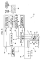
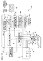
- a fluorescence endoscope device 100 includes a long, thin scope 2 to be inserted into a body cavity, an illuminating unit 20 including a light source 10 that emits illumination light from a tip 2a of the scope 2, an image-capturing unit 30 disposed in the scope 2 to obtain image information of an observation target site X, i.e., a subject, an image-processing section 40 that processes the image information obtained by the image-capturing unit 30, and a monitor 50 (display portion) on which the image and image information processed by the image-processing section 40 are displayed.
- an observation target site X i.e., a subject
- an image-processing section 40 that processes the image information obtained by the image-capturing unit 30
- a monitor 50 display portion
- the light source 10 includes a xenon lamp (Xe lamp) 11 that emits illumination light, an excitation light filter 13 that separates white light (reference light) containing excitation light from the illumination light emitted from the xenon lamp 11, and a coupling lens 15 that collects the white light containing the excitation light, separated by the excitation light filter 13.
- the excitation light filter 13 separates white light containing excitation light with a wavelength band of, for example, from 400 nm to 740 nm.
- the illuminating unit 20 includes a light-guide fiber 21 disposed substantially over the overall length of the scope 2 in the longitudinal direction, and a spreading lens 23 disposed at the tip 2a of the scope 2.
- the light-guide fiber 21 guides the white light containing the excitation light, collected by the coupling lens 15, to the tip 2a of the scope 2.
- the spreading lens 23 spreads the white light containing the excitation light, guided by the light-guide fiber 21, to illuminate the observation target site X.
- the image-capturing unit 30 includes an objective lens 31 that collects return light returning from the observation target site X irradiated with the white light containing the excitation light by the illuminating unit 20, and a beam splitter 33 that splits the return light, collected by the objective lens 31, according to the wavelength.
- the objective lens 31 is disposed beside the spreading lens 23 at the tip 2a of the scope 2.
- the beam splitter 33 reflects light (excitation light and fluorescence) having a longer wavelength than the excitation wavelength and allows white light (return light) that has a shorter wavelength than the excitation wavelength to pass therethrough.
- This image-capturing unit 30 includes an excitation-light cut filter 35 that, of the excitation light and fluorescence reflected by the beam splitter 33, blocks excitation light and allows only fluorescence (for example, near-infrared fluorescence) to pass therethrough, a focusing lens 37A that focuses fluorescence passing through the excitation-light cut filter 35, a focusing lens 37B that focuses white light passing through the beam splitter 33, a fluorescence-image-capturing portion 38 that captures an image of the fluorescence focused by the focusing lens 37A, and a white-light image-capturing portion 39 that captures an image of the white light focused by the focusing lens 37B.
- an excitation-light cut filter 35 that, of the excitation light and fluorescence reflected by the beam splitter 33, blocks excitation light and allows only fluorescence (for example, near-infrared fluorescence) to pass therethrough
- a focusing lens 37A that focuses fluorescence passing through the excitation-light cut filter 35
- the excitation-light cut filter 35 allows only fluorescence in the wavelength band from 765 nm to 850 nm to pass therethrough.
- the fluorescence-image-capturing portion 38 is, for example, a highly sensitive monochrome CCD for fluorescence. This fluorescence-image-capturing portion 38 obtains fluorescence image information by capturing an image of fluorescence.
- the white-light image-capturing portion 39 is, for example, a color CCD for white light and has a mosaic filter (not shown). This white-light image-capturing portion 39 obtains white-light image information by capturing an image of white light.
- the image-processing section 40 includes an image generating portion (a fluorescence-image acquisition portion and a reference-image acquisition portion) 41 that generates a fluorescence image and a white-light image (reference image), and a dividing portion (divided-fluorescence-image generating portion) 43 that divides the fluorescence image generated by the image generating portion 41 by the white-light image.
- the image generating portion 41 generates a two-dimensional fluorescence image from the fluorescence image information obtained by the fluorescence-image-capturing portion 38 and generates a two-dimensional white-light image from the white-light image information obtained by the white-light image-capturing portion 39.
- the dividing portion 43 divides the fluorescence image of the observation target site X by the white-light image of the same observation target site X to generate a divided fluorescence image, in which the variation in fluorescence intensity of the fluorescence image, which depends on the observation distance, the observation angle, etc., is reduced.
- the image-processing section 40 includes a first-threshold setting portion 45A that sets a first threshold of the gradation value of the fluorescence image, a second-threshold setting portion 45B that sets a second threshold of the gradation value of the divided fluorescence image generated by the dividing portion 43, a coordinate extracting portion 47 (a second-region extracting portion) that extracts predetermined coordinates of pixels of the divided fluorescence image, and a fluorescence-image correcting portion (a first-region extracting portion and a corrected-fluorescence-image generating portion) 49 that corrects the fluorescence image.
- a first-threshold setting portion 45A that sets a first threshold of the gradation value of the fluorescence image
- a second-threshold setting portion 45B that sets a second threshold of the gradation value of the divided fluorescence image generated by the dividing portion 43
- a coordinate extracting portion 47 (a second-region extracting portion) that extracts predetermined coordinates of pixels of
- the first-threshold setting portion 45A sets, as the first threshold, a threshold for removing a low-gradation region in the fluorescence image, such as a background, resulting from faint fluorescence emitted from a healthy site of the observation target site X. Furthermore, the first-threshold setting portion 45A outputs the set first threshold to the fluorescence-image correcting portion 49.
- the second-threshold setting portion 45B sets, as the second threshold, a threshold for removing a low-gradation region in the divided fluorescence image, such as a background of the observation target site X. Furthermore, the second-threshold setting portion 45B outputs the set second threshold to the coordinate extracting portion 47.
- the coordinate extracting portion 47 extracts the coordinates of the pixels of the divided fluorescence image having a gradation value lower than or equal to the second threshold inputted from the second-threshold setting portion 45B. Furthermore, the coordinate extracting portion 47 outputs the extracted coordinates to the fluorescence-image correcting portion 49.
- the fluorescence-image correcting portion 49 performs correction such that the gradation values of the pixels of the fluorescence image having a lower gradation value than the first threshold inputted from the first-threshold setting portion 45A are substituted with zero. Furthermore, the fluorescence-image correcting portion 49 performs correction such that the gradation values of the pixels of the corrected fluorescence image having the same coordinates as the coordinates extracted by the coordinate extracting portion 47 are substituted with zero. As a result, a corrected fluorescence image obtained by correcting the fluorescence image twice is generated. Furthermore, the fluorescence-image correcting portion 49 sends the generated corrected fluorescence image to the monitor 50, along with the white-light image and the fluorescence image.
- the monitor 50 can simultaneously display the white-light image and the fluorescence image or the corrected fluorescence image sent from the fluorescence-image correcting portion 49.
- a fluorescence agent that preferentially accumulates in a diseased site such as a cancer cell, is attached to or caused to be absorbed in the observation target site X.
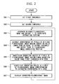
- the first-threshold setting portion 45A sets the first threshold (step SA1) and outputs the first threshold to the fluorescence-image correcting portion 49. Furthermore, the second-threshold setting portion 45B sets the second threshold (step SA2) and outputs the second threshold to the coordinate extracting portion 47.
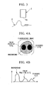
- the scope 2 is inserted into the body, and the tip 2a is made to face the observation target site X, as shown in FIG. 3 .
- white light containing excitation light which is emitted from the xenon lamp 11 and is separated by the excitation light filter 13, is collected by the coupling lens 15 and is guided to the tip 2a of the scope 2 by the light-guide fiber 21.
- This white light is spread by the spreading lens 23 and illuminates the observation target site X.
- the fluorescence agent attached thereto or caused to be absorbed therein is excited by the excitation light and emits fluorescence, and portions of the white light and the excitation light are reflected at the surface.
- the fluorescence, the white light, and the excitation light are collected by the objective lens 31, and the beam splitter 33 reflects light having a longer wavelength than the excitation wavelength, i.e., excitation light and fluorescence, and allows the white light that has a shorter wavelength than the excitation wavelength to pass therethrough.
- the excitation light and fluorescence reflected by the beam splitter 33 are incident on the excitation-light cut filter 35, where the excitation light is removed. Then, only the fluorescence is focused by the focusing lens 37A, and the fluorescence-image-capturing portion 38 captures the image thereof. Thus, the fluorescence-image-capturing portion 38 obtains the fluorescence image information of the observation target site X.
- the white light passing through the beam splitter 33 is focused by the focusing lens 37B, and the image thereof is captured by the white-light image-capturing portion 39.
- the white-light image-capturing portion 39 obtains the white-light image information of the observation target site X. Either of the fluorescence image information and the white-light image information may be obtained first; or they may be obtained simultaneously.
- the fluorescence image information obtained by the fluorescence-image-capturing portion 38 and the white-light image information obtained by the white-light image-capturing portion 39 are inputted to the image generating portion 41 of the image-processing section 40.
- the image generating portion 41 generates a two-dimensional fluorescence image, as shown in FIG. 4A , on the basis of the fluorescence image information and generates a two-dimensional white-light image on the basis of the white-light image information.
- the generated fluorescence image and white-light image are sent to the monitor 50 to be displayed via the fluorescence-image correcting portion 49.
- a fluorescence agent accumulates not only in a diseased site but also in a small amount in a healthy site, faint fluorescence is emitted also from areas other than the diseased site.
- the faint fluorescence emitted from areas other than the diseased site is displayed as a background image other than the diseased site etc., i.e., as a background, in the fluorescence image.
- a healthy site may be identified as a high-gradation region despite its faint fluorescence and may be displayed as a diseased site on the fluorescence image (hereinbelow, such a region is referred to as a "false positive site").
- the fluorescence image is mainly composed of a diseased-site region, a false-positive-site region, and a background region surrounding them.
- the horizontal axis indicates the gradation value
- the vertical axis indicates their frequencies in the entire corrected fluorescence image ( FIGS. 5B and 6B too).
- the fluorescence image and white-light image generated by the image generating portion 41 are sent to the dividing portion 43.
- the fluorescence image is divided by the white-light image to generate a divided fluorescence image, as shown in FIG. 5A .
- the generated divided fluorescence image is sent to the coordinate extracting portion 47 (step SA3).
- the false-positive-site region which exceeds the first threshold due to the influence of the observation distance and observation angle in the fluorescence image, does not exceed the second threshold and can be identified as a part of the background in the divided fluorescence image.
- the divided fluorescence image is mainly composed of a diseased-site region having a higher gradation value than the second threshold and a background region including a false positive site having a gradation value lower than or equal to the second threshold.
- the coordinate extracting portion 47 the coordinates of the pixels of the divided fluorescence image, sent from the dividing portion 43, having a gradation value lower than or equal to the second threshold inputted from the second-threshold setting portion 45B are extracted, and the extracted coordinates of the pixels are sent to the fluorescence-image correcting portion 49 (step SA4).
- the second region is distinguished from a low-gradation region, such as a background.
- the gradation values of the pixels of the fluorescence image having a lower gradation value than the first threshold inputted from the first-threshold setting portion 45A are substituted with zero (step SA5).
- the background of the fluorescence image is removed, and regions having a higher gradation value than the first threshold (first regions), i.e., a diseased-site region and a false-positive-site region, are extracted.
- the fluorescence-image correcting portion 49 substitutes the gradation values of the pixels of the fluorescence image, in which the diseased-site region and the false-positive-site region are extracted, corresponding to the coordinates inputted from the coordinate extracting portion 47 with zero (step SA6).
- the false-positive-site region in the fluorescence image is removed, and a corrected fluorescence image is generated, in which the diseased-site region, which is an overlap region of the first region in the fluorescence image and the second region in the divided fluorescence image, is extracted.
- the generated corrected fluorescence image is sent to the monitor 50 to be displayed (step SA7).
- steps SA3 to SA7 are repeated, and a new corrected fluorescence image is displayed on the monitor 50.
- the fluorescence endoscope device 100 by removing the background of the fluorescence image with the first-region extracting portion 45A and by removing the false positive site of the fluorescence image with the second-region extracting portion 45B and the corrected-fluorescence-image generating portion 49, it is possible to generate a corrected fluorescence image, in which only the diseased site is extracted by suppressing not only the influence of the background lower than the first threshold but also the influence of the false positive site higher than the first threshold.
- a corrected fluorescence image on the basis of the fluorescence image, it is possible to suppress the influence of the factors that degrade the image quality, which are specific to the white-light image and are reflected in the divided image, such as the information about the shapes of an edge portion, a shadow portion, etc., of the observation target site X, and the information about the colors of a breeding site, a blood vessel, etc., different from the color of the surrounding portion.
- the factors that degrade the image quality which are specific to the white-light image and are reflected in the divided image, such as the information about the shapes of an edge portion, a shadow portion, etc., of the observation target site X, and the information about the colors of a breeding site, a blood vessel, etc., different from the color of the surrounding portion.
- the coordinate extracting portion 47 extracts the coordinates of the pixels of the divided fluorescence image having a gradation value lower than or equal to the second threshold in this embodiment, the coordinate extracting portion 47 may instead directly extract the coordinate of the region (second region) of the divided fluorescence image having a higher gradation value than the second threshold.
- a corrected fluorescence image may be generated as a result of the coordinate extracting portion 47 outputting the coordinates of the second region to the fluorescence-image correcting portion 49 and as a result of the fluorescence-image correcting portion 49 substituting the gradation values of the pixels of the fluorescence image, in which the first region is extracted, other than the pixel corresponding to the coordinate of the second region (overlap region) with zero.
- the fluorescence-image correcting portion 49 substitutes the gradation values of the pixels of the fluorescence image having a lower gradation value than the first threshold with zero in the this embodiment, it is only necessary that the first region of the fluorescence image having a gradation value higher than the first threshold be extracted.
- the first region and the region having a lower gradation value than the first threshold may be displayed in different colors.
- the fluorescence-image correcting portion 49 substitutes the gradation values of the pixels of the fluorescence image having the same coordinates as the coordinates extracted by the coordinate extracting portion 47 with zero, it is only necessary that the overlap region of the first region of the fluorescence image and the second region of the divided fluorescence image having a gradation value higher than the second threshold be extracted from the fluorescence image.
- the overlap region and the region other than the overlap region may be displayed in different colors.
- This embodiment may be modified as follows.
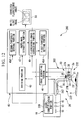
- a fluorescence endoscope device 101 may include a threshold input portion 61 for inputting the respective thresholds, and an operator may activate the threshold input portion 61 to manually input the first threshold and the second threshold to the first-threshold setting portion 45A and the second-threshold setting portion 45B. By doing so, the operator can set desired thresholds according to the observation object and the observation method.
- a phantom (standard sample) Y may be observed to set the first threshold and the second threshold.
- the phantom Y include a phantom having such a shape that a flat-plate-like base has two projections A and B, the projection A emitting fluorescence having a higher intensity than the surrounding area and showing a gradation value of 2000 on the fluorescence image, and the projection B emitting fluorescence having substantially the same intensity as the base and showing a gradation value of 1000 on the fluorescence image, when observed under predetermined observation conditions (distance and angle).
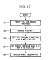
- the predetermined first threshold and second threshold are reset (step SB1), and the observation is started by disposing the phantom Y such that the observation distance between the scope 2 and the projections A and B is about 70% of the distance between the scope 2 and the base (step SB2).
- the image generating portion 41 generates a fluorescence image in which the base has a gradation value of 1000, the projection A has a gradation value of about 4000, and the projection B has a gradation value of about 2000.
- the base and the projection B each have a gradation value of 1000, and the projection A has a gradation value of about 4000.
- the first-threshold setting portion 45A sets the first threshold to, for example, 1500, so that only the projections A and B are displayed on the fluorescence image (step SB3). Furthermore, the second-threshold setting portion 45B sets the second threshold to 1500, so that the projection B, along with the base, is identified to be lower than or equal to the second threshold (step SB4).
- the respective thresholds it is possible to generate a corrected fluorescence image in which the base of the phantom Y, shown as the background, and the projection B, shown as the false positive site, are removed, and in which the projection A is shown. Accordingly, the observation target site X inside the body of a living body may be observed by using the first threshold and the second threshold (step SB5).
- thresholds for various observation objects can be set.
- a phantom having a tubular shape similar to the lumen of the large intestine may be used to set thresholds.
- a hollow phantom having a relatively large space may be used to set the thresholds.
- the fluorescence endoscope device 101 may include a storage portion 63 that stores the thresholds set by using a plurality of the phantoms Y, and a selecting portion 65 that selects the threshold corresponding to each phantom, stored in the storage portion 63.
- a precise threshold can be easily set when observation is performed under the same observation conditions, thereby simplifying the operation.
- a fluorescence endoscope device 200 may include a scope (endoscope scope) 202 that has an IC chip 267 storing scope information and that can be inserted and withdrawn, and the light source 10 may have a scope-identification portion 269 that determines the scope information stored in the IC chip 267.
- the scope information include the number of light-emitting portions 222, composed of a light-guide fiber 21 and a spreading lens 23, and the observation angle of a light-receiving portion 232, composed of the light-emitting portion 222 and the objective lens 31.
- the scope-identification portion 269 may read out the scope information stored in the IC chip 267 and output the scope information to the first-threshold setting portion (threshold setting portion) 45A and the second-threshold setting portion (threshold setting portion) 45B, and the first-threshold setting portion 45A and the second-threshold setting portion 45B may set the first threshold and the second threshold on the basis of the scope information.
- the phantom Y may be observed to set the first threshold and the second threshold.
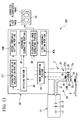
- a fluorescence endoscope device 300 may include a characteristic-value calculation portion 371 that calculates the average gradation value, m, of the pixels of the divided fluorescence image and the standard deviation, ⁇ , of that gradation value, and the second-threshold setting portion 45B may set a second threshold S on the basis of the sum of the average gradation value m and the standard deviation ⁇ , as shown in Formula 1 below.
- ⁇ Formula 1 ⁇ S a ⁇ m + b ⁇ ⁇ where a and b are coefficients.
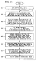
- the characteristic-value calculation portion 371 may calculate the average gradation value m of the entire divided fluorescence image and the standard deviation ⁇ thereof and output them to the second-threshold setting portion 45B (step SC3), and the second-threshold setting portion 45B may set the second threshold S using Formula 1 and output it to the coordinate extracting portion 47 (step SC4).
- Steps SC5 to SC8 are the same as steps SA4 to SA7 in FIG. 2 .
- coefficients a and b may be set such that they are inversely proportional to the estimated ratio of the diseased site in the divided fluorescence image. By doing so, it is possible to limit the minimum value and maximum value of the second threshold on the basis of the ratio of the region of pixels having a high-gradation value in the divided fluorescence image.
- the first-threshold setting portion 45A may also set the first threshold on the basis of the sum of the average gradation value of the entire fluorescence image and the standard deviation of that gradation value.
- the characteristic-value calculation portion 371 may calculate the average gradation value of the entire fluorescence image and the standard deviation thereof and output them to the first-threshold setting portion 45A.
- the fluorescence endoscope device 300 may include a coefficient input portion (not shown) for inputting coefficients a and b to the characteristic-value calculation portion 371.
- the second-threshold setting portion 45B sets the second threshold S on the basis of the sum of the average gradation value, m, of the pixels of the divided fluorescence image and the standard deviation, ⁇ , of that gradation value in this modification
- the second-threshold setting portion 45B may instead set the second threshold S on the basis of the sum of the modal gradation value or median gradation value of the pixels and the standard deviation, ⁇ , of that gradation value. For example, if the observation distance increases, the number of portions having a gradation value of 0 may increase in the corrected fluorescence image. In such a case, the average gradation value of the pixels is smaller than the gradation value resulting from the fluorescence from the background.
- the modal gradation value or median gradation value of the pixels instead of the average gradation value of the pixels, it is possible to reduce the influence of the pixels having a gradation value of 0, and to reflect the fluorescence intensity from the background more appropriately.
Landscapes
- Life Sciences & Earth Sciences (AREA)
- Health & Medical Sciences (AREA)
- Surgery (AREA)
- Engineering & Computer Science (AREA)
- Biophysics (AREA)
- Public Health (AREA)
- Veterinary Medicine (AREA)
- Physics & Mathematics (AREA)
- Pathology (AREA)
- General Health & Medical Sciences (AREA)
- Animal Behavior & Ethology (AREA)
- Biomedical Technology (AREA)
- Heart & Thoracic Surgery (AREA)
- Medical Informatics (AREA)
- Molecular Biology (AREA)
- Radiology & Medical Imaging (AREA)
- Optics & Photonics (AREA)
- Nuclear Medicine, Radiotherapy & Molecular Imaging (AREA)
- Signal Processing (AREA)
- Endoscopes (AREA)
- Investigating, Analyzing Materials By Fluorescence Or Luminescence (AREA)
Claims (9)
- Dispositif (100, 101, 200, 300) d'endoscope à fluorescence comprenant :une source de lumière (10) qui irradie un sujet avec une lumière d'excitation et une lumière d'éclairage ;une partie (41) d'acquisition d'image de fluorescence qui capture une image de la fluorescence générée au niveau du sujet en raison de l'irradiation avec la lumière d'excitation provenant de la source de lumière (10) pour obtenir une image de fluorescence ;une partie (41) d'acquisition d'image de référence qui capture une image de la lumière de retour revenant du sujet en raison de l'irradiation avec la lumière d'éclairage provenant de la source de lumière (10) pour obtenir une image de référence ; etune partie (43) de génération d'image de fluorescence divisée qui divise l'image de fluorescence par l'image de référence pour générer une image de fluorescence divisée ;caractérisé en ce que le dispositif (100, 101, 200, 300) d'endoscope à fluorescence comprend en outre :une partie (49) d'extraction de première région qui extrait une première région présentant une valeur de gradation supérieure à un premier seuil dans l'image de fluorescence ;une partie (47) d'extraction de deuxième région qui extrait une deuxième région présentant une valeur de gradation supérieure à un deuxième seuil dans l'image de fluorescence divisée ;une partie (49) de génération d'image de fluorescence corrigée qui génère une image de fluorescence corrigée dans laquelle une région de chevauchement, dans laquelle la première région de l'image de fluorescence extraite par la partie (49) d'extraction de première région chevauche la deuxième région de l'image de fluorescence divisée extraite par la partie (47) d'extraction de deuxième région, est extraite de l'image de fluorescence ; etune partie d'affichage (50) qui affiche l'image de fluorescence corrigée générée par la partie (49) de génération d'image de fluorescence corrigée.
- Dispositif (101) d'endoscope à fluorescence selon la revendication 1, comprenant en outre une partie (61) d'entrée de seuils destinée à délivrer en entrée le premier seuil et le deuxième seuil.
- Dispositif (100, 101, 200, 300) d'endoscope à fluorescence selon la revendication 1 ou 2, comprenant en outre une partie (45A) d'établissement de premier seuil qui établit le premier seuil sur la base d'une somme d'une valeur de gradation moyenne de chacun des pixels de l'image de fluorescence et d'une déviation standard de cette valeur de gradation.
- Dispositif (100, 101, 200, 300) d'endoscope à fluorescence selon l'une quelconque des revendications 1 à 3, comprenant en outre une partie (45B) d'établissement de deuxième seuil qui établit le deuxième seuil sur la base d'une somme d'une valeur de gradation moyenne de chacun des pixels de l'image de fluorescence divisée et d'une déviation standard de cette valeur de gradation.
- Dispositif (100, 101, 200, 300) d'endoscope à fluorescence selon la revendication 1 ou 2, comprenant en outre une partie (45A) d'établissement de premier seuil qui établit le premier seuil sur la base d'une somme d'une valeur de gradation modale de chacun des pixels de l'image de fluorescence et d'une déviation standard de cette valeur de gradation.
- Dispositif (100, 101, 200, 300) d'endoscope à fluorescence selon l'une quelconque des revendications 1, 2 et 5, comprenant en outre une partie (45B) d'établissement de deuxième seuil qui établit le deuxième seuil sur la base d'une somme d'une valeur de gradation modale de chacun des pixels de l'image de fluorescence divisée et d'une déviation standard de cette valeur de gradation.
- Dispositif (100, 101, 200, 300) d'endoscope à fluorescence selon la revendication 1 ou 2, comprenant en outre une partie (45A) d'établissement de premier seuil qui établit le premier seuil sur la base d'une somme d'une valeur de gradation médiane de chacun des pixels de l'image de fluorescence et d'une déviation standard de cette valeur de gradation.
- Dispositif (100, 101, 200, 300) d'endoscope à fluorescence selon l'une quelconque des revendications 1, 2 et 7, comprenant en outre une partie (45B) d'établissement de deuxième seuil qui établit le deuxième seuil sur la base d'une somme d'une valeur de gradation médiane de chacun des pixels de l'image de fluorescence divisée et d'une déviation standard de cette valeur de gradation.
- Dispositif (200) d'endoscope à fluorescence selon l'une quelconque des revendications 1 à 8, comprenant en outre :un scope (202) d'endoscope comprenant, au niveau d'une pointe (2a) de celui-ci, une partie (222) d'émission de lumière qui émet la lumière d'excitation et la lumière de référence et une partie (232) de réception de lumière qui reçoit la lumière fluorescente et la lumière de retour ; etune partie (269) d'établissement de seuil qui établit le premier seuil et le deuxième seuil sur la base des informations de scope concernant la partie (222) d'émission de lumière et la partie (232) de réception de lumière du scope (202) d'endoscope.
Applications Claiming Priority (2)
| Application Number | Priority Date | Filing Date | Title |
|---|---|---|---|
| JP2010027886 | 2010-02-10 | ||
| PCT/JP2011/051445 WO2011099363A1 (fr) | 2010-02-10 | 2011-01-26 | Dispositif d'endoscope à fluorescence |
Publications (3)
| Publication Number | Publication Date |
|---|---|
| EP2520211A1 EP2520211A1 (fr) | 2012-11-07 |
| EP2520211A4 EP2520211A4 (fr) | 2012-12-12 |
| EP2520211B1 true EP2520211B1 (fr) | 2014-04-23 |
Family
ID=44367645
Family Applications (1)
| Application Number | Title | Priority Date | Filing Date |
|---|---|---|---|
| EP11742110.7A Not-in-force EP2520211B1 (fr) | 2010-02-10 | 2011-01-26 | Dispositif d'endoscope a fluorescence |
Country Status (5)
| Country | Link |
|---|---|
| US (1) | US9498109B2 (fr) |
| EP (1) | EP2520211B1 (fr) |
| JP (1) | JP5444377B2 (fr) |
| CN (1) | CN102753079B (fr) |
| WO (1) | WO2011099363A1 (fr) |
Families Citing this family (19)
| Publication number | Priority date | Publication date | Assignee | Title |
|---|---|---|---|---|
| JP5592715B2 (ja) * | 2010-07-02 | 2014-09-17 | オリンパス株式会社 | 画像処理装置および画像処理方法 |
| JP5816486B2 (ja) | 2011-08-18 | 2015-11-18 | オリンパス株式会社 | 蛍光観察装置および蛍光観察システム並びに蛍光観察装置の蛍光画像処理方法 |
| JP5926909B2 (ja) * | 2011-09-07 | 2016-05-25 | オリンパス株式会社 | 蛍光観察装置 |
| JP6005918B2 (ja) * | 2011-09-08 | 2016-10-12 | オリンパス株式会社 | 蛍光観察装置 |
| WO2013100030A1 (fr) * | 2011-12-28 | 2013-07-04 | オリンパス株式会社 | Dispositif d'observation de lumière fluorescente, procédé d'observation de lumière fluorescente et procédé de fonctionnement du dispositif d'observation de lumière fluorescente |
| JP6089436B2 (ja) * | 2012-04-18 | 2017-03-08 | ソニー株式会社 | 画像処理装置と画像処理装置の作動方法および撮像装置 |
| JP6017219B2 (ja) * | 2012-08-01 | 2016-10-26 | オリンパス株式会社 | 蛍光観察装置および蛍光観察システム |
| KR20140102521A (ko) | 2013-02-14 | 2014-08-22 | 삼성전자주식회사 | 내시경 장치 및 그 제어 방법 |
| CN108814525A (zh) * | 2018-03-20 | 2018-11-16 | 广东欧谱曼迪科技有限公司 | 调焦反馈的荧光导航内窥镜系统及激光功率自动调整方法 |
| CN108523819B (zh) * | 2018-03-20 | 2024-03-22 | 广东欧谱曼迪科技有限公司 | 测光反馈的荧光导航内窥镜系统及激光功率自动调整方法 |
| JP2021097648A (ja) * | 2019-12-23 | 2021-07-01 | 横河電機株式会社 | 核酸配列計測装置及び核酸配列計測方法 |
| JP7667852B2 (ja) * | 2020-08-06 | 2025-04-23 | キヤノン ユーエスエイ,インコーポレイテッド | カテーテルベースのマルチモーダル画像における潜在的な偽陽性及び盲点の位置を特定するためのシステム及び方法 |
| EP4322821A4 (fr) * | 2021-04-14 | 2025-02-05 | Arthrex, Inc. | Système et procédé d'utilisation d'un rayonnement détectable en chirurgie |
| US20230076477A1 (en) * | 2021-09-05 | 2023-03-09 | Shimadzu Corporation | Imaging device and imaging method |
| CN114298980A (zh) * | 2021-12-09 | 2022-04-08 | 杭州海康慧影科技有限公司 | 一种图像处理方法、装置及设备 |
| US12239409B2 (en) | 2022-02-28 | 2025-03-04 | Visionsense Ltd. | Fluorescence imaging camera assembly for open surgery |
| CN114903408A (zh) * | 2022-04-22 | 2022-08-16 | 华伦医疗用品(深圳)有限公司 | 一种具有诊断成像的内窥镜成像系统 |
| CN115150390B (zh) * | 2022-06-27 | 2024-04-09 | 山东信通电子股份有限公司 | 一种图像显示方法、装置、设备及介质 |
| CN117437247B (zh) * | 2023-12-18 | 2024-03-05 | 津泰(天津)医疗器械有限公司 | 一种基于自然腔道影像的病变区域提取分割方法 |
Family Cites Families (14)
| Publication number | Priority date | Publication date | Assignee | Title |
|---|---|---|---|---|
| JPS62247232A (ja) | 1986-04-21 | 1987-10-28 | Agency Of Ind Science & Technol | 蛍光測定装置 |
| JPH0358279A (ja) | 1989-07-27 | 1991-03-13 | Nec Corp | 論理シミュレータ |
| DE69938493T2 (de) * | 1998-01-26 | 2009-05-20 | Massachusetts Institute Of Technology, Cambridge | Endoskop zur erfassung von fluoreszenzbilder |
| JP4202671B2 (ja) | 2001-04-27 | 2008-12-24 | 富士フイルム株式会社 | 規格化画像生成方法および装置 |
| JP3862582B2 (ja) * | 2001-06-29 | 2006-12-27 | 富士フイルムホールディングス株式会社 | 蛍光画像取得方法および装置並びにプログラム |
| JP4109132B2 (ja) * | 2002-03-28 | 2008-07-02 | 富士フイルム株式会社 | 蛍光判定装置 |
| JP3802508B2 (ja) * | 2003-04-21 | 2006-07-26 | アロカ株式会社 | 超音波診断装置 |
| JP2006175052A (ja) * | 2004-12-22 | 2006-07-06 | Fuji Photo Film Co Ltd | 蛍光画像撮像装置 |
| JP2007215927A (ja) * | 2006-02-20 | 2007-08-30 | Pentax Corp | 内視鏡プロセッサ、擬似カラー画像生成プログラム、及び蛍光内視鏡システム |
| JP5019866B2 (ja) | 2006-12-25 | 2012-09-05 | オリンパス株式会社 | 蛍光内視鏡及び蛍光内視鏡の作動方法 |
| JP5074044B2 (ja) * | 2007-01-18 | 2012-11-14 | オリンパス株式会社 | 蛍光観察装置および蛍光観察装置の作動方法 |
| JP5396004B2 (ja) * | 2007-01-31 | 2014-01-22 | オリンパス株式会社 | 蛍光観察装置および蛍光観察装置の作動方法 |
| JP5081720B2 (ja) * | 2008-05-22 | 2012-11-28 | 富士フイルム株式会社 | 蛍光内視鏡装置および励起光ユニット |
| US20100080459A1 (en) * | 2008-09-26 | 2010-04-01 | Qualcomm Incorporated | Content adaptive histogram enhancement |
-
2011
- 2011-01-26 JP JP2011553792A patent/JP5444377B2/ja not_active Expired - Fee Related
- 2011-01-26 EP EP11742110.7A patent/EP2520211B1/fr not_active Not-in-force
- 2011-01-26 WO PCT/JP2011/051445 patent/WO2011099363A1/fr not_active Ceased
- 2011-01-26 CN CN201180008583.7A patent/CN102753079B/zh not_active Expired - Fee Related
-
2012
- 2012-08-02 US US13/565,440 patent/US9498109B2/en active Active
Also Published As
| Publication number | Publication date |
|---|---|
| CN102753079B (zh) | 2015-06-03 |
| EP2520211A4 (fr) | 2012-12-12 |
| CN102753079A (zh) | 2012-10-24 |
| EP2520211A1 (fr) | 2012-11-07 |
| US9498109B2 (en) | 2016-11-22 |
| JPWO2011099363A1 (ja) | 2013-06-13 |
| US20120302893A1 (en) | 2012-11-29 |
| WO2011099363A1 (fr) | 2011-08-18 |
| JP5444377B2 (ja) | 2014-03-19 |
Similar Documents
| Publication | Publication Date | Title |
|---|---|---|
| EP2520211B1 (fr) | Dispositif d'endoscope a fluorescence | |
| US9532719B2 (en) | Fluorescence endoscope apparatus | |
| JP5816486B2 (ja) | 蛍光観察装置および蛍光観察システム並びに蛍光観察装置の蛍光画像処理方法 | |
| US9417188B2 (en) | Fluorescence observation device | |
| EP2520212B1 (fr) | Dispositif d'endoscope à fluorescence | |
| US9119553B2 (en) | Fluorescence endoscope device | |
| CN104010558B (zh) | 荧光观察装置、荧光观察方法以及荧光观察装置的工作方法 | |
| US9518924B2 (en) | Fluoroscopy apparatus and fluoroscopy apparatus operating method | |
| US9052286B2 (en) | Fluorescence endoscope apparatus | |
| EP2620092B1 (fr) | Dispositif d'observation de fluorescence | |
| JP2015029841A (ja) | 撮像装置および撮像方法 | |
| CN106659360A (zh) | 诊断支援装置和诊断支援信息显示方法 | |
| EP2589328A1 (fr) | Appareil de traitement d'image et procédé de traitement d'image |
Legal Events
| Date | Code | Title | Description |
|---|---|---|---|
| PUAI | Public reference made under article 153(3) epc to a published international application that has entered the european phase |
Free format text: ORIGINAL CODE: 0009012 |
|
| 17P | Request for examination filed |
Effective date: 20120803 |
|
| AK | Designated contracting states |
Kind code of ref document: A1 Designated state(s): AL AT BE BG CH CY CZ DE DK EE ES FI FR GB GR HR HU IE IS IT LI LT LU LV MC MK MT NL NO PL PT RO RS SE SI SK SM TR |
|
| A4 | Supplementary search report drawn up and despatched |
Effective date: 20121109 |
|
| RIC1 | Information provided on ipc code assigned before grant |
Ipc: A61B 1/05 20060101ALI20121105BHEP Ipc: G01N 21/64 20060101ALI20121105BHEP Ipc: A61B 1/04 20060101ALI20121105BHEP Ipc: A61B 1/00 20060101AFI20121105BHEP Ipc: A61B 5/00 20060101ALI20121105BHEP Ipc: A61B 1/06 20060101ALI20121105BHEP Ipc: A61B 1/07 20060101ALI20121105BHEP |
|
| DAX | Request for extension of the european patent (deleted) | ||
| GRAP | Despatch of communication of intention to grant a patent |
Free format text: ORIGINAL CODE: EPIDOSNIGR1 |
|
| INTG | Intention to grant announced |
Effective date: 20131114 |
|
| GRAS | Grant fee paid |
Free format text: ORIGINAL CODE: EPIDOSNIGR3 |
|
| GRAA | (expected) grant |
Free format text: ORIGINAL CODE: 0009210 |
|
| AK | Designated contracting states |
Kind code of ref document: B1 Designated state(s): AL AT BE BG CH CY CZ DE DK EE ES FI FR GB GR HR HU IE IS IT LI LT LU LV MC MK MT NL NO PL PT RO RS SE SI SK SM TR |
|
| REG | Reference to a national code |
Ref country code: GB Ref legal event code: FG4D |
|
| REG | Reference to a national code |
Ref country code: CH Ref legal event code: EP |
|
| REG | Reference to a national code |
Ref country code: AT Ref legal event code: REF Ref document number: 663267 Country of ref document: AT Kind code of ref document: T Effective date: 20140515 |
|
| REG | Reference to a national code |
Ref country code: IE Ref legal event code: FG4D |
|
| REG | Reference to a national code |
Ref country code: DE Ref legal event code: R096 Ref document number: 602011006423 Country of ref document: DE Effective date: 20140612 |
|
| REG | Reference to a national code |
Ref country code: AT Ref legal event code: MK05 Ref document number: 663267 Country of ref document: AT Kind code of ref document: T Effective date: 20140423 |
|
| REG | Reference to a national code |
Ref country code: NL Ref legal event code: VDEP Effective date: 20140423 |
|
| REG | Reference to a national code |
Ref country code: LT Ref legal event code: MG4D |
|
| PG25 | Lapsed in a contracting state [announced via postgrant information from national office to epo] |
Ref country code: LT Free format text: LAPSE BECAUSE OF FAILURE TO SUBMIT A TRANSLATION OF THE DESCRIPTION OR TO PAY THE FEE WITHIN THE PRESCRIBED TIME-LIMIT Effective date: 20140423 Ref country code: CY Free format text: LAPSE BECAUSE OF FAILURE TO SUBMIT A TRANSLATION OF THE DESCRIPTION OR TO PAY THE FEE WITHIN THE PRESCRIBED TIME-LIMIT Effective date: 20140423 Ref country code: FI Free format text: LAPSE BECAUSE OF FAILURE TO SUBMIT A TRANSLATION OF THE DESCRIPTION OR TO PAY THE FEE WITHIN THE PRESCRIBED TIME-LIMIT Effective date: 20140423 Ref country code: IS Free format text: LAPSE BECAUSE OF FAILURE TO SUBMIT A TRANSLATION OF THE DESCRIPTION OR TO PAY THE FEE WITHIN THE PRESCRIBED TIME-LIMIT Effective date: 20140823 Ref country code: NL Free format text: LAPSE BECAUSE OF FAILURE TO SUBMIT A TRANSLATION OF THE DESCRIPTION OR TO PAY THE FEE WITHIN THE PRESCRIBED TIME-LIMIT Effective date: 20140423 Ref country code: NO Free format text: LAPSE BECAUSE OF FAILURE TO SUBMIT A TRANSLATION OF THE DESCRIPTION OR TO PAY THE FEE WITHIN THE PRESCRIBED TIME-LIMIT Effective date: 20140723 Ref country code: GR Free format text: LAPSE BECAUSE OF FAILURE TO SUBMIT A TRANSLATION OF THE DESCRIPTION OR TO PAY THE FEE WITHIN THE PRESCRIBED TIME-LIMIT Effective date: 20140724 Ref country code: BG Free format text: LAPSE BECAUSE OF FAILURE TO SUBMIT A TRANSLATION OF THE DESCRIPTION OR TO PAY THE FEE WITHIN THE PRESCRIBED TIME-LIMIT Effective date: 20140723 |
|
| PG25 | Lapsed in a contracting state [announced via postgrant information from national office to epo] |
Ref country code: PL Free format text: LAPSE BECAUSE OF FAILURE TO SUBMIT A TRANSLATION OF THE DESCRIPTION OR TO PAY THE FEE WITHIN THE PRESCRIBED TIME-LIMIT Effective date: 20140423 Ref country code: HR Free format text: LAPSE BECAUSE OF FAILURE TO SUBMIT A TRANSLATION OF THE DESCRIPTION OR TO PAY THE FEE WITHIN THE PRESCRIBED TIME-LIMIT Effective date: 20140423 Ref country code: SE Free format text: LAPSE BECAUSE OF FAILURE TO SUBMIT A TRANSLATION OF THE DESCRIPTION OR TO PAY THE FEE WITHIN THE PRESCRIBED TIME-LIMIT Effective date: 20140423 Ref country code: AT Free format text: LAPSE BECAUSE OF FAILURE TO SUBMIT A TRANSLATION OF THE DESCRIPTION OR TO PAY THE FEE WITHIN THE PRESCRIBED TIME-LIMIT Effective date: 20140423 Ref country code: ES Free format text: LAPSE BECAUSE OF FAILURE TO SUBMIT A TRANSLATION OF THE DESCRIPTION OR TO PAY THE FEE WITHIN THE PRESCRIBED TIME-LIMIT Effective date: 20140423 Ref country code: RS Free format text: LAPSE BECAUSE OF FAILURE TO SUBMIT A TRANSLATION OF THE DESCRIPTION OR TO PAY THE FEE WITHIN THE PRESCRIBED TIME-LIMIT Effective date: 20140423 Ref country code: LV Free format text: LAPSE BECAUSE OF FAILURE TO SUBMIT A TRANSLATION OF THE DESCRIPTION OR TO PAY THE FEE WITHIN THE PRESCRIBED TIME-LIMIT Effective date: 20140423 |
|
| PG25 | Lapsed in a contracting state [announced via postgrant information from national office to epo] |
Ref country code: PT Free format text: LAPSE BECAUSE OF FAILURE TO SUBMIT A TRANSLATION OF THE DESCRIPTION OR TO PAY THE FEE WITHIN THE PRESCRIBED TIME-LIMIT Effective date: 20140825 |
|
| REG | Reference to a national code |
Ref country code: DE Ref legal event code: R097 Ref document number: 602011006423 Country of ref document: DE |
|
| PG25 | Lapsed in a contracting state [announced via postgrant information from national office to epo] |
Ref country code: CZ Free format text: LAPSE BECAUSE OF FAILURE TO SUBMIT A TRANSLATION OF THE DESCRIPTION OR TO PAY THE FEE WITHIN THE PRESCRIBED TIME-LIMIT Effective date: 20140423 Ref country code: SK Free format text: LAPSE BECAUSE OF FAILURE TO SUBMIT A TRANSLATION OF THE DESCRIPTION OR TO PAY THE FEE WITHIN THE PRESCRIBED TIME-LIMIT Effective date: 20140423 Ref country code: DK Free format text: LAPSE BECAUSE OF FAILURE TO SUBMIT A TRANSLATION OF THE DESCRIPTION OR TO PAY THE FEE WITHIN THE PRESCRIBED TIME-LIMIT Effective date: 20140423 Ref country code: BE Free format text: LAPSE BECAUSE OF FAILURE TO SUBMIT A TRANSLATION OF THE DESCRIPTION OR TO PAY THE FEE WITHIN THE PRESCRIBED TIME-LIMIT Effective date: 20140423 Ref country code: RO Free format text: LAPSE BECAUSE OF FAILURE TO SUBMIT A TRANSLATION OF THE DESCRIPTION OR TO PAY THE FEE WITHIN THE PRESCRIBED TIME-LIMIT Effective date: 20140423 Ref country code: EE Free format text: LAPSE BECAUSE OF FAILURE TO SUBMIT A TRANSLATION OF THE DESCRIPTION OR TO PAY THE FEE WITHIN THE PRESCRIBED TIME-LIMIT Effective date: 20140423 |
|
| PLBE | No opposition filed within time limit |
Free format text: ORIGINAL CODE: 0009261 |
|
| STAA | Information on the status of an ep patent application or granted ep patent |
Free format text: STATUS: NO OPPOSITION FILED WITHIN TIME LIMIT |
|
| PG25 | Lapsed in a contracting state [announced via postgrant information from national office to epo] |
Ref country code: IT Free format text: LAPSE BECAUSE OF FAILURE TO SUBMIT A TRANSLATION OF THE DESCRIPTION OR TO PAY THE FEE WITHIN THE PRESCRIBED TIME-LIMIT Effective date: 20140423 |
|
| 26N | No opposition filed |
Effective date: 20150126 |
|
| REG | Reference to a national code |
Ref country code: DE Ref legal event code: R097 Ref document number: 602011006423 Country of ref document: DE Effective date: 20150126 |
|
| PG25 | Lapsed in a contracting state [announced via postgrant information from national office to epo] |
Ref country code: SI Free format text: LAPSE BECAUSE OF FAILURE TO SUBMIT A TRANSLATION OF THE DESCRIPTION OR TO PAY THE FEE WITHIN THE PRESCRIBED TIME-LIMIT Effective date: 20140423 |
|
| REG | Reference to a national code |
Ref country code: CH Ref legal event code: PL |
|
| PG25 | Lapsed in a contracting state [announced via postgrant information from national office to epo] |
Ref country code: LU Free format text: LAPSE BECAUSE OF FAILURE TO SUBMIT A TRANSLATION OF THE DESCRIPTION OR TO PAY THE FEE WITHIN THE PRESCRIBED TIME-LIMIT Effective date: 20150126 |
|
| PG25 | Lapsed in a contracting state [announced via postgrant information from national office to epo] |
Ref country code: MC Free format text: LAPSE BECAUSE OF FAILURE TO SUBMIT A TRANSLATION OF THE DESCRIPTION OR TO PAY THE FEE WITHIN THE PRESCRIBED TIME-LIMIT Effective date: 20140423 |
|
| PG25 | Lapsed in a contracting state [announced via postgrant information from national office to epo] |
Ref country code: CH Free format text: LAPSE BECAUSE OF NON-PAYMENT OF DUE FEES Effective date: 20150131 Ref country code: LI Free format text: LAPSE BECAUSE OF NON-PAYMENT OF DUE FEES Effective date: 20150131 |
|
| REG | Reference to a national code |
Ref country code: IE Ref legal event code: MM4A |
|
| REG | Reference to a national code |
Ref country code: FR Ref legal event code: PLFP Year of fee payment: 6 |
|
| PG25 | Lapsed in a contracting state [announced via postgrant information from national office to epo] |
Ref country code: IE Free format text: LAPSE BECAUSE OF NON-PAYMENT OF DUE FEES Effective date: 20150126 |
|
| PGFP | Annual fee paid to national office [announced via postgrant information from national office to epo] |
Ref country code: FR Payment date: 20151208 Year of fee payment: 6 |
|
| PGFP | Annual fee paid to national office [announced via postgrant information from national office to epo] |
Ref country code: GB Payment date: 20160120 Year of fee payment: 6 |
|
| REG | Reference to a national code |
Ref country code: FR Ref legal event code: CA Effective date: 20161108 |
|
| PG25 | Lapsed in a contracting state [announced via postgrant information from national office to epo] |
Ref country code: MT Free format text: LAPSE BECAUSE OF FAILURE TO SUBMIT A TRANSLATION OF THE DESCRIPTION OR TO PAY THE FEE WITHIN THE PRESCRIBED TIME-LIMIT Effective date: 20140423 |
|
| PG25 | Lapsed in a contracting state [announced via postgrant information from national office to epo] |
Ref country code: SM Free format text: LAPSE BECAUSE OF FAILURE TO SUBMIT A TRANSLATION OF THE DESCRIPTION OR TO PAY THE FEE WITHIN THE PRESCRIBED TIME-LIMIT Effective date: 20140423 Ref country code: HU Free format text: LAPSE BECAUSE OF FAILURE TO SUBMIT A TRANSLATION OF THE DESCRIPTION OR TO PAY THE FEE WITHIN THE PRESCRIBED TIME-LIMIT; INVALID AB INITIO Effective date: 20110126 |
|
| PG25 | Lapsed in a contracting state [announced via postgrant information from national office to epo] |
Ref country code: TR Free format text: LAPSE BECAUSE OF FAILURE TO SUBMIT A TRANSLATION OF THE DESCRIPTION OR TO PAY THE FEE WITHIN THE PRESCRIBED TIME-LIMIT Effective date: 20140423 |
|
| GBPC | Gb: european patent ceased through non-payment of renewal fee |
Effective date: 20170126 |
|
| REG | Reference to a national code |
Ref country code: FR Ref legal event code: ST Effective date: 20170929 |
|
| PG25 | Lapsed in a contracting state [announced via postgrant information from national office to epo] |
Ref country code: FR Free format text: LAPSE BECAUSE OF NON-PAYMENT OF DUE FEES Effective date: 20170131 |
|
| PG25 | Lapsed in a contracting state [announced via postgrant information from national office to epo] |
Ref country code: GB Free format text: LAPSE BECAUSE OF NON-PAYMENT OF DUE FEES Effective date: 20170126 |
|
| PGFP | Annual fee paid to national office [announced via postgrant information from national office to epo] |
Ref country code: DE Payment date: 20180117 Year of fee payment: 8 |
|
| PG25 | Lapsed in a contracting state [announced via postgrant information from national office to epo] |
Ref country code: MK Free format text: LAPSE BECAUSE OF FAILURE TO SUBMIT A TRANSLATION OF THE DESCRIPTION OR TO PAY THE FEE WITHIN THE PRESCRIBED TIME-LIMIT Effective date: 20140423 |
|
| PG25 | Lapsed in a contracting state [announced via postgrant information from national office to epo] |
Ref country code: AL Free format text: LAPSE BECAUSE OF FAILURE TO SUBMIT A TRANSLATION OF THE DESCRIPTION OR TO PAY THE FEE WITHIN THE PRESCRIBED TIME-LIMIT Effective date: 20140423 |
|
| REG | Reference to a national code |
Ref country code: DE Ref legal event code: R119 Ref document number: 602011006423 Country of ref document: DE |
|
| PG25 | Lapsed in a contracting state [announced via postgrant information from national office to epo] |
Ref country code: DE Free format text: LAPSE BECAUSE OF NON-PAYMENT OF DUE FEES Effective date: 20190801 |