EP2520448A1 - Ensemble de véhicule et suspension de roue - Google Patents
Ensemble de véhicule et suspension de roue Download PDFInfo
- Publication number
- EP2520448A1 EP2520448A1 EP12163535A EP12163535A EP2520448A1 EP 2520448 A1 EP2520448 A1 EP 2520448A1 EP 12163535 A EP12163535 A EP 12163535A EP 12163535 A EP12163535 A EP 12163535A EP 2520448 A1 EP2520448 A1 EP 2520448A1
- Authority
- EP
- European Patent Office
- Prior art keywords
- vehicle
- carrier body
- wheel
- pair
- pivot arm
- Prior art date
- Legal status (The legal status is an assumption and is not a legal conclusion. Google has not performed a legal analysis and makes no representation as to the accuracy of the status listed.)
- Granted
Links
- 239000000725 suspension Substances 0.000 title claims description 25
- 238000010276 construction Methods 0.000 claims abstract description 26
- 229910000831 Steel Inorganic materials 0.000 claims description 9
- 239000010959 steel Substances 0.000 claims description 9
- 239000000463 material Substances 0.000 claims description 6
- 229910001220 stainless steel Inorganic materials 0.000 claims description 5
- 239000010935 stainless steel Substances 0.000 claims description 5
- 229910001335 Galvanized steel Inorganic materials 0.000 claims description 2
- 239000008397 galvanized steel Substances 0.000 claims description 2
- 239000002650 laminated plastic Substances 0.000 claims description 2
- 238000006243 chemical reaction Methods 0.000 description 10
- 239000004033 plastic Substances 0.000 description 3
- 239000006096 absorbing agent Substances 0.000 description 2
- 239000004411 aluminium Substances 0.000 description 2
- 229910052782 aluminium Inorganic materials 0.000 description 2
- XAGFODPZIPBFFR-UHFFFAOYSA-N aluminium Chemical compound [Al] XAGFODPZIPBFFR-UHFFFAOYSA-N 0.000 description 2
- 230000004048 modification Effects 0.000 description 2
- 238000012986 modification Methods 0.000 description 2
- 230000035939 shock Effects 0.000 description 2
- 239000002131 composite material Substances 0.000 description 1
- 230000009977 dual effect Effects 0.000 description 1
- 239000002828 fuel tank Substances 0.000 description 1
- 239000011521 glass Substances 0.000 description 1
- 229910052751 metal Inorganic materials 0.000 description 1
- 239000002184 metal Substances 0.000 description 1
- 238000003466 welding Methods 0.000 description 1
Images

Classifications
-
- B—PERFORMING OPERATIONS; TRANSPORTING
- B60—VEHICLES IN GENERAL
- B60G—VEHICLE SUSPENSION ARRANGEMENTS
- B60G7/00—Pivoted suspension arms; Accessories thereof
- B60G7/02—Attaching arms to sprung part of vehicle
-
- B—PERFORMING OPERATIONS; TRANSPORTING
- B60—VEHICLES IN GENERAL
- B60G—VEHICLE SUSPENSION ARRANGEMENTS
- B60G3/00—Resilient suspensions for a single wheel
- B60G3/18—Resilient suspensions for a single wheel with two or more pivoted arms, e.g. parallelogram
- B60G3/20—Resilient suspensions for a single wheel with two or more pivoted arms, e.g. parallelogram all arms being rigid
-
- B—PERFORMING OPERATIONS; TRANSPORTING
- B60—VEHICLES IN GENERAL
- B60G—VEHICLE SUSPENSION ARRANGEMENTS
- B60G2200/00—Indexing codes relating to suspension types
- B60G2200/10—Independent suspensions
- B60G2200/14—Independent suspensions with lateral arms
-
- B—PERFORMING OPERATIONS; TRANSPORTING
- B60—VEHICLES IN GENERAL
- B60G—VEHICLE SUSPENSION ARRANGEMENTS
- B60G2204/00—Indexing codes related to suspensions per se or to auxiliary parts
- B60G2204/10—Mounting of suspension elements
- B60G2204/14—Mounting of suspension arms
- B60G2204/143—Mounting of suspension arms on the vehicle body or chassis
-
- B—PERFORMING OPERATIONS; TRANSPORTING
- B60—VEHICLES IN GENERAL
- B60G—VEHICLE SUSPENSION ARRANGEMENTS
- B60G2204/00—Indexing codes related to suspensions per se or to auxiliary parts
- B60G2204/10—Mounting of suspension elements
- B60G2204/15—Mounting of subframes
-
- B—PERFORMING OPERATIONS; TRANSPORTING
- B60—VEHICLES IN GENERAL
- B60G—VEHICLE SUSPENSION ARRANGEMENTS
- B60G2206/00—Indexing codes related to the manufacturing of suspensions: constructional features, the materials used, procedures or tools
- B60G2206/01—Constructional features of suspension elements, e.g. arms, dampers, springs
- B60G2206/60—Subframe construction
-
- B—PERFORMING OPERATIONS; TRANSPORTING
- B60—VEHICLES IN GENERAL
- B60G—VEHICLE SUSPENSION ARRANGEMENTS
- B60G2300/00—Indexing codes relating to the type of vehicle
- B60G2300/34—Ambulances
-
- B—PERFORMING OPERATIONS; TRANSPORTING
- B60—VEHICLES IN GENERAL
- B60G—VEHICLE SUSPENSION ARRANGEMENTS
- B60G2300/00—Indexing codes relating to the type of vehicle
- B60G2300/38—Low or lowerable bed vehicles
Definitions
- the present invention relates to a vehicle comprising a bodywork with a mobile chassis, which bodywork comprises a bottom with a loading floor which supports on at least a first wheel and an opposite second wheel, wherein the first wheel and the second wheel are suspended for movement independently of each other within respectively a first spring path and a second spring path under the influence of spring means provided for this purpose.
- the invention relates to a wheel suspension assembly for a vehicle.
- This relates particularly to a vehicle which is supplied for instance as standard delivery van or passenger car with a loading space in the rear of the vehicle and which is adapted for the purpose of wheelchair transport for the disabled. It is important here that the person sitting in a wheelchair retains sufficient head room and can preferably be seated in the vehicle on a flat, non-inclining loading floor. With a view hereto an existing standard loading floor of the vehicle, with which the vehicle is fitted in the factory, must usually be lowered. This usually means that the original loading floor will be replaced by one that is lower.
- Such a rigid rear axle in vans is however increasingly also being replaced by an independent rear wheel suspension, this with a view to travel comfort, as has long been the case for the same reason in passenger cars.
- An independent rear wheel suspension provides for a free spring path of both wheels independently of each other in order to thus be able to better compensate for local unevenness in a road surface. From a structural viewpoint this requires the placing of reaction arms which extend, for instance centrally between the rear wheels, pivotally from the bottom under the loading floor and which are connected at a free outer end to the wheels. This central placing of the reaction arms forms in practice an obstacle to lowering of the bottom with loading floor.
- the present invention has for its object, among others, to provide a vehicle with an independent rear wheel suspension and a relatively low loading floor, in particular a loading floor below a level of a wheel axle.
- a vehicle of the type described in the preamble is characterized according to the invention in that the loading floor rests on a beam part of a substantially U-shaped carrier body, this beam part extending between a pair of opposite legs of the carrier body and between both wheels, that the first wheel and the second wheel are both connected via at least one pivot arm construction to an adjacent upright leg of the pair of upright legs of the carrier body, that the relevant pivot arm construction is mounted at opposite outer ends for pivoting about a rotation axis directed at least substantially transversely of the beam part, and that each of the two upright legs is provided at a free outer end with attaching means for an at least tube-like carrier body of the bottom of the vehicle.
- the at least one pivot arm thus forms in structural terms a reaction arm which imparts stability to the associated wheel. Because the pivot arms extend outward from the upright legs of the U-shaped carrier body, there is space therebetween for a lowered position of the loading floor, in particular to below a level of the wheel axle, limited only by a desired ground clearance of the vehicle.
- the beam part of the carrier body provides here for sufficient transverse stability and strength of the whole.
- the above described wheel suspension assembly is particularly suitable for being provided only at a later stage in a vehicle, at least partially instead of an original loading floor and wheel suspension.
- a vehicle can in this way be modified from its initial form and made suitable for transport therein of a passenger sitting in a wheelchair. It is highly advantageous here that such a modification can be performed relatively easily and quickly.
- the invention provides attaching means at the free outer end of both upright legs with which a durable and reliable connection can be realized relatively quickly and easily between a tube-like carrier body already present therein and the bottom of the vehicle.
- a further preferred embodiment of the vehicle has the feature here according to the invention that each of the two upright legs comprises at a free outer end a pair of mounting flanges between which is received an at least tube-like carrier body of the bottom of the vehicle.
- the original loading floor between the tube-like bodies can thus be removed, and the U-shaped carrier body with a new lowered loading floor thereon can be placed therebetween relatively easily while nevertheless retaining bodywork stiffness and strength.
- a particular preferred embodiment of the vehicle is characterized according to the invention in that one of the pair of mounting flanges comprises a lateral part with at least one bore which registers with an original threaded hole in the bottom of the vehicle. This is particularly the original threaded hole through which a spring buffer of an original wheel spring was mounted.
- the lateral part comprises a bore whose central axis at least substantially coincides with a central axis of an original threaded hole in the bottom for the purpose of mounting a spring buffer of a wheel spring.
- the lateral part of the mounting flange and the original bottom both comprise a bore whose central axes at least substantially coincide, a fitting bolt or other fixation means can be arranged therethrough in order to fix the whole.
- An accurate positioning of the carrier body in the vehicle is thus achieved from which the other attachments, particularly to the wheels, can be performed correctly in relatively simple manner.
- the lateral part thus provides not only an effective mounting base against which the original spring buffer can once again be attached but, owing to the mutual registration with the original threaded hole, also enables a simple check for a correct positioning of the new construction in the existing part of the vehicle.
- the vehicle according to the invention is characterized in that the pivot arm construction comprises a first and a second pivot arm connected at different heights one above the other to the carrier body on the one side and to the associated wheel on the other.
- the pivot arm construction comprises a first and a second pivot arm connected at different heights one above the other to the carrier body on the one side and to the associated wheel on the other.
- a particular embodiment of the vehicle has the feature according to the invention that the loading floor extends between opposite flanks, each mounted against one of the two upright legs of the carrier body, and that the loading floor together with the flanks at least partially form an integral loading platform. Once an original bottom part of the vehicle has been removed, such a loading platform can thus be arranged in its place, wherein the flanks span a realized loading floor height difference.
- the loading platform and beam construction can be manufactured per se from various materials which provide for sufficient durability and strength of the respective part.
- a further particular embodiment of the vehicle according to the invention has in practice proven itself in this respect, this embodiment being characterized in that the loading platform at least partially comprises a plate part of a material taken from a group comprising preserved steel, stainless steel and optionally laminated plastic, and that the carrier body comprises preserved steel, in particular galvanized steel, more particularly zinc-plated steel.
- the invention particularly provides a solution for modifying and converting an existing vehicle supplied standard as for instance a delivery vehicle or delivery van so that a wheelchair can for instance be placed upright therein with sufficient head room. With a view thereto the invention also relates to a conversion kit with which such a modification can be fully or at least largely carried out.
- Such a conversion kit comprises according to the invention a wheel suspension assembly of the type as applied in the above specified vehicle according to the invention, comprising an at least substantially U-shaped carrier body with a pair of opposite legs between which a beam apart extends, wherein extending from each of the upright legs to a side remote from the beam part is a pivot arm construction which is connected thereto for pivoting about a pivot axis oriented at least substantially transversely of the beam part, wherein the pivot arm construction is provided at a free outer end with attaching means for attaching to a vehicle wheel.
- the wheel suspension assembly is characterized here in that a loading platform comprising a pair of opposite flanks and a loading floor extending therebetween is arranged inside the U-shaped carrier body.
- the present invention relates particularly to the conversion of a passenger vehicle, delivery van or truck such as is supplied standard as make and model in order to make this suitable for disabled transport service. This entails, among other things, that sufficient head room must be provided, usually in the back of the vehicle, to enable transport of a disabled passenger sitting in a wheelchair. Instead of or in addition to raising a roof for this purpose, the present invention provides for a lowering of the bottom which leaves the original line of the vehicle unchanged.
- the original loading floor of the vehicle is removed in correct manner together with components possibly mounted against it, such as a fuel tank and an exhaust.
- the original wheel suspension is at least partially disconnected in order to remove a pair of original reaction arms.
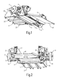
- the rear axle construction shown in figure 1 is then realized.
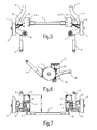
- the conversion kit applied for this purpose comprises substantially a U-shaped carrier body with a beam part 12 between opposite legs 14,16 which are formed integrally therewith or are connected sufficiently firmly thereto, for instance by means of welding or, as in this example, bolts.
- the carrier body serves to restore sufficient strength to the bodywork in lateral direction now that the original bottom has been interrupted at that position.
- this carrier body serves as support for a new loading floor and as new mounting base for wheel suspension.
- this new wheel suspension comprises a pivot arm construction 22,24 and 42,44 respectively with which the associated wheel is connected for pivoting about a pivot axis directed transversely of beam part 12 to an adjacent side of the carrier body.
- the pivot arm construction comprises for both wheels a pair of pivot arms, of which both an upper pivot arm 22,42 and a lower pivot arm 24,44 are coupled for pivoting about a pivot axis directed parallel to a longitudinal axis of the vehicle to the adjacent upright leg of the carrier body.
- the pivot arms of a pair moreover form, together with a further pivoting suspension arm 26,28 of the associated wheel, a triangular bracing which imparts form stiffness and particularly torsional stiffness.
- the further suspension arm 26,28 is connected here for pivoting roughly in the longitudinal direction of the vehicle to the bottom of the vehicle and pivots about a pivot axis oriented roughly parallel to beam part 12.
- both upright legs 14,16 comprise mounting means, in this case in the form of a pair of mounting flanges 17,19, with which the carrier body can be mounted round a pair of opposite tubular profiles (not shown) of the vehicle.
- mounting means in this case in the form of a pair of mounting flanges 17,19, with which the carrier body can be mounted round a pair of opposite tubular profiles (not shown) of the vehicle.
- Serving for this purpose are a pair of bolts and bores provided beforehand for this purpose in flanges 17, 19.
- a disc-like extension 15 is provided on the lower 19 of the two flanges. This lateral part of the relevant flange forms a cheek part corresponding to the position of the original mounting base in the vehicle bottom against which a rubber spring buffer of coil spring 6 was received.
- the carrier body with extensions 15 is placed thereover and placed in line therewith.
- a bore 151 provided for this purpose in extension 15 is precisely in register with a corresponding threaded hole in the original mounting base of the spring buffer.
- a fitting continuous nut and bolt connection for both bores thus not only provides for renewed fixation of the original spring buffer but also for a precise lateral positioning of the further whole, which will therefore also match the other original suspension components of the vehicle which have to be reattached.
- the carrier body serves as carrier for a lowered loading floor.
- the loading floor 32 forms a part of an integral loading platform, for instance of plastic or stainless steel, which in addition comprises a pair of flanks 34,36 and a front upstand. These parts are sized for a close-fitting seamless assembly in the previously cut-away bottom of the vehicle. If desired, a high-quality finishing layer such as a covering can further be arranged thereover.
- a tilting flap 40 is provided on a rear side which can be lowered or raised manually or hydraulically. Owing to the described conversion the loading floor lies a length / of about 30 centimetres lower than an original level thereof with which the vehicle is supplied as standard. In the described make and model of vehicle and in similar vehicles this already provides per se sufficient extra head room, so that a passenger sitting in a wheelchair can be received therein. An original roof height need not therefore be changed for this purpose.
Landscapes
- Engineering & Computer Science (AREA)
- Mechanical Engineering (AREA)
- Body Structure For Vehicles (AREA)
- Vehicle Body Suspensions (AREA)
Applications Claiming Priority (1)
| Application Number | Priority Date | Filing Date | Title |
|---|---|---|---|
| NL2006717A NL2006717C2 (nl) | 2011-05-04 | 2011-05-04 | Voertuig en wielophangingsamenstel. |
Publications (2)
| Publication Number | Publication Date |
|---|---|
| EP2520448A1 true EP2520448A1 (fr) | 2012-11-07 |
| EP2520448B1 EP2520448B1 (fr) | 2014-04-02 |
Family
ID=45926466
Family Applications (1)
| Application Number | Title | Priority Date | Filing Date |
|---|---|---|---|
| EP12163535.3A Not-in-force EP2520448B1 (fr) | 2011-05-04 | 2012-04-10 | Ensemble de véhicule et suspension de roue |
Country Status (2)
| Country | Link |
|---|---|
| EP (1) | EP2520448B1 (fr) |
| NL (1) | NL2006717C2 (fr) |
Cited By (1)
| Publication number | Priority date | Publication date | Assignee | Title |
|---|---|---|---|---|
| CN107531118A (zh) * | 2015-04-20 | 2018-01-02 | 株式会社Fomm | 用于车辆的悬架构造 |
Citations (7)
| Publication number | Priority date | Publication date | Assignee | Title |
|---|---|---|---|---|
| FR2702956A1 (fr) * | 1993-03-25 | 1994-09-30 | Morice Jean Herve Marie | Véhicule automobile facilement accessible à un fauteuil roulant. |
| WO1999030956A1 (fr) * | 1997-12-12 | 1999-06-24 | Holland Neway International, Inc. | Suspension avant independante |
| US6382647B1 (en) * | 2000-05-12 | 2002-05-07 | Rodney D. Smith | Trailer apparatus |
| US20030111834A1 (en) * | 2001-12-12 | 2003-06-19 | Ragnar Ledesma | Independent suspension undercarriage module for a low floor vehicle |
| US20040036266A1 (en) * | 2000-02-23 | 2004-02-26 | Tardini Gian Paolo | Modular frame for transportation vehicle having depressed flatbed |
| US6733021B1 (en) * | 2001-10-26 | 2004-05-11 | Dana Corporation | Vehicle subframe mounting |
| DE102006009300A1 (de) * | 2006-03-01 | 2007-09-06 | Daimlerchrysler Ag | Einzelradaufhängung für eine Hochlenkerachse |
-
2011
- 2011-05-04 NL NL2006717A patent/NL2006717C2/nl not_active IP Right Cessation
-
2012
- 2012-04-10 EP EP12163535.3A patent/EP2520448B1/fr not_active Not-in-force
Patent Citations (7)
| Publication number | Priority date | Publication date | Assignee | Title |
|---|---|---|---|---|
| FR2702956A1 (fr) * | 1993-03-25 | 1994-09-30 | Morice Jean Herve Marie | Véhicule automobile facilement accessible à un fauteuil roulant. |
| WO1999030956A1 (fr) * | 1997-12-12 | 1999-06-24 | Holland Neway International, Inc. | Suspension avant independante |
| US20040036266A1 (en) * | 2000-02-23 | 2004-02-26 | Tardini Gian Paolo | Modular frame for transportation vehicle having depressed flatbed |
| US6382647B1 (en) * | 2000-05-12 | 2002-05-07 | Rodney D. Smith | Trailer apparatus |
| US6733021B1 (en) * | 2001-10-26 | 2004-05-11 | Dana Corporation | Vehicle subframe mounting |
| US20030111834A1 (en) * | 2001-12-12 | 2003-06-19 | Ragnar Ledesma | Independent suspension undercarriage module for a low floor vehicle |
| DE102006009300A1 (de) * | 2006-03-01 | 2007-09-06 | Daimlerchrysler Ag | Einzelradaufhängung für eine Hochlenkerachse |
Cited By (2)
| Publication number | Priority date | Publication date | Assignee | Title |
|---|---|---|---|---|
| CN107531118A (zh) * | 2015-04-20 | 2018-01-02 | 株式会社Fomm | 用于车辆的悬架构造 |
| EP3287306A4 (fr) * | 2015-04-20 | 2019-01-16 | Fomm Corporation | Structure de suspension de véhicule |
Also Published As
| Publication number | Publication date |
|---|---|
| NL2006717C2 (nl) | 2012-11-06 |
| EP2520448B1 (fr) | 2014-04-02 |
Similar Documents
| Publication | Publication Date | Title |
|---|---|---|
| US7775535B2 (en) | Suspension subassembly | |
| EP1613491B1 (fr) | Coussin superieur d'ensemble serrage sur essieu et ensemble fixation de ressort pneumatique | |
| US6158750A (en) | Lift axle assembly | |
| AU2004274434B2 (en) | Rigid axle for a vehicle, comprising integrated trailing arms | |
| JP5784509B2 (ja) | 自動車用サスペンション | |
| CN106457939B (zh) | 车辆悬架 | |
| MX2013013873A (es) | Ensamble de valvula de control de altura para sistemas de eje/suspension. | |
| US20020105170A1 (en) | Low profile chassis and suspension | |
| MX2007009614A (es) | Montadura de remolque frontal extendido. | |
| US7841607B2 (en) | Spring beam suspension system | |
| WO2015067104A1 (fr) | Système de suspension à ressort à lames muni d'une structure d'axe de levage de coussin de sécurité gonflable et véhicule possédant celui-ci | |
| US11207934B2 (en) | Vehicle suspension assembly | |
| US8540214B2 (en) | Vehicle lift | |
| AU2020243823B2 (en) | Suspension assembly | |
| US8162335B1 (en) | Raised axle and suspension system | |
| HU212173B (en) | Pneumatical suspension with longitudinal arms | |
| EP2520448B1 (fr) | Ensemble de véhicule et suspension de roue | |
| US20050263987A1 (en) | Low profile chassis and suspension | |
| MXPA06003098A (es) | Atenuador de torsion para riel de bastidor. | |
| US2131083A (en) | Suspension for vehicles | |
| US9340078B2 (en) | Hydraulic equalizing spreader bar with dual spread links | |
| US20100213681A1 (en) | Vehicle suspension system | |
| AU2023336525A1 (en) | Axle structure for a utility vehicle chassis, comprising an axle bridge | |
| AU2023336528A1 (en) | Axle structure for a utility vehicle chassis, comprising an axle bridge | |
| US3014735A (en) | Tandem axle mounting for vehicles |
Legal Events
| Date | Code | Title | Description |
|---|---|---|---|
| PUAI | Public reference made under article 153(3) epc to a published international application that has entered the european phase |
Free format text: ORIGINAL CODE: 0009012 |
|
| AK | Designated contracting states |
Kind code of ref document: A1 Designated state(s): AL AT BE BG CH CY CZ DE DK EE ES FI FR GB GR HR HU IE IS IT LI LT LU LV MC MK MT NL NO PL PT RO RS SE SI SK SM TR |
|
| AX | Request for extension of the european patent |
Extension state: BA ME |
|
| 17P | Request for examination filed |
Effective date: 20130507 |
|
| GRAP | Despatch of communication of intention to grant a patent |
Free format text: ORIGINAL CODE: EPIDOSNIGR1 |
|
| INTG | Intention to grant announced |
Effective date: 20131101 |
|
| GRAS | Grant fee paid |
Free format text: ORIGINAL CODE: EPIDOSNIGR3 |
|
| GRAA | (expected) grant |
Free format text: ORIGINAL CODE: 0009210 |
|
| AK | Designated contracting states |
Kind code of ref document: B1 Designated state(s): AL AT BE BG CH CY CZ DE DK EE ES FI FR GB GR HR HU IE IS IT LI LT LU LV MC MK MT NL NO PL PT RO RS SE SI SK SM TR |
|
| REG | Reference to a national code |
Ref country code: GB Ref legal event code: FG4D |
|
| REG | Reference to a national code |
Ref country code: CH Ref legal event code: EP Ref country code: AT Ref legal event code: REF Ref document number: 659851 Country of ref document: AT Kind code of ref document: T Effective date: 20140415 |
|
| REG | Reference to a national code |
Ref country code: IE Ref legal event code: FG4D |
|
| REG | Reference to a national code |
Ref country code: DE Ref legal event code: R096 Ref document number: 602012001257 Country of ref document: DE Effective date: 20140515 |
|
| REG | Reference to a national code |
Ref country code: NL Ref legal event code: T3 |
|
| REG | Reference to a national code |
Ref country code: AT Ref legal event code: MK05 Ref document number: 659851 Country of ref document: AT Kind code of ref document: T Effective date: 20140402 |
|
| REG | Reference to a national code |
Ref country code: LT Ref legal event code: MG4D |
|
| PG25 | Lapsed in a contracting state [announced via postgrant information from national office to epo] |
Ref country code: CY Free format text: LAPSE BECAUSE OF FAILURE TO SUBMIT A TRANSLATION OF THE DESCRIPTION OR TO PAY THE FEE WITHIN THE PRESCRIBED TIME-LIMIT Effective date: 20140402 Ref country code: GR Free format text: LAPSE BECAUSE OF FAILURE TO SUBMIT A TRANSLATION OF THE DESCRIPTION OR TO PAY THE FEE WITHIN THE PRESCRIBED TIME-LIMIT Effective date: 20140703 Ref country code: CZ Free format text: LAPSE BECAUSE OF FAILURE TO SUBMIT A TRANSLATION OF THE DESCRIPTION OR TO PAY THE FEE WITHIN THE PRESCRIBED TIME-LIMIT Effective date: 20140402 Ref country code: IS Free format text: LAPSE BECAUSE OF FAILURE TO SUBMIT A TRANSLATION OF THE DESCRIPTION OR TO PAY THE FEE WITHIN THE PRESCRIBED TIME-LIMIT Effective date: 20140802 Ref country code: FI Free format text: LAPSE BECAUSE OF FAILURE TO SUBMIT A TRANSLATION OF THE DESCRIPTION OR TO PAY THE FEE WITHIN THE PRESCRIBED TIME-LIMIT Effective date: 20140402 Ref country code: NO Free format text: LAPSE BECAUSE OF FAILURE TO SUBMIT A TRANSLATION OF THE DESCRIPTION OR TO PAY THE FEE WITHIN THE PRESCRIBED TIME-LIMIT Effective date: 20140702 Ref country code: LT Free format text: LAPSE BECAUSE OF FAILURE TO SUBMIT A TRANSLATION OF THE DESCRIPTION OR TO PAY THE FEE WITHIN THE PRESCRIBED TIME-LIMIT Effective date: 20140402 Ref country code: BG Free format text: LAPSE BECAUSE OF FAILURE TO SUBMIT A TRANSLATION OF THE DESCRIPTION OR TO PAY THE FEE WITHIN THE PRESCRIBED TIME-LIMIT Effective date: 20140702 |
|
| PG25 | Lapsed in a contracting state [announced via postgrant information from national office to epo] |
Ref country code: PL Free format text: LAPSE BECAUSE OF FAILURE TO SUBMIT A TRANSLATION OF THE DESCRIPTION OR TO PAY THE FEE WITHIN THE PRESCRIBED TIME-LIMIT Effective date: 20140402 Ref country code: HR Free format text: LAPSE BECAUSE OF FAILURE TO SUBMIT A TRANSLATION OF THE DESCRIPTION OR TO PAY THE FEE WITHIN THE PRESCRIBED TIME-LIMIT Effective date: 20140402 Ref country code: AT Free format text: LAPSE BECAUSE OF FAILURE TO SUBMIT A TRANSLATION OF THE DESCRIPTION OR TO PAY THE FEE WITHIN THE PRESCRIBED TIME-LIMIT Effective date: 20140402 Ref country code: LV Free format text: LAPSE BECAUSE OF FAILURE TO SUBMIT A TRANSLATION OF THE DESCRIPTION OR TO PAY THE FEE WITHIN THE PRESCRIBED TIME-LIMIT Effective date: 20140402 Ref country code: ES Free format text: LAPSE BECAUSE OF FAILURE TO SUBMIT A TRANSLATION OF THE DESCRIPTION OR TO PAY THE FEE WITHIN THE PRESCRIBED TIME-LIMIT Effective date: 20140402 Ref country code: SE Free format text: LAPSE BECAUSE OF FAILURE TO SUBMIT A TRANSLATION OF THE DESCRIPTION OR TO PAY THE FEE WITHIN THE PRESCRIBED TIME-LIMIT Effective date: 20140402 Ref country code: RS Free format text: LAPSE BECAUSE OF FAILURE TO SUBMIT A TRANSLATION OF THE DESCRIPTION OR TO PAY THE FEE WITHIN THE PRESCRIBED TIME-LIMIT Effective date: 20140402 |
|
| PG25 | Lapsed in a contracting state [announced via postgrant information from national office to epo] |
Ref country code: PT Free format text: LAPSE BECAUSE OF FAILURE TO SUBMIT A TRANSLATION OF THE DESCRIPTION OR TO PAY THE FEE WITHIN THE PRESCRIBED TIME-LIMIT Effective date: 20140804 |
|
| REG | Reference to a national code |
Ref country code: DE Ref legal event code: R097 Ref document number: 602012001257 Country of ref document: DE |
|
| REG | Reference to a national code |
Ref country code: IE Ref legal event code: MM4A |
|
| PG25 | Lapsed in a contracting state [announced via postgrant information from national office to epo] |
Ref country code: SK Free format text: LAPSE BECAUSE OF FAILURE TO SUBMIT A TRANSLATION OF THE DESCRIPTION OR TO PAY THE FEE WITHIN THE PRESCRIBED TIME-LIMIT Effective date: 20140402 Ref country code: MC Free format text: LAPSE BECAUSE OF FAILURE TO SUBMIT A TRANSLATION OF THE DESCRIPTION OR TO PAY THE FEE WITHIN THE PRESCRIBED TIME-LIMIT Effective date: 20140402 Ref country code: EE Free format text: LAPSE BECAUSE OF FAILURE TO SUBMIT A TRANSLATION OF THE DESCRIPTION OR TO PAY THE FEE WITHIN THE PRESCRIBED TIME-LIMIT Effective date: 20140402 Ref country code: DK Free format text: LAPSE BECAUSE OF FAILURE TO SUBMIT A TRANSLATION OF THE DESCRIPTION OR TO PAY THE FEE WITHIN THE PRESCRIBED TIME-LIMIT Effective date: 20140402 Ref country code: RO Free format text: LAPSE BECAUSE OF FAILURE TO SUBMIT A TRANSLATION OF THE DESCRIPTION OR TO PAY THE FEE WITHIN THE PRESCRIBED TIME-LIMIT Effective date: 20140402 |
|
| PLBE | No opposition filed within time limit |
Free format text: ORIGINAL CODE: 0009261 |
|
| STAA | Information on the status of an ep patent application or granted ep patent |
Free format text: STATUS: NO OPPOSITION FILED WITHIN TIME LIMIT |
|
| 26N | No opposition filed |
Effective date: 20150106 |
|
| PG25 | Lapsed in a contracting state [announced via postgrant information from national office to epo] |
Ref country code: IT Free format text: LAPSE BECAUSE OF FAILURE TO SUBMIT A TRANSLATION OF THE DESCRIPTION OR TO PAY THE FEE WITHIN THE PRESCRIBED TIME-LIMIT Effective date: 20140402 |
|
| REG | Reference to a national code |
Ref country code: DE Ref legal event code: R097 Ref document number: 602012001257 Country of ref document: DE Effective date: 20150106 |
|
| REG | Reference to a national code |
Ref country code: FR Ref legal event code: PLFP Year of fee payment: 4 |
|
| PG25 | Lapsed in a contracting state [announced via postgrant information from national office to epo] |
Ref country code: IE Free format text: LAPSE BECAUSE OF NON-PAYMENT OF DUE FEES Effective date: 20140410 |
|
| PG25 | Lapsed in a contracting state [announced via postgrant information from national office to epo] |
Ref country code: RS Free format text: LAPSE BECAUSE OF FAILURE TO SUBMIT A TRANSLATION OF THE DESCRIPTION OR TO PAY THE FEE WITHIN THE PRESCRIBED TIME-LIMIT Effective date: 20141119 |
|
| PG25 | Lapsed in a contracting state [announced via postgrant information from national office to epo] |
Ref country code: SI Free format text: LAPSE BECAUSE OF FAILURE TO SUBMIT A TRANSLATION OF THE DESCRIPTION OR TO PAY THE FEE WITHIN THE PRESCRIBED TIME-LIMIT Effective date: 20140402 |
|
| PGFP | Annual fee paid to national office [announced via postgrant information from national office to epo] |
Ref country code: DE Payment date: 20150421 Year of fee payment: 4 |
|
| PGFP | Annual fee paid to national office [announced via postgrant information from national office to epo] |
Ref country code: FR Payment date: 20150421 Year of fee payment: 4 Ref country code: NL Payment date: 20150430 Year of fee payment: 4 Ref country code: BE Payment date: 20150427 Year of fee payment: 4 |
|
| REG | Reference to a national code |
Ref country code: CH Ref legal event code: PL |
|
| PG25 | Lapsed in a contracting state [announced via postgrant information from national office to epo] |
Ref country code: LI Free format text: LAPSE BECAUSE OF NON-PAYMENT OF DUE FEES Effective date: 20150430 Ref country code: CH Free format text: LAPSE BECAUSE OF NON-PAYMENT OF DUE FEES Effective date: 20150430 |
|
| PG25 | Lapsed in a contracting state [announced via postgrant information from national office to epo] |
Ref country code: MT Free format text: LAPSE BECAUSE OF FAILURE TO SUBMIT A TRANSLATION OF THE DESCRIPTION OR TO PAY THE FEE WITHIN THE PRESCRIBED TIME-LIMIT Effective date: 20140402 |
|
| PG25 | Lapsed in a contracting state [announced via postgrant information from national office to epo] |
Ref country code: SM Free format text: LAPSE BECAUSE OF FAILURE TO SUBMIT A TRANSLATION OF THE DESCRIPTION OR TO PAY THE FEE WITHIN THE PRESCRIBED TIME-LIMIT Effective date: 20140402 |
|
| PG25 | Lapsed in a contracting state [announced via postgrant information from national office to epo] |
Ref country code: TR Free format text: LAPSE BECAUSE OF FAILURE TO SUBMIT A TRANSLATION OF THE DESCRIPTION OR TO PAY THE FEE WITHIN THE PRESCRIBED TIME-LIMIT Effective date: 20140402 Ref country code: HU Free format text: LAPSE BECAUSE OF FAILURE TO SUBMIT A TRANSLATION OF THE DESCRIPTION OR TO PAY THE FEE WITHIN THE PRESCRIBED TIME-LIMIT; INVALID AB INITIO Effective date: 20120410 Ref country code: LU Free format text: LAPSE BECAUSE OF NON-PAYMENT OF DUE FEES Effective date: 20140410 |
|
| PG25 | Lapsed in a contracting state [announced via postgrant information from national office to epo] |
Ref country code: BE Free format text: LAPSE BECAUSE OF NON-PAYMENT OF DUE FEES Effective date: 20160430 |
|
| REG | Reference to a national code |
Ref country code: DE Ref legal event code: R119 Ref document number: 602012001257 Country of ref document: DE |
|
| REG | Reference to a national code |
Ref country code: NL Ref legal event code: MM Effective date: 20160501 |
|
| GBPC | Gb: european patent ceased through non-payment of renewal fee |
Effective date: 20160410 |
|
| REG | Reference to a national code |
Ref country code: FR Ref legal event code: ST Effective date: 20161230 |
|
| PG25 | Lapsed in a contracting state [announced via postgrant information from national office to epo] |
Ref country code: NL Free format text: LAPSE BECAUSE OF NON-PAYMENT OF DUE FEES Effective date: 20160501 Ref country code: FR Free format text: LAPSE BECAUSE OF NON-PAYMENT OF DUE FEES Effective date: 20160502 Ref country code: GB Free format text: LAPSE BECAUSE OF NON-PAYMENT OF DUE FEES Effective date: 20160410 Ref country code: DE Free format text: LAPSE BECAUSE OF NON-PAYMENT OF DUE FEES Effective date: 20161101 |
|
| PG25 | Lapsed in a contracting state [announced via postgrant information from national office to epo] |
Ref country code: MK Free format text: LAPSE BECAUSE OF FAILURE TO SUBMIT A TRANSLATION OF THE DESCRIPTION OR TO PAY THE FEE WITHIN THE PRESCRIBED TIME-LIMIT Effective date: 20140402 |
|
| PG25 | Lapsed in a contracting state [announced via postgrant information from national office to epo] |
Ref country code: AL Free format text: LAPSE BECAUSE OF FAILURE TO SUBMIT A TRANSLATION OF THE DESCRIPTION OR TO PAY THE FEE WITHIN THE PRESCRIBED TIME-LIMIT Effective date: 20140402 |