EP2520524A1 - Système de transfer pour le transfer de produits entre deux lignes de convoyage parallèles - Google Patents
Système de transfer pour le transfer de produits entre deux lignes de convoyage parallèles Download PDFInfo
- Publication number
- EP2520524A1 EP2520524A1 EP12167028A EP12167028A EP2520524A1 EP 2520524 A1 EP2520524 A1 EP 2520524A1 EP 12167028 A EP12167028 A EP 12167028A EP 12167028 A EP12167028 A EP 12167028A EP 2520524 A1 EP2520524 A1 EP 2520524A1
- Authority
- EP
- European Patent Office
- Prior art keywords
- robots
- products
- buffer
- transfer system
- compartments
- Prior art date
- Legal status (The legal status is an assumption and is not a legal conclusion. Google has not performed a legal analysis and makes no representation as to the accuracy of the status listed.)
- Granted
Links
Images
Classifications
-
- B—PERFORMING OPERATIONS; TRANSPORTING
- B65—CONVEYING; PACKING; STORING; HANDLING THIN OR FILAMENTARY MATERIAL
- B65G—TRANSPORT OR STORAGE DEVICES, e.g. CONVEYORS FOR LOADING OR TIPPING, SHOP CONVEYOR SYSTEMS OR PNEUMATIC TUBE CONVEYORS
- B65G61/00—Use of pick-up or transfer devices or of manipulators for stacking or de-stacking articles not otherwise provided for
-
- B—PERFORMING OPERATIONS; TRANSPORTING
- B65—CONVEYING; PACKING; STORING; HANDLING THIN OR FILAMENTARY MATERIAL
- B65G—TRANSPORT OR STORAGE DEVICES, e.g. CONVEYORS FOR LOADING OR TIPPING, SHOP CONVEYOR SYSTEMS OR PNEUMATIC TUBE CONVEYORS
- B65G47/00—Article or material-handling devices associated with conveyors; Methods employing such devices
- B65G47/22—Devices influencing the relative position or the attitude of articles during transit by conveyors
- B65G47/24—Devices influencing the relative position or the attitude of articles during transit by conveyors orientating the articles
-
- B—PERFORMING OPERATIONS; TRANSPORTING
- B65—CONVEYING; PACKING; STORING; HANDLING THIN OR FILAMENTARY MATERIAL
- B65G—TRANSPORT OR STORAGE DEVICES, e.g. CONVEYORS FOR LOADING OR TIPPING, SHOP CONVEYOR SYSTEMS OR PNEUMATIC TUBE CONVEYORS
- B65G47/00—Article or material-handling devices associated with conveyors; Methods employing such devices
- B65G47/34—Devices for discharging articles or materials from conveyor
- B65G47/46—Devices for discharging articles or materials from conveyor and distributing, e.g. automatically, to desired points
- B65G47/51—Devices for discharging articles or materials from conveyor and distributing, e.g. automatically, to desired points according to unprogrammed signals, e.g. influenced by supply situation at destination
- B65G47/5104—Devices for discharging articles or materials from conveyor and distributing, e.g. automatically, to desired points according to unprogrammed signals, e.g. influenced by supply situation at destination for articles
-
- B—PERFORMING OPERATIONS; TRANSPORTING
- B65—CONVEYING; PACKING; STORING; HANDLING THIN OR FILAMENTARY MATERIAL
- B65G—TRANSPORT OR STORAGE DEVICES, e.g. CONVEYORS FOR LOADING OR TIPPING, SHOP CONVEYOR SYSTEMS OR PNEUMATIC TUBE CONVEYORS
- B65G47/00—Article or material-handling devices associated with conveyors; Methods employing such devices
- B65G47/52—Devices for transferring articles or materials between conveyors i.e. discharging or feeding devices
-
- B—PERFORMING OPERATIONS; TRANSPORTING
- B65—CONVEYING; PACKING; STORING; HANDLING THIN OR FILAMENTARY MATERIAL
- B65B—MACHINES, APPARATUS OR DEVICES FOR, OR METHODS OF, PACKAGING ARTICLES OR MATERIALS; UNPACKING
- B65B5/00—Packaging individual articles in containers or receptacles, e.g. bags, sacks, boxes, cartons, cans, jars
- B65B5/10—Filling containers or receptacles progressively or in stages by introducing successive articles, or layers of articles
- B65B5/105—Filling containers or receptacles progressively or in stages by introducing successive articles, or layers of articles by grippers
Definitions
- the present invention relates to a transfer system for transferring products between two parallel transport lines by means of a series of robots.
- Packaging systems are known, in which a belt transports randomly arranged products parallel to a conveyor, which transports a series of spaced compartments at a constant pace.
- the products are picked up and then deposited in the compartments by means of at least two robots, arranged in a row one after the other along the feeding direction of the belt and above the belt itself.
- the packaging system is provided with a vision system which is arranged upstream of the row of robots, determines the positions of the incoming products and communicates information relative to said positions to one or more control units associated with the robots.
- the speed of the compartments is set according to the rate of incoming products, but effectively the number of products oscillates greatly over time and depends on the method with which the products are unloaded onto the belt upstream of the robots.
- the last robot in the row is configured so as to attempt to fill any compartments which were not filled by the preceding robots. If the compartments and the products travel in the same direction, the last robot sometimes does not have available products on the belt, as they have already been picked up by the preceding robots. To avoid the exit of empty compartments, usually the speed of the conveyor transporting the compartments is temporarily reduced. By doing so, however, the robots at the beginning of the row tend to fill the compartments more than necessary: in other words, an opposite situation tends to develop, in which the last robot does not find empty compartments in which to put the products arriving at the end of the belt. In this situation, in order to avoid these excess products to exit and be discarded, there is the tendency to speed up again the conveyor transporting the compartments.
- the object of the present invention is to provide a transfer system for transferring products between two parallel transport lines by means of a series of robots, which allows the above-mentioned requirement to be fulfilled in a simple and cost-effective manner.
- a transfer system for transferring products between two parallel transport lines by means of a series of robots, as defined in claim 1.
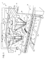
- the numeral 1 indicates, as a whole, a transfer system (partially shown) for inserting products 2 into respective compartments 3 by means of a series of robots 4, which are controlled by respective processing and control units 4a on the basis of information provided by a vision system 5.
- a vision system 5 a vision system 5.
- figure 1 shows a cell with two robots 4, but there could be a greater number of robots and/or cells.
- the products 2 are deposited or unloaded randomly, i.e. in random positions, on the upper surface of a conveyor belt 6 by means of a production, transport, sorting or unloading system (not shown), at the beginning of the path defined by said belt 6.
- the products 2 may be of the same type or different types: in the latter case, the compartments 3 may be filled with different types of products or with the same type of products.
- Belt 6 is driven by an electric motor (not shown) in order to move the products 2 along a rectilinear direction A, preferably at a constant speed, under the control of a central processing and control unit 12, separated by the units 4a.
- the compartments 3 are transported parallel to direction A and in fixed relative positions by a conveyor 13, for example a chain conveyor, which is arranged side by side with belt 6.
- a conveyor 13 is motorized so as to move the row of compartments 3 in the same direction as the products 2, in particular towards a packaging machine (not shown).
- the compartments 3 may be moved in counter-flow with respect to the products 2; and/or two conveyors parallel to belt 6 may be provided , having the same speed or different speeds and/or different directions.
- compartments 3 are defined by boxes or trays carried by conveyor 13, or by housings provided directly on conveyor 13.
- Each compartment 3 may have dimensions such as to house a single product 2, or may have greater dimensions so as to house a plurality of products 2.
- the speed of conveyor 13 is set at a constant value which is a function of the rate of incoming products 2 and is such so as to avoid the discarding of products 2 at the end of belt 6.
- the rate of incoming products has a substantially constant average component and an oscillating component, which depend on the system arranged upstream of belt 6.
- the robots 4 are substantially arranged in a row along direction A, comprising respective gripping members 15, defined by suckers or pincers, and define respective working fields 16, in which the gripping members 15 can arrive and operate, i.e. go and pick up and go and deposit the products 2.
- the size of each working field 16 depends on the movement capacity of the robot 4, i.e. its the dimensional and constructional characteristics and its degrees of freedom.
- the robots 4 are of the type commonly known as delta-robots, whereby each one has a working field 16 which is substantially cylindrical with a vertical central axis.
- the robots 4 are arranged above belt 6 and conveyor 13 and are suspended from one or more support structures 19.
- structure 19 (partially shown) is of the cell type and carries two robots 4.
- Vision system 5 comprises at least one video camera (or a camera) and a data processing unit, which processes the images from the video camera, determines the position, the orientation and the number of products 2 passing in area 18 and communicates the corresponding information at least to unit 4a of the first robot 4 (considering the feeding direction of the products 2 along direction A).
- Said first robot 4 distributes the data of the products 2 which it is not able to pick up to the subsequent robots 4. Each robot 4 will tend to pick up and deposit the maximum number of products 2.
- System 1 further comprises a buffer, or magazine, or parking area, which is indicated by the reference number 21 and defines a horizontal supporting surface having one or more places available, in order to have the possibility to temporarily park respective products 2, before depositing them in the compartments 3.
- a buffer, or magazine, or parking area which is indicated by the reference number 21 and defines a horizontal supporting surface having one or more places available, in order to have the possibility to temporarily park respective products 2, before depositing them in the compartments 3.
- buffer 21 is arranged above belt 6 and/or conveyor 13, at a sufficient height to allow the products 2 to pass below, and in an intermediate or boundary area between two adjacent robots 4, which both have access to the same places on the buffer 21, both for picking up and depositing products 2.
- Buffer 21 is therefore aligned with the robots 4 along direction A, but is preferably elongated in a horizontal direction C which is orthogonal to direction A, so as to define a plurality of available places which are side by side along direction C.
- buffer 21 is only arranged above belt 6 and is fixed to a structure which supports belt 6.
- buffer 21 preferably extends for the whole width of belt 6 and conveyor 13 and is supported, at the ends thereof, by two lateral uprights 22 of structure 19.
- position sensors or additional vision systems can be provided in order to determine the position and/or orientation of the products 2 on buffer 21 and therefore communicate the corresponding information to the units 4a, so as to increase the precision of the operations of picking up products 2 from buffer 21.
- Such sensors are not strictly necessary in all those cases in which the precision required is not critical.
- buffer 21 is within both the working fields 16 and is preferably kept in a fixed position along direction A.
- the working fields 16 intersect at the boundary area between the two adjacent robots 4, whereby a space 23 exists which is shared by both working fields 16 and which houses the available places of buffer 21.
- the robots 4 both have access to buffer 21, but unit 12 is configured so as to prevent the two robots 4 having contemporary access to space 23 and therefore colliding with each other.
- Unit 12 manages the authorizations for access to shared space 23 communicating with both the units 4a, and has a block indicator which is active or deactivated so as to indicate to the units 4a if space 23 is occupied or free, respectively.
- the latter sends an access request to unit 12 in order to verify the state of the aforementioned lock indicator and therefore establish if space 23 is occupied.
- unit 12 sends an explicit consent response to unit 4a, and the latter sends a corresponding signal to unit 12 in order to activate the lock indicator. In this way, if the other unit 4a sends an access request to unit 12, it finds the lock indicator to be active and does not receive consent to enter space 23.
- robot 4 exits from space 23 and the corresponding unit 4a sends a signal to unit 12 which indicates the conclusion of the operation and deactivates the aforementioned lock indicator, so that subsequent access requests can be satisfied.
- a presence detection system and/or a position detection system for example of the video camera type, is provided in order to determine if any of the two robots 4 approaches space 23 and/or engages space 23.
- Said system sends a relative lock signal to unit 12 and/or to unit 4a of the other robot 4, in order to prevent that the latter also accesses space 23.
- unit 12 receives two simultaneous access requests, it is configured to give access priority to robot 4 which is upstream, considering the feeding direction of the products 2 on belt 6.
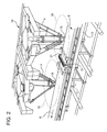
- the working fields 16 are distinct, or space 23 is too small to house all the available places on buffer 21: in order to obviate this drawback and ensure that the places on buffer 21 can be reached by both robots 4, buffer 21 is movable along direction A of a relatively short travel D (for example of around 20 cm) under the action of an actuator assembly (not shown). Said actuator assembly is controlled by units 12 and/or 4a, so as to move buffer 21 between two operative positions, in which buffer 21 is selectively within one and the other of the working fields 16, respectively. Buffer 21 is synchronously actuated with the picking up and depositing movements carried out by the robots 4, so as to serve one or the other of the two robots 4 according to necessity. In other words, buffer 21 operates as a shuttle equipped with non-uniform alternating motion, to ensure that the robots 4 both have access to the available places on buffer 21.
- the units 4a communicate with each other in order to know which products 2 have remained on belt 6 and which free compartments 3 have remained after the cycles carried out by the other robots 4 ("cycle" means a picking up movement and a depositing movement together), while vision system 5 distributes the data relative to the various incoming products 2 to the various units 4a.
- the units 4a calculate the instantaneous positions of the products 2 using the relative positions of the products 2 provided by vision system 5 and using the speed of the products 2 along direction A (which is calculated, preferably, according to the rotation angle of the electric motor of belt 6, measured by a position transducer, encoder or resolver).
- Units 4a and/or 12 can also regulate the operating rhythm of each robot 4, i.e. the number of cycles in the unit of time, according to the average rate of incoming products.
- cycle n° 1 pick up at least one product 2 from belt 6 and deposit it in buffer 21
- cycle n° 2 pick up at least one product 2 from belt 6 and deposit it in a compartment 3
- cycle n° 3 pick up at least one product 2 from buffer 21 and deposit it in a free compartment 3.
- a safety check is provided, which stops conveyor 13 if there are any compartments 3 which are at least partially empty as they exit system 1, so as to give the last robot 4 time to terminate the filling.
- the packaging machine arranged after conveyor 13 is also stopped. Said situation occurs occasionally, in the event of an error in depositing a product 2, or the damaging of a product 2, or variations in flow which are too high to be compensated by buffer 21.
- the available places of buffer 21 can be used for picking up and/or depositing by both the adjacent robots 4, whereby the operation of system 1 is extremely flexible.
- the products 2 can even be caused to go back, i.e. transferred in the opposite direction with respect to the exit of belt 6, e.g. in order to obviate a shortage of incoming products 2 on belt 6.
- the position of buffer 21 above belt 6 and/or conveyor 13 is extremely advantageous for reducing dimensions, considering that nothing is provided at the sides of the transport lines, which are defined by belt 6 and conveyor 13.
- the embodiment in figure 1 is constructively very simple, due to the fact that it is not necessary to move buffer 21 along direction A, but only to programme the units 4a so as to prevent interference between the robots 4 in space 23.
- the product transport line could be constituted by one or more belts arranged in succession along direction A and dragged independently of each other in order to eliminate possible empty spaces between groups of products if necessary.
- vision system 5 could comprise one or more additional video cameras, arranged, for example, in the boundary areas between the working fields 16 of the robots 4.
- the gripping members 15 could each have two or more suckers, so as to pick up several products, one after the other, before depositing them on buffer 21 or in the compartments 3.
- Vision system 5 could be replaced by a system of sensors different from the video cameras for determining the position of the products on belt 6.
Landscapes
- Engineering & Computer Science (AREA)
- Mechanical Engineering (AREA)
- Manipulator (AREA)
- Warehouses Or Storage Devices (AREA)
- Container, Conveyance, Adherence, Positioning, Of Wafer (AREA)
Applications Claiming Priority (1)
| Application Number | Priority Date | Filing Date | Title |
|---|---|---|---|
| IT000405A ITTO20110405A1 (it) | 2011-05-06 | 2011-05-06 | Impianto di trasferimento per trasferire prodotti tra due linee di trasporto parallele tramite una serie di robot |
Publications (2)
| Publication Number | Publication Date |
|---|---|
| EP2520524A1 true EP2520524A1 (fr) | 2012-11-07 |
| EP2520524B1 EP2520524B1 (fr) | 2015-04-01 |
Family
ID=44554386
Family Applications (1)
| Application Number | Title | Priority Date | Filing Date |
|---|---|---|---|
| EP12167028.5A Active EP2520524B1 (fr) | 2011-05-06 | 2012-05-07 | Système de transfer pour le transfer de produits entre deux lignes de convoyage parallèles |
Country Status (2)
| Country | Link |
|---|---|
| EP (1) | EP2520524B1 (fr) |
| IT (1) | ITTO20110405A1 (fr) |
Cited By (12)
| Publication number | Priority date | Publication date | Assignee | Title |
|---|---|---|---|---|
| WO2015118171A1 (fr) * | 2014-02-10 | 2015-08-13 | Ocado Innovation Limited | Installation de stockage intermédiaire pour poste de préparation de commandes |
| GB2536805A (en) * | 2015-03-18 | 2016-09-28 | Ishida Seisakusho | Article accumulating device |
| CN106516228A (zh) * | 2016-12-13 | 2017-03-22 | 广州中国科学院先进技术研究所 | 一种基于机器人的包子分装线系统 |
| JP2017056528A (ja) * | 2015-09-17 | 2017-03-23 | 株式会社安川電機 | 移送システムおよび移送方法 |
| JP2017056529A (ja) * | 2015-09-17 | 2017-03-23 | 株式会社安川電機 | 移送システムおよび移送方法 |
| CN107176432A (zh) * | 2017-06-15 | 2017-09-19 | 西安科技大学 | 一种基于机器视觉的锚杆异物及皮带撕裂检测系统 |
| CN107720274A (zh) * | 2017-11-06 | 2018-02-23 | 苏州展德自动化设备有限公司 | 陶瓷基板的转运设备 |
| CN108033063A (zh) * | 2017-12-15 | 2018-05-15 | 深圳市海科瑞科技有限公司 | 一种基于视觉系统的杯装食品自动装盘设备及方法 |
| ES2741509A1 (es) * | 2018-08-08 | 2020-02-11 | Valles Tomas Mulet | Dispositivo de sujecion de objetos para pistas de transferencia y maquina para manipular objetos asociada al mismo |
| CN110860487A (zh) * | 2019-11-22 | 2020-03-06 | 山东新华医疗器械股份有限公司 | 一种自动装料系统 |
| IT201900025165A1 (it) * | 2019-12-20 | 2021-06-20 | Atlanta Stretch S P A | Sistema di movimentazione fornito di una stazione per rilevare posizione e dimensioni di un oggetto in movimentazione |
| WO2024254391A1 (fr) * | 2023-06-09 | 2024-12-12 | Berkshire Grey Operating Company, Inc. | Systèmes et procédés de traitement dynamique d'objets à l'aide de caches de stockage intermédiaires |
Families Citing this family (1)
| Publication number | Priority date | Publication date | Assignee | Title |
|---|---|---|---|---|
| CN112809725B (zh) * | 2020-12-30 | 2022-04-01 | 创维集团智能装备有限公司 | 一种注塑流水线定位抓取设备 |
Citations (5)
| Publication number | Priority date | Publication date | Assignee | Title |
|---|---|---|---|---|
| WO1995035238A1 (fr) * | 1994-06-17 | 1995-12-28 | Scanvaegt A/S | Procede et systeme pour former des portions pesees d'articles alimentaires disposes suivant un certain ordre |
| US6011998A (en) * | 1997-05-09 | 2000-01-04 | Lichti; Wayne | High speed picking system |
| WO2006061024A1 (fr) * | 2004-12-10 | 2006-06-15 | Scanvaegt International A/S | Procede et systeme d'etablissement de lots d'objets |
| WO2010022832A1 (fr) * | 2008-08-29 | 2010-03-04 | SSI Schäfer PEEM GmbH | Procédé et dispositif de préparation d’articles entièrement automatique et sans opérateur, dans des moyens d’aide au chargement des commandes |
| EP2233400A1 (fr) | 2009-03-25 | 2010-09-29 | OPM S.p.A. | Procédé et dispositif d'emballage |
-
2011
- 2011-05-06 IT IT000405A patent/ITTO20110405A1/it unknown
-
2012
- 2012-05-07 EP EP12167028.5A patent/EP2520524B1/fr active Active
Patent Citations (5)
| Publication number | Priority date | Publication date | Assignee | Title |
|---|---|---|---|---|
| WO1995035238A1 (fr) * | 1994-06-17 | 1995-12-28 | Scanvaegt A/S | Procede et systeme pour former des portions pesees d'articles alimentaires disposes suivant un certain ordre |
| US6011998A (en) * | 1997-05-09 | 2000-01-04 | Lichti; Wayne | High speed picking system |
| WO2006061024A1 (fr) * | 2004-12-10 | 2006-06-15 | Scanvaegt International A/S | Procede et systeme d'etablissement de lots d'objets |
| WO2010022832A1 (fr) * | 2008-08-29 | 2010-03-04 | SSI Schäfer PEEM GmbH | Procédé et dispositif de préparation d’articles entièrement automatique et sans opérateur, dans des moyens d’aide au chargement des commandes |
| EP2233400A1 (fr) | 2009-03-25 | 2010-09-29 | OPM S.p.A. | Procédé et dispositif d'emballage |
Cited By (18)
| Publication number | Priority date | Publication date | Assignee | Title |
|---|---|---|---|---|
| EP3137400B1 (fr) | 2014-02-10 | 2024-10-09 | Ocado Innovation Limited | Installation de stockage intermédiaire pour poste de préparation de commandes |
| CN106794946A (zh) * | 2014-02-10 | 2017-05-31 | 奥卡多创新有限公司 | 拣选站中间存放设备 |
| WO2015118171A1 (fr) * | 2014-02-10 | 2015-08-13 | Ocado Innovation Limited | Installation de stockage intermédiaire pour poste de préparation de commandes |
| GB2536805A (en) * | 2015-03-18 | 2016-09-28 | Ishida Seisakusho | Article accumulating device |
| GB2536805B (en) * | 2015-03-18 | 2019-01-16 | Ishida Seisakusho | Method of controlling an article accumulating device |
| JP2017056528A (ja) * | 2015-09-17 | 2017-03-23 | 株式会社安川電機 | 移送システムおよび移送方法 |
| JP2017056529A (ja) * | 2015-09-17 | 2017-03-23 | 株式会社安川電機 | 移送システムおよび移送方法 |
| CN106516228A (zh) * | 2016-12-13 | 2017-03-22 | 广州中国科学院先进技术研究所 | 一种基于机器人的包子分装线系统 |
| CN106516228B (zh) * | 2016-12-13 | 2019-09-10 | 广州中国科学院先进技术研究所 | 一种基于机器人的包子分装线系统 |
| CN107176432A (zh) * | 2017-06-15 | 2017-09-19 | 西安科技大学 | 一种基于机器视觉的锚杆异物及皮带撕裂检测系统 |
| CN107176432B (zh) * | 2017-06-15 | 2019-03-22 | 西安科技大学 | 一种基于机器视觉的锚杆异物及皮带撕裂检测系统 |
| CN107720274A (zh) * | 2017-11-06 | 2018-02-23 | 苏州展德自动化设备有限公司 | 陶瓷基板的转运设备 |
| CN108033063A (zh) * | 2017-12-15 | 2018-05-15 | 深圳市海科瑞科技有限公司 | 一种基于视觉系统的杯装食品自动装盘设备及方法 |
| ES2741509A1 (es) * | 2018-08-08 | 2020-02-11 | Valles Tomas Mulet | Dispositivo de sujecion de objetos para pistas de transferencia y maquina para manipular objetos asociada al mismo |
| CN110860487A (zh) * | 2019-11-22 | 2020-03-06 | 山东新华医疗器械股份有限公司 | 一种自动装料系统 |
| CN110860487B (zh) * | 2019-11-22 | 2024-04-12 | 山东新华医疗器械股份有限公司 | 一种自动装料系统 |
| IT201900025165A1 (it) * | 2019-12-20 | 2021-06-20 | Atlanta Stretch S P A | Sistema di movimentazione fornito di una stazione per rilevare posizione e dimensioni di un oggetto in movimentazione |
| WO2024254391A1 (fr) * | 2023-06-09 | 2024-12-12 | Berkshire Grey Operating Company, Inc. | Systèmes et procédés de traitement dynamique d'objets à l'aide de caches de stockage intermédiaires |
Also Published As
| Publication number | Publication date |
|---|---|
| EP2520524B1 (fr) | 2015-04-01 |
| ITTO20110405A1 (it) | 2012-11-07 |
Similar Documents
| Publication | Publication Date | Title |
|---|---|---|
| EP2520524B1 (fr) | Système de transfer pour le transfer de produits entre deux lignes de convoyage parallèles | |
| EP2233400B1 (fr) | Procédé et dispositif d'emballage | |
| JP6514316B2 (ja) | 搬送装置 | |
| JP5504821B2 (ja) | 容器搬送装置 | |
| JP2023030211A (ja) | 貯蔵システム | |
| US9908646B2 (en) | Method and apparatus for placing products into containers in a robot line | |
| EP3700844B1 (fr) | Appareil de disposition en ordre de contenants agencés de manière aléatoire comprenant des moyens d'extraction indépendants les uns des autres | |
| EP3402731B1 (fr) | Système de stockage pour stocker et transporter des casiers | |
| US10232407B2 (en) | Installation for separating and singulating non-uniform postal articles | |
| US6901726B2 (en) | Method and apparatus for putting piece goods into containers | |
| JP5819618B2 (ja) | ワーク移載システム | |
| US20150134110A1 (en) | Robot system and article transfer method | |
| JP2025041811A (ja) | 自動保管・回収システムを動作させる方法 | |
| US20210024298A1 (en) | Picking station and method for automatic picking of goods | |
| WO2017154230A1 (fr) | Système de transporteurs accumulateurs et système de transport | |
| AU2019370900A1 (en) | Storage device for storing transport units | |
| CN107792655B (zh) | 工件取出系统 | |
| CN109807068A (zh) | 分拣装置和分拣方法 | |
| US20230331475A1 (en) | Method for operating a storage facility without lifts | |
| JP3240466B2 (ja) | 包装機等の処理機械への物品供給装置 | |
| US8991586B2 (en) | High-speed storage | |
| CN115815131A (zh) | 摆轮分拣系统的包裹间距调整方法、系统、控制装置及计算机可读存储介质 | |
| CN212711776U (zh) | 一种码包装置 | |
| JP6610881B2 (ja) | 物品処理装置 | |
| EP1460007A1 (fr) | Dispositif de transport d'articles, en particulier pour une machine d'emballage automatique, et méthode d'utilisation correspondante |
Legal Events
| Date | Code | Title | Description |
|---|---|---|---|
| PUAI | Public reference made under article 153(3) epc to a published international application that has entered the european phase |
Free format text: ORIGINAL CODE: 0009012 |
|
| AK | Designated contracting states |
Kind code of ref document: A1 Designated state(s): AL AT BE BG CH CY CZ DE DK EE ES FI FR GB GR HR HU IE IS IT LI LT LU LV MC MK MT NL NO PL PT RO RS SE SI SK SM TR |
|
| AX | Request for extension of the european patent |
Extension state: BA ME |
|
| RAP1 | Party data changed (applicant data changed or rights of an application transferred) |
Owner name: CARLE & MONTANARI - OPM S.P.A. |
|
| 17P | Request for examination filed |
Effective date: 20130507 |
|
| 17Q | First examination report despatched |
Effective date: 20131127 |
|
| GRAP | Despatch of communication of intention to grant a patent |
Free format text: ORIGINAL CODE: EPIDOSNIGR1 |
|
| INTG | Intention to grant announced |
Effective date: 20141016 |
|
| GRAS | Grant fee paid |
Free format text: ORIGINAL CODE: EPIDOSNIGR3 |
|
| GRAA | (expected) grant |
Free format text: ORIGINAL CODE: 0009210 |
|
| AK | Designated contracting states |
Kind code of ref document: B1 Designated state(s): AL AT BE BG CH CY CZ DE DK EE ES FI FR GB GR HR HU IE IS IT LI LT LU LV MC MK MT NL NO PL PT RO RS SE SI SK SM TR |
|
| REG | Reference to a national code |
Ref country code: GB Ref legal event code: FG4D |
|
| REG | Reference to a national code |
Ref country code: CH Ref legal event code: EP |
|
| REG | Reference to a national code |
Ref country code: IE Ref legal event code: FG4D |
|
| REG | Reference to a national code |
Ref country code: CH Ref legal event code: NV Representative=s name: ANDRE ROLAND S.A., CH |
|
| REG | Reference to a national code |
Ref country code: DE Ref legal event code: R096 Ref document number: 602012006261 Country of ref document: DE Effective date: 20150513 |
|
| REG | Reference to a national code |
Ref country code: AT Ref legal event code: REF Ref document number: 718944 Country of ref document: AT Kind code of ref document: T Effective date: 20150515 |
|
| REG | Reference to a national code |
Ref country code: NL Ref legal event code: VDEP Effective date: 20150401 |
|
| REG | Reference to a national code |
Ref country code: AT Ref legal event code: MK05 Ref document number: 718944 Country of ref document: AT Kind code of ref document: T Effective date: 20150401 |
|
| REG | Reference to a national code |
Ref country code: LT Ref legal event code: MG4D |
|
| PG25 | Lapsed in a contracting state [announced via postgrant information from national office to epo] |
Ref country code: NL Free format text: LAPSE BECAUSE OF FAILURE TO SUBMIT A TRANSLATION OF THE DESCRIPTION OR TO PAY THE FEE WITHIN THE PRESCRIBED TIME-LIMIT Effective date: 20150401 |
|
| PG25 | Lapsed in a contracting state [announced via postgrant information from national office to epo] |
Ref country code: FI Free format text: LAPSE BECAUSE OF FAILURE TO SUBMIT A TRANSLATION OF THE DESCRIPTION OR TO PAY THE FEE WITHIN THE PRESCRIBED TIME-LIMIT Effective date: 20150401 Ref country code: PT Free format text: LAPSE BECAUSE OF FAILURE TO SUBMIT A TRANSLATION OF THE DESCRIPTION OR TO PAY THE FEE WITHIN THE PRESCRIBED TIME-LIMIT Effective date: 20150803 Ref country code: HR Free format text: LAPSE BECAUSE OF FAILURE TO SUBMIT A TRANSLATION OF THE DESCRIPTION OR TO PAY THE FEE WITHIN THE PRESCRIBED TIME-LIMIT Effective date: 20150401 Ref country code: CZ Free format text: LAPSE BECAUSE OF FAILURE TO SUBMIT A TRANSLATION OF THE DESCRIPTION OR TO PAY THE FEE WITHIN THE PRESCRIBED TIME-LIMIT Effective date: 20150401 Ref country code: ES Free format text: LAPSE BECAUSE OF FAILURE TO SUBMIT A TRANSLATION OF THE DESCRIPTION OR TO PAY THE FEE WITHIN THE PRESCRIBED TIME-LIMIT Effective date: 20150401 Ref country code: NO Free format text: LAPSE BECAUSE OF FAILURE TO SUBMIT A TRANSLATION OF THE DESCRIPTION OR TO PAY THE FEE WITHIN THE PRESCRIBED TIME-LIMIT Effective date: 20150701 Ref country code: LT Free format text: LAPSE BECAUSE OF FAILURE TO SUBMIT A TRANSLATION OF THE DESCRIPTION OR TO PAY THE FEE WITHIN THE PRESCRIBED TIME-LIMIT Effective date: 20150401 |
|
| PG25 | Lapsed in a contracting state [announced via postgrant information from national office to epo] |
Ref country code: IS Free format text: LAPSE BECAUSE OF FAILURE TO SUBMIT A TRANSLATION OF THE DESCRIPTION OR TO PAY THE FEE WITHIN THE PRESCRIBED TIME-LIMIT Effective date: 20150801 Ref country code: LV Free format text: LAPSE BECAUSE OF FAILURE TO SUBMIT A TRANSLATION OF THE DESCRIPTION OR TO PAY THE FEE WITHIN THE PRESCRIBED TIME-LIMIT Effective date: 20150401 Ref country code: AT Free format text: LAPSE BECAUSE OF FAILURE TO SUBMIT A TRANSLATION OF THE DESCRIPTION OR TO PAY THE FEE WITHIN THE PRESCRIBED TIME-LIMIT Effective date: 20150401 Ref country code: RS Free format text: LAPSE BECAUSE OF FAILURE TO SUBMIT A TRANSLATION OF THE DESCRIPTION OR TO PAY THE FEE WITHIN THE PRESCRIBED TIME-LIMIT Effective date: 20150401 Ref country code: GR Free format text: LAPSE BECAUSE OF FAILURE TO SUBMIT A TRANSLATION OF THE DESCRIPTION OR TO PAY THE FEE WITHIN THE PRESCRIBED TIME-LIMIT Effective date: 20150702 |
|
| REG | Reference to a national code |
Ref country code: DE Ref legal event code: R097 Ref document number: 602012006261 Country of ref document: DE |
|
| PG25 | Lapsed in a contracting state [announced via postgrant information from national office to epo] |
Ref country code: EE Free format text: LAPSE BECAUSE OF FAILURE TO SUBMIT A TRANSLATION OF THE DESCRIPTION OR TO PAY THE FEE WITHIN THE PRESCRIBED TIME-LIMIT Effective date: 20150401 Ref country code: DK Free format text: LAPSE BECAUSE OF FAILURE TO SUBMIT A TRANSLATION OF THE DESCRIPTION OR TO PAY THE FEE WITHIN THE PRESCRIBED TIME-LIMIT Effective date: 20150401 Ref country code: MC Free format text: LAPSE BECAUSE OF FAILURE TO SUBMIT A TRANSLATION OF THE DESCRIPTION OR TO PAY THE FEE WITHIN THE PRESCRIBED TIME-LIMIT Effective date: 20150401 |
|
| PLBE | No opposition filed within time limit |
Free format text: ORIGINAL CODE: 0009261 |
|
| STAA | Information on the status of an ep patent application or granted ep patent |
Free format text: STATUS: NO OPPOSITION FILED WITHIN TIME LIMIT |
|
| REG | Reference to a national code |
Ref country code: IE Ref legal event code: MM4A |
|
| REG | Reference to a national code |
Ref country code: FR Ref legal event code: ST Effective date: 20160129 |
|
| PG25 | Lapsed in a contracting state [announced via postgrant information from national office to epo] |
Ref country code: RO Free format text: LAPSE BECAUSE OF NON-PAYMENT OF DUE FEES Effective date: 20150401 Ref country code: PL Free format text: LAPSE BECAUSE OF FAILURE TO SUBMIT A TRANSLATION OF THE DESCRIPTION OR TO PAY THE FEE WITHIN THE PRESCRIBED TIME-LIMIT Effective date: 20150401 Ref country code: SK Free format text: LAPSE BECAUSE OF FAILURE TO SUBMIT A TRANSLATION OF THE DESCRIPTION OR TO PAY THE FEE WITHIN THE PRESCRIBED TIME-LIMIT Effective date: 20150401 |
|
| 26N | No opposition filed |
Effective date: 20160105 |
|
| PG25 | Lapsed in a contracting state [announced via postgrant information from national office to epo] |
Ref country code: IE Free format text: LAPSE BECAUSE OF NON-PAYMENT OF DUE FEES Effective date: 20150507 |
|
| PG25 | Lapsed in a contracting state [announced via postgrant information from national office to epo] |
Ref country code: FR Free format text: LAPSE BECAUSE OF NON-PAYMENT OF DUE FEES Effective date: 20150601 Ref country code: SI Free format text: LAPSE BECAUSE OF FAILURE TO SUBMIT A TRANSLATION OF THE DESCRIPTION OR TO PAY THE FEE WITHIN THE PRESCRIBED TIME-LIMIT Effective date: 20150401 |
|
| PG25 | Lapsed in a contracting state [announced via postgrant information from national office to epo] |
Ref country code: BE Free format text: LAPSE BECAUSE OF FAILURE TO SUBMIT A TRANSLATION OF THE DESCRIPTION OR TO PAY THE FEE WITHIN THE PRESCRIBED TIME-LIMIT Effective date: 20150401 |
|
| PG25 | Lapsed in a contracting state [announced via postgrant information from national office to epo] |
Ref country code: MT Free format text: LAPSE BECAUSE OF FAILURE TO SUBMIT A TRANSLATION OF THE DESCRIPTION OR TO PAY THE FEE WITHIN THE PRESCRIBED TIME-LIMIT Effective date: 20150401 |
|
| GBPC | Gb: european patent ceased through non-payment of renewal fee |
Effective date: 20160507 |
|
| PG25 | Lapsed in a contracting state [announced via postgrant information from national office to epo] |
Ref country code: SM Free format text: LAPSE BECAUSE OF FAILURE TO SUBMIT A TRANSLATION OF THE DESCRIPTION OR TO PAY THE FEE WITHIN THE PRESCRIBED TIME-LIMIT Effective date: 20150401 Ref country code: BG Free format text: LAPSE BECAUSE OF FAILURE TO SUBMIT A TRANSLATION OF THE DESCRIPTION OR TO PAY THE FEE WITHIN THE PRESCRIBED TIME-LIMIT Effective date: 20150401 Ref country code: GB Free format text: LAPSE BECAUSE OF NON-PAYMENT OF DUE FEES Effective date: 20160507 Ref country code: HU Free format text: LAPSE BECAUSE OF FAILURE TO SUBMIT A TRANSLATION OF THE DESCRIPTION OR TO PAY THE FEE WITHIN THE PRESCRIBED TIME-LIMIT; INVALID AB INITIO Effective date: 20120507 |
|
| PG25 | Lapsed in a contracting state [announced via postgrant information from national office to epo] |
Ref country code: CY Free format text: LAPSE BECAUSE OF FAILURE TO SUBMIT A TRANSLATION OF THE DESCRIPTION OR TO PAY THE FEE WITHIN THE PRESCRIBED TIME-LIMIT Effective date: 20150401 Ref country code: SE Free format text: LAPSE BECAUSE OF FAILURE TO SUBMIT A TRANSLATION OF THE DESCRIPTION OR TO PAY THE FEE WITHIN THE PRESCRIBED TIME-LIMIT Effective date: 20150401 |
|
| PG25 | Lapsed in a contracting state [announced via postgrant information from national office to epo] |
Ref country code: TR Free format text: LAPSE BECAUSE OF FAILURE TO SUBMIT A TRANSLATION OF THE DESCRIPTION OR TO PAY THE FEE WITHIN THE PRESCRIBED TIME-LIMIT Effective date: 20150401 |
|
| PG25 | Lapsed in a contracting state [announced via postgrant information from national office to epo] |
Ref country code: LU Free format text: LAPSE BECAUSE OF NON-PAYMENT OF DUE FEES Effective date: 20150507 |
|
| PG25 | Lapsed in a contracting state [announced via postgrant information from national office to epo] |
Ref country code: MK Free format text: LAPSE BECAUSE OF FAILURE TO SUBMIT A TRANSLATION OF THE DESCRIPTION OR TO PAY THE FEE WITHIN THE PRESCRIBED TIME-LIMIT Effective date: 20150401 |
|
| PG25 | Lapsed in a contracting state [announced via postgrant information from national office to epo] |
Ref country code: AL Free format text: LAPSE BECAUSE OF FAILURE TO SUBMIT A TRANSLATION OF THE DESCRIPTION OR TO PAY THE FEE WITHIN THE PRESCRIBED TIME-LIMIT Effective date: 20150401 |
|
| P01 | Opt-out of the competence of the unified patent court (upc) registered |
Effective date: 20230516 |
|
| PGFP | Annual fee paid to national office [announced via postgrant information from national office to epo] |
Ref country code: DE Payment date: 20250423 Year of fee payment: 14 |
|
| PGFP | Annual fee paid to national office [announced via postgrant information from national office to epo] |
Ref country code: IT Payment date: 20250423 Year of fee payment: 14 |
|
| PGFP | Annual fee paid to national office [announced via postgrant information from national office to epo] |
Ref country code: CH Payment date: 20250601 Year of fee payment: 14 |