EP2520676A1 - Vorrichtung für das Edelmetall-Recycling - Google Patents
Vorrichtung für das Edelmetall-Recycling Download PDFInfo
- Publication number
- EP2520676A1 EP2520676A1 EP20120004215 EP12004215A EP2520676A1 EP 2520676 A1 EP2520676 A1 EP 2520676A1 EP 20120004215 EP20120004215 EP 20120004215 EP 12004215 A EP12004215 A EP 12004215A EP 2520676 A1 EP2520676 A1 EP 2520676A1
- Authority
- EP
- European Patent Office
- Prior art keywords
- drum
- jacket
- rotation
- wall
- section
- Prior art date
- Legal status (The legal status is an assumption and is not a legal conclusion. Google has not performed a legal analysis and makes no representation as to the accuracy of the status listed.)
- Granted
Links
Images
Classifications
-
- C—CHEMISTRY; METALLURGY
- C22—METALLURGY; FERROUS OR NON-FERROUS ALLOYS; TREATMENT OF ALLOYS OR NON-FERROUS METALS
- C22B—PRODUCTION AND REFINING OF METALS; PRETREATMENT OF RAW MATERIALS
- C22B11/00—Obtaining noble metals
- C22B11/04—Obtaining noble metals by wet processes
- C22B11/042—Recovery of noble metals from waste materials
-
- C—CHEMISTRY; METALLURGY
- C22—METALLURGY; FERROUS OR NON-FERROUS ALLOYS; TREATMENT OF ALLOYS OR NON-FERROUS METALS
- C22B—PRODUCTION AND REFINING OF METALS; PRETREATMENT OF RAW MATERIALS
- C22B7/00—Working up raw materials other than ores, e.g. scrap, to produce non-ferrous metals and compounds thereof; Methods of a general interest or applied to the winning of more than two metals
- C22B7/006—Wet processes
- C22B7/007—Wet processes by acid leaching
-
- Y—GENERAL TAGGING OF NEW TECHNOLOGICAL DEVELOPMENTS; GENERAL TAGGING OF CROSS-SECTIONAL TECHNOLOGIES SPANNING OVER SEVERAL SECTIONS OF THE IPC; TECHNICAL SUBJECTS COVERED BY FORMER USPC CROSS-REFERENCE ART COLLECTIONS [XRACs] AND DIGESTS
- Y02—TECHNOLOGIES OR APPLICATIONS FOR MITIGATION OR ADAPTATION AGAINST CLIMATE CHANGE
- Y02P—CLIMATE CHANGE MITIGATION TECHNOLOGIES IN THE PRODUCTION OR PROCESSING OF GOODS
- Y02P10/00—Technologies related to metal processing
- Y02P10/20—Recycling
Definitions
- the invention relates to a device for the precious metal recycling, in particular for the recycling of gold, according to the preamble of claim 1.
- aqua regia a mixture of hydrochloric acid and nitric acid
- Such aqua regia is still used today for the separation of gold, for example, from industrial wastes or gilded commodities.
- Gold dissolves (in contrast to platinum) in cold aqua regia (ie essentially at room temperature), but the reaction rate increases with increasing temperature, so that hot precipitating water with a temperature of 60 ° C is often used for the separation of gold.
- hot aqua regia has disadvantages, especially since hot aqua regia can only be handled in glass jars and relatively large quantities of aggressive vapors are produced.
- the central component of such a device is a rotatable about a rotation axis arranged drum, wherein the axis of rotation obliquely to the horizontal (for example at an angle of 20 to 30 degrees ) runs.
- This drum has a hollow cylindrical jacket and two flanges closing this jacket at its end faces, these flanges forming the end walls of the drum.
- At the bottom Flange is coaxially connected to an electric motor, with which the drum can be set in rotation.
- the upper flange has a bore coaxial with the axis of rotation through which a tube extends into the interior of the drum.
- This tube is connected by means of a rotary seal with the upper flange.
- two acid containers are connected, one of these acid container is provided for the absorption of hydrochloric acid and the other for the intake of nitric acid.
- the shell of the drum has a closable opening through which the material to be processed can be supplied and the gold-plated material and the solution can be removed with the dissolved gold.
- the present invention has the object, such a device to the effect that with her a further increased reaction rate can be achieved without heating the supplied acids is necessary.
- the friction which seems to be partly responsible for the increase in the reaction speed in the generic devices, can be significantly increased only by the fact that the inner wall of the shell of the drum no longer has a circular, but a polygonal cross-section. This seems to be due to the fact that the movement of the material, which is usually present in the form of granules, to be gold plated is more irregular due to the polygonal cross-section than is the case with a round cross-section - the granulate particles are constantly accelerated and decelerated.
- the polygons are preferably regular polygons, found to be ideal.
- the manufacturing overhead for a device according to the invention is low compared to a prior art device and the handling of the device does not differ from the handling of such a device according to the prior art, with the exception of the higher throughput.
- the rotary seal which connects the tube with the upper end wall (flange)
- the rotary seal which connects the tube with the upper end wall (flange)
- at least one support roller is provided, which supports the upper end of the drum.
- the inner wall of the shell of the drum should have a polygonal cross-section, it is preferable from a manufacturing point of view, that the outer wall has a corresponding polygonal cross-section.
- An outer wall with a polygonal cross-section is not well suited to be supported by support rollers.
- the lateral surface of the drum has an outwardly facing support surface with a circular cross-section.
- the upper flange is preferably used.
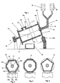
- FIG. 1 shows schematically a device for separating gold from solids.
- This device comprises a drum 10 having a shell 12 having an inner wall 12a and an outer wall 12b, with a lower flange 14 and an upper flange 16.
- the drum is about its axis of rotation DD arranged obliquely with respect to the horizontal, wherein the inclination angle ⁇ against the horizontal is preferably between 20 ° and 40 °, preferably about 30 °.
- the jacket 12 In the vicinity of the lower end, the jacket 12 has an opening 22, from which an access flange 23 extends, which can be closed by means of a cover 24.
- a drive shaft 42 to an electric motor 40.
- a drip tray 48 can be arranged, in the drum 10 at a suitable rotational position of the drum drum contents through the opening 22 can be emptied.
- the upper flange 16 has a bore 18 coaxial with the axis of rotation. In this bore extends the axial portion 32 of a tube 30.
- This axial portion 32 of the tube 30 is connected via a rotary seal 20 tightly connected to the upper flange 16, but decoupled in the direction of rotation, so that the tube 30 remains rigid upon rotation of the drum 10 ,
- There are two acid tanks 35, 36 are provided, the contents of which can be discharged via the pipe 30 into the interior of the drum.
- support rollers 44a to c are provided, on which the lateral surface 16a of the upper flange, which thus serves as a support surface, rests.
- the sheath 12 is not a hollow cylinder having a circular cross-section, but the inner wall (12a) and the outer wall (12b) have a polygonal cross-section, namely, the cross section of a regular hexagon.
- the drum is preferably made of a plastic, namely polypropylene in particular, it is in principle possible to produce the shell 12 of the drum 10 by injection molding. Due to the size and the relatively small number of units in which such systems are built, this is usually too expensive. Therefore, it is preferable to weld the sheath 12 of chamfered plastic plates. As a result, the hexagonal cross section of the outer wall comes about, which is irrelevant to the operation of the device.
- the operation of the device is basically known from the prior art: About the access flange 23 is in a position such as the FIG. 1 corresponds, the solid to be recycled, usually in the form of granules, introduced into the interior of the drum. Subsequently, the access flange 23 is closed with the lid 24. Hydrochloric acid and nitric acid in the correct mixing ratio are now added via the tube 30 and the drum 10 is rotated by means of the motor 40. Due to the polygonal cross section of the inner wall 12a of the shell, the friction between the granules and the inner wall of the shell as well as the "internal friction" of the granules is increased, whereby the reaction rate is accelerated in the solution of the gold. After the release operation is completed, the drum 10 is emptied through the access flange 23, wherein the drum opposite to the in FIG. 1 Shown rotated 180 degrees.
Landscapes
- Engineering & Computer Science (AREA)
- Chemical & Material Sciences (AREA)
- Manufacturing & Machinery (AREA)
- Materials Engineering (AREA)
- Mechanical Engineering (AREA)
- Metallurgy (AREA)
- Organic Chemistry (AREA)
- Life Sciences & Earth Sciences (AREA)
- Environmental & Geological Engineering (AREA)
- General Life Sciences & Earth Sciences (AREA)
- Geology (AREA)
- Manufacture And Refinement Of Metals (AREA)
Abstract
Description
- Die Erfindung betrifft eine Vorrichtung für das Edelmetall-Recycling, insbesondere für das Recycling von Gold, nach dem Oberbegriff des Anspruchs 1.
- Schon seit sehr langer Zeit ist es bekannt, dass man mit sogenanntem Königswasser (eine Mischung aus Salzsäure und Salpetersäure) metallisches Gold oxidieren und somit in eine wässrige Lösung überführen kann. Solches Königswasser wird auch noch heutzutage zur Abscheidung von Gold, beispielsweise aus technischen Abfällen oder von vergoldeten Gebrauchsgegenständen, verwendet.
- Gold löst sich (im Gegensatz zu Platin) auch in kaltem Königswasser (also im Wesentlichen bei Zimmertemperatur), jedoch nimmt die Reaktionsgeschwindigkeit mit steigender Temperatur zu, so dass auch zum Abscheiden von Gold häufig heißes Königswasser mit einer Temperatur von 60°C eingesetzt wird. Der Einsatz von heißem Königswasser ist jedoch mit Nachteilen behaftet, insbesondere da heißes Königswasser nur in Glasgefäßen gehandhabt werden kann und da relativ große Mengen aggressiver Dämpfe entstehen.
- Es wurden deshalb in der Vergangenheit Vorrichtungen entwickelt, welche auch beim Einsatz von kaltem Königswasser eine akzeptable Reaktionsgeschwindigkeit erzielen. Solche Vorrichtungen, wie sie der vorliegenden Erfindung als gattungsbildend zu Grunde liegen, sind wie folgt aufgebaut: Das zentrale Bauelement einer solchen Vorrichtung ist eine um eine Drehachse drehbar angeordnete Trommel, wobei die Drehachse schräg zur Horizontalen (beispielsweise in einem Winkel von 20 bis 30 Grad) verläuft. Diese Trommel weist einen hohlzylindrischen Mantel und zwei diesen Mantel an seinen Stirnseiten verschließende Flansche auf, wobei diese Flansche die Stirnwände der Trommel bilden. An dem unteren Flansch ist koaxial ein Elektromotor angeschlossen, mit dem sich die Trommel in Rotation versetzen lässt. Der obere Flansch weist eine zur Drehachse koaxiale Bohrung auf, durch die sich ein Rohr ins Innere der Trommel erstreckt. Dieses Rohr ist mittels einer Drehdichtung mit dem oberen Flansch verbunden. Mit diesem Rohr sind weiterhin zwei Säurebehälter verbunden, wobei einer dieser Säurebehälter für die Aufnahme von Salzsäure und der andere für die Aufnahme von Salpetersäure vorgesehen ist. Der Mantel der Trommel weist eine verschließbare Öffnung auf, über die das zu bearbeitende Material zugeführt werden kann und das entgoldete Material sowie die Lösung mit dem gelösten Gold entnommen werden können.
- Hiervon ausgehend stellt sich die vorliegende Erfindung die Aufgabe, eine solche Vorrichtung dahingehend weiterzubilden, dass mit ihr eine weiter erhöhte Reaktionsgeschwindigkeit erreicht werden kann, ohne dass eine Erwärmung der zugeführten Säuren notwendig ist.
- Diese Aufgabe wird durch eine Vorrichtung mit dem Merkmal des Anspruchs 1 gelöst.
- Es hat sich herausgestellt, dass die Reibung, welche bei den gattungsgemäßen Vorrichtungen für die Erhöhung der Reaktionsgeschwindigkeit mitverantwortlich zu sein scheint, schon allein dadurch signifikant erhöht werden kann, dass die Innenwand des Mantels der Trommel nicht mehr einen kreisförmigen, sondern einen vieleckigen Querschnitt aufweist. Dies scheint darin begründet zu liegen, dass die Bewegung des zumeist als Granulat vorliegenden zu entgoldenden Materials durch den vieleckigen Qurschnitts ungleichmäßiger ist, als es bei einem runden Querschnitt der Fall ist - die Granulatteilchen werden ständig beschleunigt und abgebremst. Hierbei haben sich insbesondere ein fünfeckiger, sechseckiger, siebeneckiger oder achteckiger Querschnitt, wobei die Vielecke vorzugsweise regelmäßige Vieleckige sind, als ideal herausgestellt. Der Herstellungs-Mehraufwand für eine erlindungsgemaße Vorrichtung ist gegenüber einer Vorrichtung gemäß dem Stand der Technik gering und die Handhabung der Vorrichtung unterscheidet sich von der Handhabung einer solchen Vorrichtung gemäß dem Stand der Technik nicht, mit Ausnahme des höheren Durchsatzes.
- In der Regel ist es notwendig, das obere Ende der Trommel abzustützen, da die Drehdichtung, welche das Rohr mit der oberen Stirnwand (Flansch) verbindet, in der Regel nicht zur Aufnahme von hohen Kräften ausgelegt ist. Daher ist es zu bevorzugen, dass, wie dies im Stand der Technik grundsätzlich bekannt ist, wenigstens eine Abstützrolle vorgesehen ist, welche das obere Ende der Trommel abstützt. Wenn jedoch die Innenwand des Mantels der Trommel einen vieleckigen Querschnitt haben soll, so ist es aus herstellungstechnischer Sicht zu bevorzugen, dass auch die Außenwand einen entsprechenden mehreckigen Querschnitt aufweist. Eine Außenwand mit einem vieleckigen Querschnitt ist jedoch nicht gut dafür geeignet, durch Abstützrollen abgestützt zu werden. Es ist deshalb zu bevorzugen, dass die Mantelfläche der Trommel eine nach außen weisende Abstützfläche mit kreisrundem Querschnitt aufweist. Hierfür wird bevorzugt der obere Flansch genutzt.
- Die Erfindung wird nun anhand von Ausführungsbeispielen mit Bezug auf die Figuren näher erläutert. Hierbei zeigen
- Figur 1
- einen schematisierten Längsschnitt durch eine erfindungsgemäße Vorrichtung,
- Figur 2
- einen Schnitt entlang der Ebene A-A aus
Figur 1 , - Figur 3
- eine Variante zu dem in
Figur 2 Gezeigten und - Figur 4
- eine weitere Variante zu dem in
Figur 2 Gezeigten. - Die
Figur 1 zeigt schematisch eine Vorrichtung zum Abscheiden von Gold aus Feststoffen. Diese Vorrichtung weist eine Trommel 10 mit einem eine Innenwand 12a und eine Außenwand 12b aufweisenden Mantel 12, mit einem unteren Flansch 14 und einem oberen Flansch 16 auf. Die Trommel ist um ihre Drehachse D-D schräg bezüglich der Horizontalen angeordnet, wobei der Neigungswinkel α gegen die Horizontale vorzugsweise zwischen 20° und 40°, vorzugsweise ca. 30° beträgt. Hierdurch ergibt sich eine Orientierung der Trommel 10 dahingehend, dass sie ein unteres Ende und ein oberes Ende aufweist. In der Nähe des unteren Endes weist der Mantel 12 eine Öffnung 22 auf, von der sich ein Zugangsflansch 23 erstreckt, welcher mittels eines Deckels 24 verschließbar ist. Vom unteren Flansch 14 erstreckt sich koaxial zur Drehachse D-D eine Antriebsachse 42 zu einem Elektromotor 40. Unterhalb der Trommel 10 ist eine Auffangwanne 48 anordenbar, in die bei geeigneter Drehposition der Trommel 10 der Trommelinhalt durch die Öffnung 22 entleerbar ist. Der obere Flansch 16 weist eine zur Drehachse koaxiale Bohrung 18 auf. In diese Bohrung erstreckt sich der axiale Abschnitt 32 eines Rohres 30. Dieser axiale Abschnitt 32 des Rohres 30 ist über eine Drehdichtung 20 dicht mit dem oberen Flansch 16 verbunden, in Drehrichtung jedoch entkoppelt, so dass das Rohr 30 bei Drehung der Trommel 10 starr bleibt. Es sind zwei Säurebehälter 35, 36 vorgesehen, deren Inhalt über das Rohr 30 in das Innere der Trommel abgelassen werden kann. Es sind entsprechende Absperrventile vorgesehen. Zur Abstützung des oberen Endes der Trommel 10 sind Abstützrollen 44a bis c vorgesehen, auf welchen die Mantelfläche 16a des oberen Flansches, welche somit als Abstützfläche dient, aufliegt. - Wie man der
Figur 2 unmittelbar entnimmt, ist der Mantel 12 kein Hohlzylinder mit kreisrundem Querschnitt, sondern die Innenwand (12a) und die Außenwand (12b) haben einen vieleckigen Querschnitt, nämlich den Querschnitt eines regelmäßigen Sechseckes. Da die Trommel vorzugsweise aus einem Kunststoff, nämlich insbesondere aus Polypropylen, besteht, ist es grundsätzlich möglich, den Mantel 12 der Trommel 10 im Spritzgussverfahren herzustellen. Auf Grund der Größe und der relativ geringen Stückzahl, in welcher solche Anlagen gebaut werden, ist dies in der Regel jedoch zu aufwendig. Deshalb ist es zu bevorzugen, den Mantel 12 aus abgeschrägten Kunststoffplatten zu schweißen. Hierdurch kommt auch der sechseckige Querschnitt der Außenwand zustande, welche für die Funktionsweise der Vorrichtung ohne Bedeutung ist. - Die Funktionsweise der Vorrichtung ist grundsätzlich aus dem Stand der Technik bekannt: Über den Zugangsflansch 23 wird in einer Stellung, wie sie der
Figur 1 entspricht, der zu recycelnde Feststoff, meist in Form eines Granulats, in das Innere der Trommel eingebracht. Anschließend wird der Zugangsflansch 23 mit dem Deckel 24 verschlossen. Es werden nun über das Rohr 30 Salzsäure und Salpetersäure im richtigen Mischungsverhältnis zugegeben und die Trommel 10 mittels des Motors 40 in Drehung versetzt. Durch den vieleckigen Querschnitt der Innenwand 12a des Mantels wird die Reibung zwischen Granulat und Innenwand des Mantels wie auch die "innere Reibung" des Granulats erhöht, wodurch die Reaktionsgeschwindigkeit bei der Lösung des Goldes beschleunigt wird. Nachdem der Lösevorgang abgeschlossen ist, wird die Trommel 10 über den Zugangsflansch 23 entleert, wobei die Trommel gegenüber dem inFigur 1 Gezeigten um 180 Grad gedreht ist. - Ein regelmäßiger sechseckiger Querschnitt der Innenwand 12a hat sich als sehr günstig herausgestellt, ebenfalls als günstig hat sich ein achteckiger und ein fünfeckiger Querschnitt (siehe
Figuren 3 und 4 ) herausgestellt. Bei Velecken mit noch mehr Ecken nimmt der erfindungsgemäße Effekt in der Regel ab, eine zu geringe Anzahl an Ecken ( Dreieck, Viereck) hat sich ebenfalls als nicht ideal erwiesen. - 10
- Trommel
- 12
- Mantel
- 12a
- Innenwand
- 12b
- Außenwand
- 14
- unterer Flansch
- 16
- oberer Flansch
- 16a
- Mantelfläche (Abstützfläche)
- 18
- Bohrung
- 20
- Drehdichtung
- 22
- Öffnung
- 23
- Zugangsflansch
- 24
- Deckel
- 30
- Rohr
- 32
- axialer Abschnitt
- 34
- vertikaler Abschnitt
- 35
- erster Säurebehälter (für Salzsäure)
- 36
- zweiter Säurebehälter (für Salpetersäure)
- 40
- Motor
- 42
- Antriebsachse
- 44a-c
- Abstützrolle
- 48
- Auffangwanne
Claims (8)
- Vorrichtung für das Edelmetall-Recycling mit
einer sich um eine schräg zur Horizontalen verlaufenden Drehachse (D-D) erstreckenden, drehbar gelagerten Trommel (10) mit einem Mantel (12) und zwei Stirnwänden, wobeider Mantel (12) wenigstens eine verschließbare Öffnung (22) aufweist und wobeidie obere Stirnwand eine Bohrung (18) aufweist, durch die ein Rohr (30) ins Innere der Trommel (10) mündet,einer Antriebseinrichtung, mittels der die Trommel (10) in Rotation versetzbar ist, und
wenigstens einem mit dem Rohr (30) in Fließverbindung stehenden Säurebehälter (35, 36),
dadurch gekennzeichnet, dass
zumindest die Innenwand (12a) des Mantels (12) einen vieleckigen Querschnitt hat. - Vorrichtung nach Anspruch 1, dadurch gekennzeichnet, dass das Vieleck ein Fünfeck, Sechseck, Siebeneck oder Achteck ist.
- Vorrichtung nach einem der vorangehenden Ansprüche, dadurch gekennzeichnet, dass das Vieleck ein regelmäßiges Vieleck ist.
- Vorrichtung nach einem der vorangehenden Ansprüche, dadurch gekennzeichnet, dass auch die Außenwand (12b) des Mantels ein Vieleck ist, so dass der Mantel aus mehreren miteinander verschweißten Platten besteht.
- Vorrichtung nach einem der vorangehenden Ansprüche, dadurch gekennzeichnet, dass die Trommel eine nach außen weisende Abstützfläche mit kreisrundem Querschnitt aufweist, welche sich konzentrisch zur Drehachse erstreckt, und dass wenigstens eine Abstützrolle (44a-c) vorgesehen ist, welche die Trommel über die Abstützfläche abstützt.
- Vorrichtung nach Anspruch 5, dadurch gekennzeichnet, dass die Abstützfläche die Mantelfläche (16a) eines Flansches (16) ist, welcher die obere Stirnwand bildet.
- Vorrichtung nach einem der vorangehenden Ansprüche, dadurch gekennzeichnet, dass die Antriebseinrichtung ein Motor (40) ist, welcher mittels einer Antriebsachse an die untere Stirnwand gekoppelt ist.
- Vorrichtung nach einem der vorangehenden Ansprüche, dadurch gekennzeichnet, dass zwei Säurebehälter mit dem Rohr in Fließverbindung stehen.
Priority Applications (2)
| Application Number | Priority Date | Filing Date | Title |
|---|---|---|---|
| PL12004215T PL2520676T3 (pl) | 2012-06-01 | 2012-06-01 | Urządzenie do recyklingu metali szlachetnych |
| EP20120004215 EP2520676B1 (de) | 2012-06-01 | 2012-06-01 | Vorrichtung für das Edelmetall-Recycling |
Applications Claiming Priority (1)
| Application Number | Priority Date | Filing Date | Title |
|---|---|---|---|
| EP20120004215 EP2520676B1 (de) | 2012-06-01 | 2012-06-01 | Vorrichtung für das Edelmetall-Recycling |
Publications (2)
| Publication Number | Publication Date |
|---|---|
| EP2520676A1 true EP2520676A1 (de) | 2012-11-07 |
| EP2520676B1 EP2520676B1 (de) | 2014-07-23 |
Family
ID=46319508
Family Applications (1)
| Application Number | Title | Priority Date | Filing Date |
|---|---|---|---|
| EP20120004215 Active EP2520676B1 (de) | 2012-06-01 | 2012-06-01 | Vorrichtung für das Edelmetall-Recycling |
Country Status (2)
| Country | Link |
|---|---|
| EP (1) | EP2520676B1 (de) |
| PL (1) | PL2520676T3 (de) |
Citations (2)
| Publication number | Priority date | Publication date | Assignee | Title |
|---|---|---|---|---|
| US4426251A (en) * | 1982-09-29 | 1984-01-17 | Storage Technology Corporation | Portable gold recovery apparatus and method for using same |
| US6613271B1 (en) * | 1998-03-13 | 2003-09-02 | Alexander Hamilton Lewis-Gray | Apparatus and methods for recovering valuable metals |
-
2012
- 2012-06-01 PL PL12004215T patent/PL2520676T3/pl unknown
- 2012-06-01 EP EP20120004215 patent/EP2520676B1/de active Active
Patent Citations (2)
| Publication number | Priority date | Publication date | Assignee | Title |
|---|---|---|---|---|
| US4426251A (en) * | 1982-09-29 | 1984-01-17 | Storage Technology Corporation | Portable gold recovery apparatus and method for using same |
| US6613271B1 (en) * | 1998-03-13 | 2003-09-02 | Alexander Hamilton Lewis-Gray | Apparatus and methods for recovering valuable metals |
Also Published As
| Publication number | Publication date |
|---|---|
| PL2520676T3 (pl) | 2015-02-27 |
| EP2520676B1 (de) | 2014-07-23 |
Similar Documents
| Publication | Publication Date | Title |
|---|---|---|
| EP1859856B1 (de) | Mischvorrichtung mit Vakuum-Box | |
| EP2373550B1 (de) | Verschluss für einen behälter | |
| DE3212700C2 (de) | ||
| AT507834A1 (de) | Portionskapsel | |
| EP1813376A1 (de) | Befestigungselement zur Reibschweißverbindung mit einem flächigen Bauteil | |
| EP0103900A1 (de) | Fliessbettapparatur | |
| DE2826611A1 (de) | Vorrichtung zum ueberziehen der innenflaeche von rohrkoerpern | |
| DE69406759T2 (de) | Verbesserungen betreffend drehöfen | |
| WO2014161819A1 (de) | Vorrichtung und verfahren zum abscheiden von magnetisierbaren partikeln aus einem fluid | |
| DE2048226A1 (de) | Drehofen | |
| DE102010062223A1 (de) | Leicht zu öffnender Ventilverschluss | |
| DE19615646A1 (de) | Kupplungseinrichtung zum Verbinden bzw. Verschließen der innerhalb zweier eigenständiger Gehäuse befindlichen Räume | |
| EP3117840B1 (de) | Behandlungs- und transportbehälter mit einem klappenventil sowie verfahren zum entleeren eines solchen | |
| DE102013101645A1 (de) | Transporteur für Flaschen oder dergleichen Behälter sowie Behälterbehandlungsmaschine | |
| EP2520676B1 (de) | Vorrichtung für das Edelmetall-Recycling | |
| DE2544716A1 (de) | Saugfoerderanlage | |
| DE2657031C3 (de) | Ausgleichsplatte für eine Druck* filtrationszelle | |
| EP3137396B1 (de) | Verschlussanordnung, verfahren zum verschliessen eines verschlusses und schüttgutbehälter damit | |
| EP0194501A2 (de) | Entnahmekopf für Flüssigkeitsbehälter | |
| EP4194174B1 (de) | Vorrichtung zum ablösen zusammenfaltbarer innenbeutel von den innenwänden starrer aussenbehälter | |
| CH623486A5 (de) | ||
| DE2207207C3 (de) | ||
| EP1317988A2 (de) | Bauteil bei Fahrwerkskomponenten mit einer durch Pressschweissen erzeugten Verbindung | |
| WO2023094043A1 (de) | Verfahren und vorrichtung zum falten | |
| DE2649248A1 (de) | Vorrichtung zur beschickung eines schachtofens, insbesondere eines hochofens |
Legal Events
| Date | Code | Title | Description |
|---|---|---|---|
| PUAI | Public reference made under article 153(3) epc to a published international application that has entered the european phase |
Free format text: ORIGINAL CODE: 0009012 |
|
| AK | Designated contracting states |
Kind code of ref document: A1 Designated state(s): AL AT BE BG CH CY CZ DE DK EE ES FI FR GB GR HR HU IE IS IT LI LT LU LV MC MK MT NL NO PL PT RO RS SE SI SK SM TR |
|
| AX | Request for extension of the european patent |
Extension state: BA ME |
|
| 17P | Request for examination filed |
Effective date: 20121006 |
|
| GRAJ | Information related to disapproval of communication of intention to grant by the applicant or resumption of examination proceedings by the epo deleted |
Free format text: ORIGINAL CODE: EPIDOSDIGR1 |
|
| GRAP | Despatch of communication of intention to grant a patent |
Free format text: ORIGINAL CODE: EPIDOSNIGR1 |
|
| RIC1 | Information provided on ipc code assigned before grant |
Ipc: C22B 7/00 20060101ALI20140303BHEP Ipc: C22B 11/00 20060101AFI20140303BHEP |
|
| GRAP | Despatch of communication of intention to grant a patent |
Free format text: ORIGINAL CODE: EPIDOSNIGR1 |
|
| INTG | Intention to grant announced |
Effective date: 20140423 |
|
| GRAS | Grant fee paid |
Free format text: ORIGINAL CODE: EPIDOSNIGR3 |
|
| GRAA | (expected) grant |
Free format text: ORIGINAL CODE: 0009210 |
|
| AK | Designated contracting states |
Kind code of ref document: B1 Designated state(s): AL AT BE BG CH CY CZ DE DK EE ES FI FR GB GR HR HU IE IS IT LI LT LU LV MC MK MT NL NO PL PT RO RS SE SI SK SM TR |
|
| REG | Reference to a national code |
Ref country code: GB Ref legal event code: FG4D Free format text: NOT ENGLISH |
|
| REG | Reference to a national code |
Ref country code: CH Ref legal event code: EP |
|
| REG | Reference to a national code |
Ref country code: IE Ref legal event code: FG4D Free format text: LANGUAGE OF EP DOCUMENT: GERMAN |
|
| REG | Reference to a national code |
Ref country code: AT Ref legal event code: REF Ref document number: 678939 Country of ref document: AT Kind code of ref document: T Effective date: 20140815 |
|
| REG | Reference to a national code |
Ref country code: DE Ref legal event code: R096 Ref document number: 502012001026 Country of ref document: DE Effective date: 20140904 |
|
| REG | Reference to a national code |
Ref country code: DE Ref legal event code: R082 Ref document number: 502012001026 Country of ref document: DE Representative=s name: FRANK WACKER SCHOEN PATENTANWAELTE, DE Ref country code: DE Ref legal event code: R082 Ref document number: 502012001026 Country of ref document: DE Representative=s name: SCHOEN, THILO, DIPL.-PHYS., DE |
|
| RAP2 | Party data changed (patent owner data changed or rights of a patent transferred) |
Owner name: KORAS, THORSTEN |
|
| RIN2 | Information on inventor provided after grant (corrected) |
Inventor name: KORAS, THORSTEN |
|
| REG | Reference to a national code |
Ref country code: NL Ref legal event code: VDEP Effective date: 20140723 |
|
| REG | Reference to a national code |
Ref country code: LT Ref legal event code: MG4D |
|
| PG25 | Lapsed in a contracting state [announced via postgrant information from national office to epo] |
Ref country code: GR Free format text: LAPSE BECAUSE OF FAILURE TO SUBMIT A TRANSLATION OF THE DESCRIPTION OR TO PAY THE FEE WITHIN THE PRESCRIBED TIME-LIMIT Effective date: 20141024 Ref country code: NO Free format text: LAPSE BECAUSE OF FAILURE TO SUBMIT A TRANSLATION OF THE DESCRIPTION OR TO PAY THE FEE WITHIN THE PRESCRIBED TIME-LIMIT Effective date: 20141023 Ref country code: FI Free format text: LAPSE BECAUSE OF FAILURE TO SUBMIT A TRANSLATION OF THE DESCRIPTION OR TO PAY THE FEE WITHIN THE PRESCRIBED TIME-LIMIT Effective date: 20140723 Ref country code: SE Free format text: LAPSE BECAUSE OF FAILURE TO SUBMIT A TRANSLATION OF THE DESCRIPTION OR TO PAY THE FEE WITHIN THE PRESCRIBED TIME-LIMIT Effective date: 20140723 Ref country code: PT Free format text: LAPSE BECAUSE OF FAILURE TO SUBMIT A TRANSLATION OF THE DESCRIPTION OR TO PAY THE FEE WITHIN THE PRESCRIBED TIME-LIMIT Effective date: 20141124 Ref country code: BG Free format text: LAPSE BECAUSE OF FAILURE TO SUBMIT A TRANSLATION OF THE DESCRIPTION OR TO PAY THE FEE WITHIN THE PRESCRIBED TIME-LIMIT Effective date: 20141023 Ref country code: LT Free format text: LAPSE BECAUSE OF FAILURE TO SUBMIT A TRANSLATION OF THE DESCRIPTION OR TO PAY THE FEE WITHIN THE PRESCRIBED TIME-LIMIT Effective date: 20140723 Ref country code: ES Free format text: LAPSE BECAUSE OF FAILURE TO SUBMIT A TRANSLATION OF THE DESCRIPTION OR TO PAY THE FEE WITHIN THE PRESCRIBED TIME-LIMIT Effective date: 20140723 |
|
| PG25 | Lapsed in a contracting state [announced via postgrant information from national office to epo] |
Ref country code: IS Free format text: LAPSE BECAUSE OF FAILURE TO SUBMIT A TRANSLATION OF THE DESCRIPTION OR TO PAY THE FEE WITHIN THE PRESCRIBED TIME-LIMIT Effective date: 20141123 Ref country code: CY Free format text: LAPSE BECAUSE OF FAILURE TO SUBMIT A TRANSLATION OF THE DESCRIPTION OR TO PAY THE FEE WITHIN THE PRESCRIBED TIME-LIMIT Effective date: 20140723 Ref country code: NL Free format text: LAPSE BECAUSE OF FAILURE TO SUBMIT A TRANSLATION OF THE DESCRIPTION OR TO PAY THE FEE WITHIN THE PRESCRIBED TIME-LIMIT Effective date: 20140723 Ref country code: LV Free format text: LAPSE BECAUSE OF FAILURE TO SUBMIT A TRANSLATION OF THE DESCRIPTION OR TO PAY THE FEE WITHIN THE PRESCRIBED TIME-LIMIT Effective date: 20140723 Ref country code: HR Free format text: LAPSE BECAUSE OF FAILURE TO SUBMIT A TRANSLATION OF THE DESCRIPTION OR TO PAY THE FEE WITHIN THE PRESCRIBED TIME-LIMIT Effective date: 20140723 Ref country code: RS Free format text: LAPSE BECAUSE OF FAILURE TO SUBMIT A TRANSLATION OF THE DESCRIPTION OR TO PAY THE FEE WITHIN THE PRESCRIBED TIME-LIMIT Effective date: 20140723 |
|
| REG | Reference to a national code |
Ref country code: PL Ref legal event code: T3 |
|
| REG | Reference to a national code |
Ref country code: DE Ref legal event code: R097 Ref document number: 502012001026 Country of ref document: DE |
|
| PG25 | Lapsed in a contracting state [announced via postgrant information from national office to epo] |
Ref country code: RO Free format text: LAPSE BECAUSE OF FAILURE TO SUBMIT A TRANSLATION OF THE DESCRIPTION OR TO PAY THE FEE WITHIN THE PRESCRIBED TIME-LIMIT Effective date: 20140723 Ref country code: SK Free format text: LAPSE BECAUSE OF FAILURE TO SUBMIT A TRANSLATION OF THE DESCRIPTION OR TO PAY THE FEE WITHIN THE PRESCRIBED TIME-LIMIT Effective date: 20140723 Ref country code: CZ Free format text: LAPSE BECAUSE OF FAILURE TO SUBMIT A TRANSLATION OF THE DESCRIPTION OR TO PAY THE FEE WITHIN THE PRESCRIBED TIME-LIMIT Effective date: 20140723 Ref country code: EE Free format text: LAPSE BECAUSE OF FAILURE TO SUBMIT A TRANSLATION OF THE DESCRIPTION OR TO PAY THE FEE WITHIN THE PRESCRIBED TIME-LIMIT Effective date: 20140723 Ref country code: DK Free format text: LAPSE BECAUSE OF FAILURE TO SUBMIT A TRANSLATION OF THE DESCRIPTION OR TO PAY THE FEE WITHIN THE PRESCRIBED TIME-LIMIT Effective date: 20140723 |
|
| PLBE | No opposition filed within time limit |
Free format text: ORIGINAL CODE: 0009261 |
|
| STAA | Information on the status of an ep patent application or granted ep patent |
Free format text: STATUS: NO OPPOSITION FILED WITHIN TIME LIMIT |
|
| 26N | No opposition filed |
Effective date: 20150424 |
|
| PG25 | Lapsed in a contracting state [announced via postgrant information from national office to epo] |
Ref country code: SI Free format text: LAPSE BECAUSE OF FAILURE TO SUBMIT A TRANSLATION OF THE DESCRIPTION OR TO PAY THE FEE WITHIN THE PRESCRIBED TIME-LIMIT Effective date: 20140723 |
|
| PG25 | Lapsed in a contracting state [announced via postgrant information from national office to epo] |
Ref country code: MC Free format text: LAPSE BECAUSE OF FAILURE TO SUBMIT A TRANSLATION OF THE DESCRIPTION OR TO PAY THE FEE WITHIN THE PRESCRIBED TIME-LIMIT Effective date: 20140723 |
|
| PG25 | Lapsed in a contracting state [announced via postgrant information from national office to epo] |
Ref country code: LU Free format text: LAPSE BECAUSE OF FAILURE TO SUBMIT A TRANSLATION OF THE DESCRIPTION OR TO PAY THE FEE WITHIN THE PRESCRIBED TIME-LIMIT Effective date: 20150601 |
|
| REG | Reference to a national code |
Ref country code: IE Ref legal event code: MM4A |
|
| REG | Reference to a national code |
Ref country code: FR Ref legal event code: ST Effective date: 20160229 |
|
| PG25 | Lapsed in a contracting state [announced via postgrant information from national office to epo] |
Ref country code: IE Free format text: LAPSE BECAUSE OF NON-PAYMENT OF DUE FEES Effective date: 20150601 |
|
| PG25 | Lapsed in a contracting state [announced via postgrant information from national office to epo] |
Ref country code: FR Free format text: LAPSE BECAUSE OF NON-PAYMENT OF DUE FEES Effective date: 20150630 |
|
| PG25 | Lapsed in a contracting state [announced via postgrant information from national office to epo] |
Ref country code: MT Free format text: LAPSE BECAUSE OF FAILURE TO SUBMIT A TRANSLATION OF THE DESCRIPTION OR TO PAY THE FEE WITHIN THE PRESCRIBED TIME-LIMIT Effective date: 20140723 |
|
| GBPC | Gb: european patent ceased through non-payment of renewal fee |
Effective date: 20160601 |
|
| PG25 | Lapsed in a contracting state [announced via postgrant information from national office to epo] |
Ref country code: HU Free format text: LAPSE BECAUSE OF FAILURE TO SUBMIT A TRANSLATION OF THE DESCRIPTION OR TO PAY THE FEE WITHIN THE PRESCRIBED TIME-LIMIT; INVALID AB INITIO Effective date: 20120601 Ref country code: SM Free format text: LAPSE BECAUSE OF FAILURE TO SUBMIT A TRANSLATION OF THE DESCRIPTION OR TO PAY THE FEE WITHIN THE PRESCRIBED TIME-LIMIT Effective date: 20140723 Ref country code: GB Free format text: LAPSE BECAUSE OF NON-PAYMENT OF DUE FEES Effective date: 20160601 |
|
| PG25 | Lapsed in a contracting state [announced via postgrant information from national office to epo] |
Ref country code: BE Free format text: LAPSE BECAUSE OF NON-PAYMENT OF DUE FEES Effective date: 20150630 |
|
| REG | Reference to a national code |
Ref country code: DE Ref legal event code: R082 Ref document number: 502012001026 Country of ref document: DE Representative=s name: SCHOEN, THILO, DIPL.-PHYS., DE |
|
| PG25 | Lapsed in a contracting state [announced via postgrant information from national office to epo] |
Ref country code: MK Free format text: LAPSE BECAUSE OF FAILURE TO SUBMIT A TRANSLATION OF THE DESCRIPTION OR TO PAY THE FEE WITHIN THE PRESCRIBED TIME-LIMIT Effective date: 20140723 |
|
| PG25 | Lapsed in a contracting state [announced via postgrant information from national office to epo] |
Ref country code: AL Free format text: LAPSE BECAUSE OF FAILURE TO SUBMIT A TRANSLATION OF THE DESCRIPTION OR TO PAY THE FEE WITHIN THE PRESCRIBED TIME-LIMIT Effective date: 20140723 |
|
| P01 | Opt-out of the competence of the unified patent court (upc) registered |
Effective date: 20230523 |
|
| PGFP | Annual fee paid to national office [announced via postgrant information from national office to epo] |
Ref country code: DE Payment date: 20250826 Year of fee payment: 14 |
|
| PGFP | Annual fee paid to national office [announced via postgrant information from national office to epo] |
Ref country code: IT Payment date: 20250630 Year of fee payment: 14 |
|
| PGFP | Annual fee paid to national office [announced via postgrant information from national office to epo] |
Ref country code: CH Payment date: 20250701 Year of fee payment: 14 |
|
| REG | Reference to a national code |
Ref country code: CH Ref legal event code: U11 Free format text: ST27 STATUS EVENT CODE: U-0-0-U10-U11 (AS PROVIDED BY THE NATIONAL OFFICE) Effective date: 20260701 |
|
| PGFP | Annual fee paid to national office [announced via postgrant information from national office to epo] |
Ref country code: PL Payment date: 20260519 Year of fee payment: 15 |
|
| PGFP | Annual fee paid to national office [announced via postgrant information from national office to epo] |
Ref country code: AT Payment date: 20260618 Year of fee payment: 15 |
|
| PGFP | Annual fee paid to national office [announced via postgrant information from national office to epo] |
Ref country code: TR Payment date: 20260525 Year of fee payment: 15 |