EP2520876B1 - Kit pour monter un toit photovoltaïque - Google Patents
Kit pour monter un toit photovoltaïque Download PDFInfo
- Publication number
- EP2520876B1 EP2520876B1 EP11425124A EP11425124A EP2520876B1 EP 2520876 B1 EP2520876 B1 EP 2520876B1 EP 11425124 A EP11425124 A EP 11425124A EP 11425124 A EP11425124 A EP 11425124A EP 2520876 B1 EP2520876 B1 EP 2520876B1
- Authority
- EP
- European Patent Office
- Prior art keywords
- solar panel
- disposed
- kit
- tailpiece
- support bar
- Prior art date
- Legal status (The legal status is an assumption and is not a legal conclusion. Google has not performed a legal analysis and makes no representation as to the accuracy of the status listed.)
- Not-in-force
Links
- 238000000576 coating method Methods 0.000 claims abstract description 28
- 239000011248 coating agent Substances 0.000 claims abstract description 27
- 125000006850 spacer group Chemical group 0.000 claims abstract description 17
- XLYOFNOQVPJJNP-UHFFFAOYSA-N water Substances O XLYOFNOQVPJJNP-UHFFFAOYSA-N 0.000 claims description 11
- 238000011144 upstream manufacturing Methods 0.000 claims description 9
- 230000008878 coupling Effects 0.000 claims description 8
- 238000010168 coupling process Methods 0.000 claims description 8
- 238000005859 coupling reaction Methods 0.000 claims description 8
- 238000010276 construction Methods 0.000 claims description 6
- 230000000284 resting effect Effects 0.000 claims description 5
- 238000007789 sealing Methods 0.000 claims description 5
- 238000003491 array Methods 0.000 claims description 2
- 229920002457 flexible plastic Polymers 0.000 claims description 2
- 239000000463 material Substances 0.000 claims description 2
- 238000009434 installation Methods 0.000 description 7
- 229910052751 metal Inorganic materials 0.000 description 4
- 239000002184 metal Substances 0.000 description 4
- 239000004411 aluminium Substances 0.000 description 2
- 229910052782 aluminium Inorganic materials 0.000 description 2
- XAGFODPZIPBFFR-UHFFFAOYSA-N aluminium Chemical compound [Al] XAGFODPZIPBFFR-UHFFFAOYSA-N 0.000 description 2
- 230000004888 barrier function Effects 0.000 description 2
- 238000000034 method Methods 0.000 description 2
- 229910021417 amorphous silicon Inorganic materials 0.000 description 1
- 239000003795 chemical substances by application Substances 0.000 description 1
- 239000005340 laminated glass Substances 0.000 description 1
- 238000004519 manufacturing process Methods 0.000 description 1
- 229910021421 monocrystalline silicon Inorganic materials 0.000 description 1
- 239000004033 plastic Substances 0.000 description 1
- 229920003023 plastic Polymers 0.000 description 1
- 239000004417 polycarbonate Substances 0.000 description 1
- 229920000515 polycarbonate Polymers 0.000 description 1
- 229910021420 polycrystalline silicon Inorganic materials 0.000 description 1
- 239000010409 thin film Substances 0.000 description 1
Images


Classifications
-
- H—ELECTRICITY
- H02—GENERATION; CONVERSION OR DISTRIBUTION OF ELECTRIC POWER
- H02S—GENERATION OF ELECTRIC POWER BY CONVERSION OF INFRARED RADIATION, VISIBLE LIGHT OR ULTRAVIOLET LIGHT, e.g. USING PHOTOVOLTAIC [PV] MODULES
- H02S20/00—Supporting structures for PV modules
- H02S20/20—Supporting structures directly fixed to an immovable object
- H02S20/22—Supporting structures directly fixed to an immovable object specially adapted for buildings
- H02S20/23—Supporting structures directly fixed to an immovable object specially adapted for buildings specially adapted for roof structures
-
- F—MECHANICAL ENGINEERING; LIGHTING; HEATING; WEAPONS; BLASTING
- F24—HEATING; RANGES; VENTILATING
- F24S—SOLAR HEAT COLLECTORS; SOLAR HEAT SYSTEMS
- F24S20/00—Solar heat collectors specially adapted for particular uses or environments
- F24S20/60—Solar heat collectors integrated in fixed constructions, e.g. in buildings
- F24S20/67—Solar heat collectors integrated in fixed constructions, e.g. in buildings in the form of roof constructions
-
- F—MECHANICAL ENGINEERING; LIGHTING; HEATING; WEAPONS; BLASTING
- F24—HEATING; RANGES; VENTILATING
- F24S—SOLAR HEAT COLLECTORS; SOLAR HEAT SYSTEMS
- F24S25/00—Arrangement of stationary mountings or supports for solar heat collector modules
- F24S25/20—Peripheral frames for modules
-
- F—MECHANICAL ENGINEERING; LIGHTING; HEATING; WEAPONS; BLASTING
- F24—HEATING; RANGES; VENTILATING
- F24S—SOLAR HEAT COLLECTORS; SOLAR HEAT SYSTEMS
- F24S25/00—Arrangement of stationary mountings or supports for solar heat collector modules
- F24S25/30—Arrangement of stationary mountings or supports for solar heat collector modules using elongate rigid mounting elements extending substantially along the supporting surface, e.g. for covering buildings with solar heat collectors
- F24S25/33—Arrangement of stationary mountings or supports for solar heat collector modules using elongate rigid mounting elements extending substantially along the supporting surface, e.g. for covering buildings with solar heat collectors forming substantially planar assemblies, e.g. of coplanar or stacked profiles
- F24S25/35—Arrangement of stationary mountings or supports for solar heat collector modules using elongate rigid mounting elements extending substantially along the supporting surface, e.g. for covering buildings with solar heat collectors forming substantially planar assemblies, e.g. of coplanar or stacked profiles by means of profiles with a cross-section defining separate supporting portions for adjacent modules
-
- F—MECHANICAL ENGINEERING; LIGHTING; HEATING; WEAPONS; BLASTING
- F24—HEATING; RANGES; VENTILATING
- F24S—SOLAR HEAT COLLECTORS; SOLAR HEAT SYSTEMS
- F24S25/00—Arrangement of stationary mountings or supports for solar heat collector modules
- F24S25/60—Fixation means, e.g. fasteners, specially adapted for supporting solar heat collector modules
- F24S25/61—Fixation means, e.g. fasteners, specially adapted for supporting solar heat collector modules for fixing to the ground or to building structures
- F24S25/615—Fixation means, e.g. fasteners, specially adapted for supporting solar heat collector modules for fixing to the ground or to building structures for fixing to protruding parts of buildings, e.g. to corrugations or to standing seams
-
- F—MECHANICAL ENGINEERING; LIGHTING; HEATING; WEAPONS; BLASTING
- F24—HEATING; RANGES; VENTILATING
- F24S—SOLAR HEAT COLLECTORS; SOLAR HEAT SYSTEMS
- F24S25/00—Arrangement of stationary mountings or supports for solar heat collector modules
- F24S25/60—Fixation means, e.g. fasteners, specially adapted for supporting solar heat collector modules
- F24S25/65—Fixation means, e.g. fasteners, specially adapted for supporting solar heat collector modules for coupling adjacent supporting elements, e.g. for connecting profiles together
-
- F—MECHANICAL ENGINEERING; LIGHTING; HEATING; WEAPONS; BLASTING
- F24—HEATING; RANGES; VENTILATING
- F24S—SOLAR HEAT COLLECTORS; SOLAR HEAT SYSTEMS
- F24S40/00—Safety or protection arrangements of solar heat collectors; Preventing malfunction of solar heat collectors
- F24S40/40—Preventing corrosion; Protecting against dirt or contamination
- F24S40/44—Draining rainwater or condensation
-
- F—MECHANICAL ENGINEERING; LIGHTING; HEATING; WEAPONS; BLASTING
- F24—HEATING; RANGES; VENTILATING
- F24S—SOLAR HEAT COLLECTORS; SOLAR HEAT SYSTEMS
- F24S25/00—Arrangement of stationary mountings or supports for solar heat collector modules
- F24S25/60—Fixation means, e.g. fasteners, specially adapted for supporting solar heat collector modules
- F24S2025/6003—Fixation means, e.g. fasteners, specially adapted for supporting solar heat collector modules by clamping
-
- Y—GENERAL TAGGING OF NEW TECHNOLOGICAL DEVELOPMENTS; GENERAL TAGGING OF CROSS-SECTIONAL TECHNOLOGIES SPANNING OVER SEVERAL SECTIONS OF THE IPC; TECHNICAL SUBJECTS COVERED BY FORMER USPC CROSS-REFERENCE ART COLLECTIONS [XRACs] AND DIGESTS
- Y02—TECHNOLOGIES OR APPLICATIONS FOR MITIGATION OR ADAPTATION AGAINST CLIMATE CHANGE
- Y02B—CLIMATE CHANGE MITIGATION TECHNOLOGIES RELATED TO BUILDINGS, e.g. HOUSING, HOUSE APPLIANCES OR RELATED END-USER APPLICATIONS
- Y02B10/00—Integration of renewable energy sources in buildings
- Y02B10/10—Photovoltaic [PV]
-
- Y—GENERAL TAGGING OF NEW TECHNOLOGICAL DEVELOPMENTS; GENERAL TAGGING OF CROSS-SECTIONAL TECHNOLOGIES SPANNING OVER SEVERAL SECTIONS OF THE IPC; TECHNICAL SUBJECTS COVERED BY FORMER USPC CROSS-REFERENCE ART COLLECTIONS [XRACs] AND DIGESTS
- Y02—TECHNOLOGIES OR APPLICATIONS FOR MITIGATION OR ADAPTATION AGAINST CLIMATE CHANGE
- Y02B—CLIMATE CHANGE MITIGATION TECHNOLOGIES RELATED TO BUILDINGS, e.g. HOUSING, HOUSE APPLIANCES OR RELATED END-USER APPLICATIONS
- Y02B10/00—Integration of renewable energy sources in buildings
- Y02B10/20—Solar thermal
-
- Y—GENERAL TAGGING OF NEW TECHNOLOGICAL DEVELOPMENTS; GENERAL TAGGING OF CROSS-SECTIONAL TECHNOLOGIES SPANNING OVER SEVERAL SECTIONS OF THE IPC; TECHNICAL SUBJECTS COVERED BY FORMER USPC CROSS-REFERENCE ART COLLECTIONS [XRACs] AND DIGESTS
- Y02—TECHNOLOGIES OR APPLICATIONS FOR MITIGATION OR ADAPTATION AGAINST CLIMATE CHANGE
- Y02E—REDUCTION OF GREENHOUSE GAS [GHG] EMISSIONS, RELATED TO ENERGY GENERATION, TRANSMISSION OR DISTRIBUTION
- Y02E10/00—Energy generation through renewable energy sources
- Y02E10/40—Solar thermal energy, e.g. solar towers
- Y02E10/47—Mountings or tracking
-
- Y—GENERAL TAGGING OF NEW TECHNOLOGICAL DEVELOPMENTS; GENERAL TAGGING OF CROSS-SECTIONAL TECHNOLOGIES SPANNING OVER SEVERAL SECTIONS OF THE IPC; TECHNICAL SUBJECTS COVERED BY FORMER USPC CROSS-REFERENCE ART COLLECTIONS [XRACs] AND DIGESTS
- Y02—TECHNOLOGIES OR APPLICATIONS FOR MITIGATION OR ADAPTATION AGAINST CLIMATE CHANGE
- Y02E—REDUCTION OF GREENHOUSE GAS [GHG] EMISSIONS, RELATED TO ENERGY GENERATION, TRANSMISSION OR DISTRIBUTION
- Y02E10/00—Energy generation through renewable energy sources
- Y02E10/50—Photovoltaic [PV] energy
Definitions
- the present invention relates to a kit for installing a photovoltaic roofing.
- the invention advantageously apply to manufacture and installation of solar photovoltaic systems in full replacement of, or to be integrated with the traditional coating surfaces.
- the invention relates to the installation of the so-called “solar roofs”, i.e. the installation of solar panels fully or partly constituting the covering or coating surface.
- solar roof it is intended a roof in which the traditional covering surface made of tiles or fretted plate, is fully or partly replaced with solar panels.
- the solar panels used consist of a plastic support to which the photovoltaic cells are fastened by a laminated glass sheet, the whole being framed by an aluminium support.
- the solar panels thus disposed are maintained in place by use of metal jaws acting on said guides, in turn fastened by screws to the bearing structure of the roof, by securing the solar panels along the sides of the support frames.
- these locking section members act along sides parallel to a descending direction of the roof pitch and are exclusively used for fastening the modules to the covering without contemplating impermeability of the system.
- the technical task underlying the present invention is to propose a kit for installing solar panels on a roof capable of overcoming the above mentioned drawbacks of the known art.
- a kit for installation of a photovoltaic roofing in accordance with the invention has been generally denoted at 1.
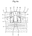
- Kit 1 comprises at least one photovoltaic solar panel 2 comprising one or more modules 3 and provided with a support frame 4 peripherally disposed around modules 3 for supporting and stiffening the solar panel 2 itself ( Fig. 8a ).
- modules 3 can be, just by way of example, of the crystalline type (single-crystal silicon, polycrystalline silicon, etc.) or of the thin-film type (consisting of amorphous silicon, etc.) or still others. They have a substantially rectangular shape.
- kit 1 comprises a plurality of solar panels 2 identical with each other.
- the solar panels 2 are arranged in one or more successions or arrays disposed along a sloping direction of a roof pitch and in side by side relationship with each other.
- Each solar panel 2 further comprises electric connection terminals (not shown in the figures) required for series connection of the solar panels 2 themselves.
- Kit 1 further comprises at least two support bars 5 extending along a major extension axis.
- Each support bar 5 comprises at least one fastening portion 5a designed to be fastened to a respective beam "T" of a bearing structure of a roof.
- the support bars 5 can be fastened to the sloping beams "T" of the roof defining the inclination of each roof pitch.
- each fastening portion 5a can be fastened to the respective beam “T" of the roof by screws or any other means necessary for ensuring steady fastening between the support bar 5 and the beam "T".
- Each support bar 5 further comprises two rest portions 5b preferably of one piece construction with the fastening portion 5a and placed along opposite sides of the fastening portion 5a.
- a respective spacer element is disposed on each rest portion 5b. At least one of the mentioned spacer elements is defined by one of the sides of the support frame 4 of the solar panel 2. In other configurations, both spacer elements are defined by respective sides of the support frames 4 of distinct solar panels 2.
- kit 1 comprises a plurality of support bars 5 identical with each other.
- the support bars 5 are fastened, parallel to each other, to respective beams "T" of the roof.
- Resting on each support bar 5 are the support frames 4 of distinct solar panels 2 disposed in side by side relationship.
- each solar panel 2 will be arranged on, and supported by, the rest portions 5b of two distinct support bars 5 ( Fig. 4a ).
- each support bar 5 carries a solar panel 2 resting on one of the rest portions 5b and one of the spacer elements on the other rest portion 5b ( Fig. 4b ).
- the spacer element may comprise a lath 6 to which a different coating element of the roof can be connected such as, by way of example, an array of bent tiles "C” or a fretted plate “D" ( Fig. 8 ).
- the support bars 5 all have the same length included between 200 cm and 700 cm, preferably between 300 cm and 600 cm.
- the support bars 5 will be cut. In the opposite case, two or more support bars 5 will be aligned until the pitch length is reached.
- the support bars 5 are made of metal.
- the support bars 5 are made of aluminium.
- each support bar 5 has a hollow section in a direction transverse to the major extension direction, so as to define a drain 7.
- each support bar 5 comprises a bottom wall 8 that can be coupled with the respective beam "T" and two side walls 9 transversely emerging, preferably in an orthogonal direction, from the bottom wall 8. The side walls 9 are therefore parallel to each other.
- the bottom wall 8 defines the fastening portion 5a of the support bar 5.
- the bottom wall 8 has two coplanar side portions that, in the fitting-out configuration, are in direct contact with the beam "T", and a middle portion placed between the side portions and parallel to the side portions but spaced apart therefrom.
- the fastening portion 5a is defined by the middle portion of the bottom wall 8.
- Each side wall 9 has a free edge 9a opposite to the bottom wall 8 and bent towards the other side wall 9.
- the bent free edges 9a are coplanar to each other for defining a rest surface. Therefore, the bent free edges 9a of the side walls 9 define the rest portions 5b of the support bars 5.
- Drain 7 is therefore defined by the bottom wall 8 in cooperation with the side walls 9.
- drain 7 is defined between each side portion of the bottom wall 8 and the respective side walls 9 disposed in side by side relationship.
- Kit 1 further comprises a plurality of locking bodies 10 each of which can be connected to a respective support bar 5.
- each locking body 10 since each locking body 10 is associated with the respective support bar 5, it lies between two successions of adjacent solar panels 2 and locks them in place.
- Each locking body 10 has a substantially rectilinear shape and extends along a major extension direction. All locking bodies 10 have the same length included between 300 cm and 1200 cm, preferably between 400 cm and 600 cm.
- the locking bodies 10 are made of flexible plastic material. By way of example, the locking bodies 10 are made of polycarbonate.
- each coating element 11 is adapted to be disposed between two successions of solar panels 2 or, as above described, between a succession of solar panels 2 and lath 6.
- the coating element 11 extends transversely of the major extension direction by a length substantially equal to the length existing between the rest portions 5b of the support bars 5.
- each coating element 11 is in contact with the spacer elements in a position opposite to the rest portions 5b. In this manner, the coating elements 11 of the locking bodies 10 push the support frames 4 of the solar panels 2 and/or lathes 6 against the respective rest portions 5b of the support bars 5 for keeping the solar panels 2 and/or lathes 6 in place.
- each coating element 11 has a section transverse to the major extension direction that comprises an arched middle portion 11a the concavity of which in the fitting-out configuration faces the support bar 5.
- the transverse section has two arched side portions 11b placed along opposite sides of the arched middle portion 11a and having opposite concavity to that of the middle portion 11a.
- the arched side potions 11b in the fitting-out configuration are in contact with the spacer elements to press them against the respective rest portions 5b.
- the just described section shape of the coating elements 11 offers the necessary flexibility in such a manner that these coating elements 11 can exert the necessary force against the spacer elements.
- each locking body 10 is symmetric to a central symmetry plane.
- drain 7 has an outflow section 7a that in the fitting-out configuration is designed to face a roof gutter "G".
- connecting members 12 are operatively disposed between the support bars 5 and locking bodies 10. These connecting members 12 are of the snap type.
- the connecting members 12 comprise at least one wing 13 connected to the coating element 11 of the locking body 10.
- Wing 13 is of one piece construction with the coating element 12 and is elastically flexible relative to the latter.
- the connecting members 12 comprise two wings 13 disposed parallel to each other.
- wings 13 are disposed in a mutually symmetric manner.
- Each wing 13 has a coupling tooth 14 placed at a respective free end of the wing 13 itself.
- the connecting members 12 comprise at least one tailpiece 15 emerging from the bottom wall 8 of each support bar 5.
- the connecting members 12 comprise two tailpieces 15, disposed between the middle portion and the side portions of the bottom wall 8.
- each tailpiece 15 Formed on each tailpiece 15 is a cut or an undercut 16 designed to be engaged by the respective tooth 14 for carrying out coupling between the support bar 5 and locking body 10 in the connected configuration.
- tooth 14 Since the section shape of tooth 14 is substantially triangular, tooth 14 enters the respective undercut 16 by pressure, said tooth 14 being however prevented from getting out of said undercut 16.
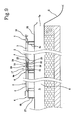
- coupling means 17 is operatively disposed between the solar panels 2 so as to make this connection between them steady in a coupled configuration corresponding to the fitting-out configuration of kit 1.
- the coupling means 17 is disposed between the support frames 4 of the solar panels 2.
- the section shape of the support frames 4 defines said coupling means 17.
- each support frame 4 comprises a first side 4a and a second side 4b parallel and opposite to the first side 4a.
- the first side 4a of each support frame 4 is placed downstream of the second side 4b with reference to the descending direction of the roof pitch.
- the support frame 4 comprises a tailpiece 18 extending along the first side 4a, preferably along the whole first side 4a.
- This tailpiece 18 extends along a lying plane of the solar panel 2 away from the solar panel 2 itself.
- this first side 4a is defined by a main tubular portion giving stiffness to the support frame 4.
- tailpiece 18 is of one piece construction with the main tubular portion 19 and extends away therefrom.
- a recess 31 is disposed between the tailpiece 18 and the main tubular portion 19 for receiving modules 3.
- a seat 20 is formed along the second side 4b of the support frame 4 for receiving and supporting the tailpiece 18 of the first side 4a of the adjacent solar panel 2 and in particular the upstream solar panel.
- each support frame 4 comprises a main tubular portion 21 giving the appropriate structural stiffness and an auxiliary tubular portion 22 fastened to or of one piece construction with the main tubular portion 21.
- a recess 32 unitary with the main tubular portion 21 is defined for housing modules 3.
- the auxiliary tubular portion 22 externally defines a preferably flat rest surface 22a, and lying thereon is the tailpiece 18 of the first side 4a of the solar panel placed upstream in the coupled configuration.
- the rest surface 22a preferably extends along the whole second side 4b. For this reason, the rest surface 22a partly defines said seat 20.
- an abutment shoulder 23 is fastened to or is of one piece construction with the main tubular portion 21 of the second side 4b of the support frame 4.
- said abutment shoulder 23 is placed between the main tubular portion 21 and the auxiliary tubular portion 22.
- the abutment shoulder 23 is defined by a flap extending transversely of the lying plane of the solar panel 2 and at least away from the auxiliary tubular portion 22. In other words, the abutment shoulder 23 substantially lies transversely of and preferably orthogonal to the rest surface 22a.
- the abutment shoulder 23 defines a retainer for the tailpiece 18 of the first side 4a of the support frame 4 placed upstream. Consequently, the abutment shoulder 23 together with the rest surface 22a define said seat 20.
- Kit 1 further comprise sealing means 24 operatively disposed between the tailpieces 18 and seats 20 in such a manner as to reduce and ultimately eliminate water seepage between the solar panels 2 coupled along the successions.
- the sealing means 24 comprises a seal 25 connected to each tailpiece 18.
- This seal 25 has an active surface disposed orthogonal to the extension of the tailpiece 18 itself.
- this seal 25 has an active surface disposed orthogonal to the lying plane of the solar panel 2.
- this active surface of seal 25 is in contact with the abutment shoulder 23. It is to be pointed out that the pressure exerted by this seal 25 on the abutment surface 23 and necessary for ensuring the hydraulic tightness, is guaranteed by the weight of the upstream solar panel 2 pushing the tailpiece 18 and seal 25 against the seat 20 of the downstream solar panel 2, being said solar panels 2 mounted on the inclined plane of the roof pitch.
- the sealing means 24 further comprises an additional seal 26 connected to each tailpiece 18.
- This additional seal 26 has an active surface disposed parallel to the extension of the tailpiece 18 itself. In other words, this additional seal 26 has an active surface disposed parallel to the lying plane of the solar panel 2.
- this active surface of the additional seal 26 is in contact with the rest surface 22a of the auxiliary tubular portion 22 of the second side 4b.
- This additional seal 26 advantageously ensures creation of a further barrier to water seepage between adjacent solar panels 2, above all when the inclination of the roof pitch is not sufficient to powerfully press seal 25 against the abutment shoulder 23.
- Each support frame 4 further has third and fourth sides 4c parallel to each other and meeting and joining the first 4a and second 4b sides. These third and fourth sides 4c lie on the rest portions 5b of the support bars 5 in the fitting-out configuration of kit 1.
- each third and fourth side 4c has a tubular portion 29 giving appropriate structural stiffness and a recess 33 for the coating plate D for housing modules 3.
- the third and fourth sides 4c each further have a tab 30 extending orthogonal to the lying plane of the solar panel 2 away from recess 33.
- This tab 30 preferably extending along the whole of the third and fourth sides 4c, is disposed in the fitting-out configuration towards the bottom wall 8 of the support bars 5 for coming into contact with the bent free edges 9a of the side walls 9. In this manner, the solar panels are maintained in the correct position.
- Kit 1 further comprises two retaining elements 27, 28 that can be positioned upstream of the first solar panel 2 of the succession and downstream of the last solar panel 2 of the succession.
- first solar panel 2 of the succession it is intended the solar panel 2 placed at a ridge "V" of the roof, and by “last solar panel 2 of the succession” it is intended the solar panel 2 placed close to gutter "G".
- the retaining elements 27, 28 comprise at least one L-shaped portion, enabling them to be fastened to the roof beams on one side and brought into contact with the first 4a and the second 4b sides of the support frames 4, respectively.
- a first retaining element 27 is designed to be fastened to the roof at the roof ridge "V". This first retaining element 27 in this case is in contact with the second side 4b of the support frames 4 of the first solar panels 2 of the succession.
- a second retaining element 28, in the fitting-out configuration of the kit, is designed to be fastened to the roof at gutter "G".
- This second retaining element 28 in this case is in contact with the first side 4a of the support frames 4 of the last solar panels 2 of the succession.
- the retaining elements 27, 28 are preferably made of sheet metal.
- fastening portions 5a are secured to beams "T" by means of screws, for example.
- the support bars 5 are fastened to the beams in such a manner that an end thereof defining the outflow section 7a of drain 7 faces gutter "G".
- the solar panels 2 are laid on the support bars 5.
- the support frames 4 are laid on the rest portions 5b.
- the third and fourth sides 4c of the support frames 4 are laid on the rest portions 5b.
- the step of laying down the solar panels 2 is done by fastening the second retaining element 28 close to gutter "G" and then laying the solar panel 2 upstream of the second retaining element 28.
- a subsequent solar panel 2 is disposed adjacent to, and in particular upstream of the just laid down panel and in such a manner that the tailpiece 18 of the upstream solar panel is frictionally fitted into the seat 20 of the downstream solar panel 2.
- the locking bodies 10 are connected to the respective support bars 5 in such a manner that the coating elements 11 push the support frames 4 against the rest portions 5b to keep the solar panels 2 in position.
- the invention reaches the intended purpose and achieves important advantages.
- the solar panels are mounted between the support bars and the locking bodies, a barrier is defined against water seepage exactly between the support frames of the solar panels and the coating elements.
Landscapes
- Engineering & Computer Science (AREA)
- Chemical & Material Sciences (AREA)
- Physics & Mathematics (AREA)
- Life Sciences & Earth Sciences (AREA)
- Sustainable Development (AREA)
- Sustainable Energy (AREA)
- Thermal Sciences (AREA)
- Combustion & Propulsion (AREA)
- Mechanical Engineering (AREA)
- General Engineering & Computer Science (AREA)
- Civil Engineering (AREA)
- Structural Engineering (AREA)
- Architecture (AREA)
- Roof Covering Using Slabs Or Stiff Sheets (AREA)
Claims (6)
- Kit pour monter un toit photovoltaïque, comprenant :- une pluralité de panneaux solaires (2) pouvant être disposés en une ou plusieurs files ou rangées disposées le long d'une direction inclinée d'une pente de toiture, chaque panneau solaire (2) ayant un cadre de support (4) disposé en périphérie ;- au moins deux barres de support (5), chacune se développant le long d'un axe d'extension principal et chacune comprenant une partie de fixation (5a) pouvant s'accoupler à une poutrelle le long d'une direction inclinée d'une pente de toiture et deux parties d'appui (5b) reliées à ladite partie de fixation (5a) le long des côtés opposés, chaque partie d'appui (5b) pouvant respectivement recevoir deux éléments intermédiaires, dont l'un au moins définit un côté correspondant dudit cadre de support (4) d'un panneau solaire (2) ; chaque barre de support (5) pouvant être disposée entre deux files de panneaux solaires (2) ou entre une file de panneaux solaires (2) et une volige (6),dans lequel le kit comprend au moins deux corps de verrouillage (10) fabriqués dans un matériau plastique flexible, chacun se développant le long d'un axe d'extension principal, tous deux pouvant se raccorder à une barre de support (5) correspondante et comprenant un élément de revêtement (11) ;
dans lequel chaque barre de support (5) et chaque corps de verrouillage (10) possèdent des organes de liaison (12) du type à encliquetage pour raccorder chaque corps de verrouillage (10) à la barre de support correspondante (5) ;
dans lequel chaque élément de revêtement (11) est configuré pour être disposé en contact avec les éléments intermédiaires respectifs dans une position située à l'opposé desdites parties d'appui (5b) dans une configuration raccordée de chaque corps de verrouillage (10) avec la barre de support correspondante (5), chaque élément de revêtement (11) pouvant être disposé entre deux files de panneaux solaires (2) ou entre une file de panneaux solaires (2) et une volige (6), et étant configuré pour pousser, lesdits éléments intermédiaires, contre les parties d'appui correspondantes (5b) afin de maintenir en place lesdits panneaux solaires (2) ou ladite volige (6),
dans lequel chaque barre de support (5) comprend au moins une paroi inférieure (8) qui sera accouplée à la poutrelle et définissant au moins en partie ladite partie de fixation (5a), et deux parois latérales (9) dépassant de ladite paroi inférieure (8) ;
dans lequel chaque paroi latérale (9) de chaque barre de support (5) possède un bord libre (9a) situé à l'opposé de la paroi inférieure (8) et plié vers l'autre paroi latérale (9), les bords libres pliés (9a) étant coplanaires les uns aux autres pour définir une surface d'appui des parties d'appui (5b),
dans lequel chaque barre de support (5) possède une section transversale essentiellement creuse pour définir une canalisation d'eau (7) définie par la paroi inférieure (8) en coopération avec les parois latérales (9),
dans lequel les éléments intermédiaires restant dans la configuration de montage sur les parties d'appui (5b) des barres de support (5) se trouvent face à la canalisation (7), où l'eau qui s'infiltre est acheminée dans ladite canalisation pour être évacuée,
dans lequel les éléments intermédiaires du panneau solaire (2) possèdent de plus une languette (30) se développant de façon orthogonale par rapport au plan d'appui du panneau solaire (2) le long de l'axe d'extension principal et disposée dans la configuration de montage vers la paroi inférieure (8) des barres de support (5) pour venir en contact avec les bords libres pliés (9a) des parois latérales (9),
caractérisé en ce que le kit comprend de plus :des moyens d'accouplement (17) disposés entre des panneaux solaires adjacents (2) d'une file de sorte à raccorder un panneau solaire (2) à un panneau solaire adjacent (2) dans une configuration couplée comprenant un about (18) placé le long d'au moins un premier côté (4a) dudit cadre de support (4) et se développant le long d'un plan d'appui dudit panneau solaire (2) à l'extrémité dudit panneau solaire (2), et un siège (20) disposé le long d'au moins un second côté (4b), opposé au premier côté, pour recevoir ledit about (18) d'un panneau solaire adjacent (2) en appui sur celui-ci, ledit siège (20) étant défini par un épaulement de butée (23) avec une surface d'appui (22a) du second côté (4b),l'épaulement de butée (23) définissant une retenue pour l'about (18) du premier côté (4a) du cadre de support (4) placée en amont en se référant à la direction descendante de la pente de toitureet dans lequel un moyen d'isolation (24) fonctionnellement disposé entre ledit about (18) d'un panneau solaire (2) et ledit siège (20) d'un panneau solaire adjacent (2) comprend un scellement (25) raccordé à l'about (18) ayant une surface active disposée de façon orthogonale par rapport au plan d'appui du panneau solaire (2) et configurée pour être en contact avec l'épaulement de butée (23) dans la configuration couplée,dans lequel ledit moyen d'isolation (24) comprend de plus un scellement supplémentaire (26) relié à l'about (18) ayant une surface active disposée de façon parallèle par rapport au plan d'appui du panneau solaire (2) et configurée pour être en contact avec la surface de repos (22a) du second côté (4b) dans la configuration couplée etdans lequel l'about (18) et le scellement (25) sont disposés pour être poussés contre le siège (20) du panneau situé en aval (2) en se référant à la direction descendante de la pente de toiture. - Kit selon la revendication 1, caractérisé en ce que chaque élément de revêtement (11) possède une section transversale comprenant au moins une partie intermédiaire arquée (11a) dont la concavité se trouve face à ladite barre de support (5) ; ladite section transversale comprenant de plus des parties latérales arquées (11b) dont la concavité se trouve à l'opposé de celle de ladite partie intermédiaire arquée (11a) et disposée le long des côtés situés à l'opposé de ladite partie intermédiaire arquée (11a) ; lesdites parties latérales arquées (11b) étant en contact avec lesdits éléments intermédiaires dans ladite configuration raccordée.
- Kit selon la revendication 1, caractérisé en ce que lesdits organes de liaison (12) comprennent au moins une ailette (13) reliée de manière élastique au dit élément de revêtement (11) et ayant une dent (14) située à l'extrémité de cette dernière ; lesdits organes de liaison (12) comprenant de plus un about (15) dépassant de ladite paroi inférieure (8) et possédant un dégagement (16) pour accueillir ladite dent (14) dans la configuration raccordée.
- Kit selon la revendication 1, caractérisé en ce que ledit premier côté (4a) dudit cadre de support (4) comprend une partie tubulaire principale (19) ; ledit about (18) formant un seul tenant avec ladite partie tubulaire (19) et se développant à partir de cette dernière.
- Kit selon la revendication 1, caractérisé en ce que ledit second côté (4b) dudit cadre de support (4) comprend une partie tubulaire principale (21) et l'épaulement de butée (23) se développant essentiellement transversalement par rapport au dit plan d'appui.
- Kit selon l'une des revendications 4 ou 5, caractérisé en ce qu'il comprend de plus deux éléments de retenue (27, 28) pouvant être associés au dit premier côté dudit cadre de support (4) d'un premier panneau solaire (2) dans ladite file et au dit second côté (4b) dudit cadre de support (4) d'un dernier panneau solaire (2) dans ladite file.
Priority Applications (1)
| Application Number | Priority Date | Filing Date | Title |
|---|---|---|---|
| EP11425124A EP2520876B1 (fr) | 2011-05-04 | 2011-05-04 | Kit pour monter un toit photovoltaïque |
Applications Claiming Priority (1)
| Application Number | Priority Date | Filing Date | Title |
|---|---|---|---|
| EP11425124A EP2520876B1 (fr) | 2011-05-04 | 2011-05-04 | Kit pour monter un toit photovoltaïque |
Publications (2)
| Publication Number | Publication Date |
|---|---|
| EP2520876A1 EP2520876A1 (fr) | 2012-11-07 |
| EP2520876B1 true EP2520876B1 (fr) | 2013-04-03 |
Family
ID=44675514
Family Applications (1)
| Application Number | Title | Priority Date | Filing Date |
|---|---|---|---|
| EP11425124A Not-in-force EP2520876B1 (fr) | 2011-05-04 | 2011-05-04 | Kit pour monter un toit photovoltaïque |
Country Status (1)
| Country | Link |
|---|---|
| EP (1) | EP2520876B1 (fr) |
Cited By (1)
| Publication number | Priority date | Publication date | Assignee | Title |
|---|---|---|---|---|
| CN106911299A (zh) * | 2017-02-23 | 2017-06-30 | 迈贝特(厦门)新能源有限公司 | 一种太阳能板组装结构和固定边框 |
Families Citing this family (8)
| Publication number | Priority date | Publication date | Assignee | Title |
|---|---|---|---|---|
| JP6317142B2 (ja) * | 2014-03-11 | 2018-04-25 | 京セラ株式会社 | 屋根材型アレイ |
| TWI575864B (zh) * | 2015-03-23 | 2017-03-21 | 上銀光電股份有限公司 | 太陽能板模組之強化結構 |
| CN105099343B (zh) * | 2015-07-23 | 2017-11-10 | 北京汉能光伏投资有限公司 | 一种太阳能薄膜发电铝合金瓦 |
| GB2541927A (en) | 2015-09-04 | 2017-03-08 | Viridian Concepts Ltd | Photovoltaic roof covering |
| US10547270B2 (en) | 2016-02-12 | 2020-01-28 | Solarcity Corporation | Building integrated photovoltaic roofing assemblies and associated systems and methods |
| CN106836884B (zh) * | 2017-02-23 | 2019-04-23 | 迈贝特(厦门)新能源有限公司 | 一种防水太阳能车棚 |
| NO347591B1 (no) * | 2020-11-20 | 2024-01-22 | Isola Solar As | System for innfesting av solceller på tak eller veggfasader |
| CN119221604B (zh) * | 2024-09-06 | 2025-05-30 | 山东建筑大学 | 一种装配式光伏建筑一体化大跨度空间结构体系及方法 |
Citations (4)
| Publication number | Priority date | Publication date | Assignee | Title |
|---|---|---|---|---|
| EP0424581A1 (fr) * | 1989-10-23 | 1991-05-02 | Hirai Engineering Corporation | Toit |
| US5706617A (en) * | 1992-11-19 | 1998-01-13 | Hirai Engineering Corporation | Roof system utilizing a solar cell |
| DE202009005145U1 (de) * | 2009-08-14 | 2009-10-29 | Solarwatt Ag | Photovoltaisches Solarmodul mit Indach-Rahmen als Indach-Solarsystemanordnung |
| EP2354718A2 (fr) * | 2010-02-04 | 2011-08-10 | Solergie (Qingdao) Renewable Energy Co., Ltd. | Bloc d'intégration pour module à énergie solaire et toiture comprenant de tels blocs |
Family Cites Families (8)
| Publication number | Priority date | Publication date | Assignee | Title |
|---|---|---|---|---|
| US6105317A (en) * | 1997-09-24 | 2000-08-22 | Matsushita Electric Works, Ltd. | Mounting system for installing an array of solar battery modules of a panel-like configuration on a roof |
| JPH11222991A (ja) * | 1998-02-06 | 1999-08-17 | Kyocera Corp | 採光体の固定構造 |
| JPH11324241A (ja) * | 1998-05-20 | 1999-11-26 | Misawa Homes Co Ltd | 棟カバー取付構造 |
| EP1341240B1 (fr) * | 2000-11-16 | 2016-11-02 | Kaneka Corporation | Module de batterie solaire, systeme de production d'energie photovoltaique, bloc de support supportant ce module de batterie solaire |
| FR2934616B1 (fr) * | 2008-08-04 | 2013-05-10 | Concept Alu | Structure de toiture constituee de chevrons paralleles munis de feuillures laterales pour la reception de panneaux de remplissage. |
| JP2011038384A (ja) * | 2009-08-18 | 2011-02-24 | Kaname:Kk | 屋根用パネル及び屋根用パネルの取り付け構造 |
| FR2949521A1 (fr) * | 2009-08-26 | 2011-03-04 | Actif En Vertes | Dispositif de fixation d'au moins un panneau sur une structure porteuse |
| JP5419595B2 (ja) * | 2009-08-31 | 2014-02-19 | 三晃金属工業株式会社 | 太陽光発電装置 |
-
2011
- 2011-05-04 EP EP11425124A patent/EP2520876B1/fr not_active Not-in-force
Patent Citations (4)
| Publication number | Priority date | Publication date | Assignee | Title |
|---|---|---|---|---|
| EP0424581A1 (fr) * | 1989-10-23 | 1991-05-02 | Hirai Engineering Corporation | Toit |
| US5706617A (en) * | 1992-11-19 | 1998-01-13 | Hirai Engineering Corporation | Roof system utilizing a solar cell |
| DE202009005145U1 (de) * | 2009-08-14 | 2009-10-29 | Solarwatt Ag | Photovoltaisches Solarmodul mit Indach-Rahmen als Indach-Solarsystemanordnung |
| EP2354718A2 (fr) * | 2010-02-04 | 2011-08-10 | Solergie (Qingdao) Renewable Energy Co., Ltd. | Bloc d'intégration pour module à énergie solaire et toiture comprenant de tels blocs |
Cited By (1)
| Publication number | Priority date | Publication date | Assignee | Title |
|---|---|---|---|---|
| CN106911299A (zh) * | 2017-02-23 | 2017-06-30 | 迈贝特(厦门)新能源有限公司 | 一种太阳能板组装结构和固定边框 |
Also Published As
| Publication number | Publication date |
|---|---|
| EP2520876A1 (fr) | 2012-11-07 |
Similar Documents
| Publication | Publication Date | Title |
|---|---|---|
| EP2520876B1 (fr) | Kit pour monter un toit photovoltaïque | |
| US7721492B2 (en) | Strut runner member and assembly using same for mounting arrays on rooftops and other structures | |
| EP2169139B1 (fr) | Structure de fixation d'un module de batterie solaire, cadre pour le module de batterie solaire, et élément de fixation | |
| US8495839B2 (en) | Installation structure of solar cell module | |
| US10270382B2 (en) | Panel, assembly of panels and associated roof | |
| WO2010128375A2 (fr) | Joint profilé pour raccorder des panneaux solaires | |
| DK3074578T3 (en) | Panel, panel assembly and associated roof | |
| US20140196769A1 (en) | Mounting structures for photovoltaic cells | |
| KR20070114065A (ko) | 태양광 지붕 타일 | |
| US20120272591A1 (en) | Device for generating solar power | |
| GB2466003A (en) | Securing A Solar Energy Collection Device As Part Of A Roof | |
| US20150129016A1 (en) | Modular roof solar panel for conventional roof and roofing integration | |
| EP3319228A1 (fr) | Panneau solaire intégré à un toit en tuiles | |
| US20120132260A1 (en) | Assembly, Sub-Structure and Photovoltaic System | |
| JP6746369B2 (ja) | 太陽電池モジュール | |
| US20240084591A1 (en) | Roofing systems, roofing systems with integrated solar racking systems, roofing system components, and related methods | |
| EP4150757B1 (fr) | Système et procédé de liaison et de fixation de panneaux solaires encadrés pour fabriquer une surface modulaire intégrée à un bâtiment résistante aux intempéries | |
| CZ309498A3 (cs) | Fotoelektrický systém pro šikmou střechu | |
| US20080276552A1 (en) | Adaptor | |
| AU2015203159A1 (en) | Photovoltaic assembly | |
| JP2005307693A (ja) | 太陽電池モジュールおよび太陽電池モジュール設置構造 | |
| SE546899C2 (en) | System for fastening solar cells to roofs or wall facades of buildnings and a method | |
| EP2757592A1 (fr) | Système de montage pour modules photovoltaïques et composants en forme de plaque | |
| CN111699626B (zh) | 太阳能电池模块及太阳能发电系统 | |
| US20120312350A1 (en) | Solar cell roof system having a plurality of solar modules |
Legal Events
| Date | Code | Title | Description |
|---|---|---|---|
| PUAI | Public reference made under article 153(3) epc to a published international application that has entered the european phase |
Free format text: ORIGINAL CODE: 0009012 |
|
| 17P | Request for examination filed |
Effective date: 20120130 |
|
| AK | Designated contracting states |
Kind code of ref document: A1 Designated state(s): AL AT BE BG CH CY CZ DE DK EE ES FI FR GB GR HR HU IE IS IT LI LT LU LV MC MK MT NL NO PL PT RO RS SE SI SK SM TR |
|
| AX | Request for extension of the european patent |
Extension state: BA ME |
|
| REG | Reference to a national code |
Ref country code: DE Ref legal event code: R079 Ref document number: 602011001257 Country of ref document: DE Free format text: PREVIOUS MAIN CLASS: F24J0002520000 Ipc: F24J0002040000 |
|
| GRAP | Despatch of communication of intention to grant a patent |
Free format text: ORIGINAL CODE: EPIDOSNIGR1 |
|
| RIC1 | Information provided on ipc code assigned before grant |
Ipc: H01L 31/042 20060101ALI20121203BHEP Ipc: F24J 2/04 20060101AFI20121203BHEP |
|
| GRAS | Grant fee paid |
Free format text: ORIGINAL CODE: EPIDOSNIGR3 |
|
| GRAA | (expected) grant |
Free format text: ORIGINAL CODE: 0009210 |
|
| AK | Designated contracting states |
Kind code of ref document: B1 Designated state(s): AL AT BE BG CH CY CZ DE DK EE ES FI FR GB GR HR HU IE IS IT LI LT LU LV MC MK MT NL NO PL PT RO RS SE SI SK SM TR |
|
| REG | Reference to a national code |
Ref country code: GB Ref legal event code: FG4D |
|
| REG | Reference to a national code |
Ref country code: AT Ref legal event code: REF Ref document number: 604987 Country of ref document: AT Kind code of ref document: T Effective date: 20130415 Ref country code: CH Ref legal event code: EP |
|
| REG | Reference to a national code |
Ref country code: IE Ref legal event code: FG4D |
|
| REG | Reference to a national code |
Ref country code: DE Ref legal event code: R096 Ref document number: 602011001257 Country of ref document: DE Effective date: 20130529 |
|
| REG | Reference to a national code |
Ref country code: AT Ref legal event code: MK05 Ref document number: 604987 Country of ref document: AT Kind code of ref document: T Effective date: 20130403 Ref country code: CH Ref legal event code: NV Representative=s name: BUGNION S.A., CH |
|
| PG25 | Lapsed in a contracting state [announced via postgrant information from national office to epo] |
Ref country code: SI Free format text: LAPSE BECAUSE OF FAILURE TO SUBMIT A TRANSLATION OF THE DESCRIPTION OR TO PAY THE FEE WITHIN THE PRESCRIBED TIME-LIMIT Effective date: 20130403 |
|
| REG | Reference to a national code |
Ref country code: NL Ref legal event code: VDEP Effective date: 20130403 |
|
| REG | Reference to a national code |
Ref country code: LT Ref legal event code: MG4D |
|
| PG25 | Lapsed in a contracting state [announced via postgrant information from national office to epo] |
Ref country code: ES Free format text: LAPSE BECAUSE OF FAILURE TO SUBMIT A TRANSLATION OF THE DESCRIPTION OR TO PAY THE FEE WITHIN THE PRESCRIBED TIME-LIMIT Effective date: 20130714 Ref country code: LT Free format text: LAPSE BECAUSE OF FAILURE TO SUBMIT A TRANSLATION OF THE DESCRIPTION OR TO PAY THE FEE WITHIN THE PRESCRIBED TIME-LIMIT Effective date: 20130403 Ref country code: AT Free format text: LAPSE BECAUSE OF FAILURE TO SUBMIT A TRANSLATION OF THE DESCRIPTION OR TO PAY THE FEE WITHIN THE PRESCRIBED TIME-LIMIT Effective date: 20130403 Ref country code: IS Free format text: LAPSE BECAUSE OF FAILURE TO SUBMIT A TRANSLATION OF THE DESCRIPTION OR TO PAY THE FEE WITHIN THE PRESCRIBED TIME-LIMIT Effective date: 20130803 Ref country code: NO Free format text: LAPSE BECAUSE OF FAILURE TO SUBMIT A TRANSLATION OF THE DESCRIPTION OR TO PAY THE FEE WITHIN THE PRESCRIBED TIME-LIMIT Effective date: 20130703 Ref country code: PT Free format text: LAPSE BECAUSE OF FAILURE TO SUBMIT A TRANSLATION OF THE DESCRIPTION OR TO PAY THE FEE WITHIN THE PRESCRIBED TIME-LIMIT Effective date: 20130805 Ref country code: FI Free format text: LAPSE BECAUSE OF FAILURE TO SUBMIT A TRANSLATION OF THE DESCRIPTION OR TO PAY THE FEE WITHIN THE PRESCRIBED TIME-LIMIT Effective date: 20130403 Ref country code: SE Free format text: LAPSE BECAUSE OF FAILURE TO SUBMIT A TRANSLATION OF THE DESCRIPTION OR TO PAY THE FEE WITHIN THE PRESCRIBED TIME-LIMIT Effective date: 20130403 Ref country code: NL Free format text: LAPSE BECAUSE OF FAILURE TO SUBMIT A TRANSLATION OF THE DESCRIPTION OR TO PAY THE FEE WITHIN THE PRESCRIBED TIME-LIMIT Effective date: 20130403 Ref country code: GR Free format text: LAPSE BECAUSE OF FAILURE TO SUBMIT A TRANSLATION OF THE DESCRIPTION OR TO PAY THE FEE WITHIN THE PRESCRIBED TIME-LIMIT Effective date: 20130704 Ref country code: BE Free format text: LAPSE BECAUSE OF FAILURE TO SUBMIT A TRANSLATION OF THE DESCRIPTION OR TO PAY THE FEE WITHIN THE PRESCRIBED TIME-LIMIT Effective date: 20130403 |
|
| PG25 | Lapsed in a contracting state [announced via postgrant information from national office to epo] |
Ref country code: BG Free format text: LAPSE BECAUSE OF FAILURE TO SUBMIT A TRANSLATION OF THE DESCRIPTION OR TO PAY THE FEE WITHIN THE PRESCRIBED TIME-LIMIT Effective date: 20130703 Ref country code: LV Free format text: LAPSE BECAUSE OF FAILURE TO SUBMIT A TRANSLATION OF THE DESCRIPTION OR TO PAY THE FEE WITHIN THE PRESCRIBED TIME-LIMIT Effective date: 20130403 Ref country code: CY Free format text: LAPSE BECAUSE OF FAILURE TO SUBMIT A TRANSLATION OF THE DESCRIPTION OR TO PAY THE FEE WITHIN THE PRESCRIBED TIME-LIMIT Effective date: 20130403 Ref country code: RS Free format text: LAPSE BECAUSE OF FAILURE TO SUBMIT A TRANSLATION OF THE DESCRIPTION OR TO PAY THE FEE WITHIN THE PRESCRIBED TIME-LIMIT Effective date: 20130403 Ref country code: HR Free format text: LAPSE BECAUSE OF FAILURE TO SUBMIT A TRANSLATION OF THE DESCRIPTION OR TO PAY THE FEE WITHIN THE PRESCRIBED TIME-LIMIT Effective date: 20130403 Ref country code: PL Free format text: LAPSE BECAUSE OF FAILURE TO SUBMIT A TRANSLATION OF THE DESCRIPTION OR TO PAY THE FEE WITHIN THE PRESCRIBED TIME-LIMIT Effective date: 20130403 |
|
| PG25 | Lapsed in a contracting state [announced via postgrant information from national office to epo] |
Ref country code: EE Free format text: LAPSE BECAUSE OF FAILURE TO SUBMIT A TRANSLATION OF THE DESCRIPTION OR TO PAY THE FEE WITHIN THE PRESCRIBED TIME-LIMIT Effective date: 20130403 Ref country code: MC Free format text: LAPSE BECAUSE OF FAILURE TO SUBMIT A TRANSLATION OF THE DESCRIPTION OR TO PAY THE FEE WITHIN THE PRESCRIBED TIME-LIMIT Effective date: 20130403 Ref country code: DK Free format text: LAPSE BECAUSE OF FAILURE TO SUBMIT A TRANSLATION OF THE DESCRIPTION OR TO PAY THE FEE WITHIN THE PRESCRIBED TIME-LIMIT Effective date: 20130403 Ref country code: CZ Free format text: LAPSE BECAUSE OF FAILURE TO SUBMIT A TRANSLATION OF THE DESCRIPTION OR TO PAY THE FEE WITHIN THE PRESCRIBED TIME-LIMIT Effective date: 20130403 Ref country code: SK Free format text: LAPSE BECAUSE OF FAILURE TO SUBMIT A TRANSLATION OF THE DESCRIPTION OR TO PAY THE FEE WITHIN THE PRESCRIBED TIME-LIMIT Effective date: 20130403 |
|
| PLBE | No opposition filed within time limit |
Free format text: ORIGINAL CODE: 0009261 |
|
| STAA | Information on the status of an ep patent application or granted ep patent |
Free format text: STATUS: NO OPPOSITION FILED WITHIN TIME LIMIT |
|
| REG | Reference to a national code |
Ref country code: IE Ref legal event code: MM4A |
|
| PG25 | Lapsed in a contracting state [announced via postgrant information from national office to epo] |
Ref country code: RO Free format text: LAPSE BECAUSE OF FAILURE TO SUBMIT A TRANSLATION OF THE DESCRIPTION OR TO PAY THE FEE WITHIN THE PRESCRIBED TIME-LIMIT Effective date: 20130403 |
|
| 26N | No opposition filed |
Effective date: 20140106 |
|
| REG | Reference to a national code |
Ref country code: DE Ref legal event code: R097 Ref document number: 602011001257 Country of ref document: DE Effective date: 20140106 |
|
| PG25 | Lapsed in a contracting state [announced via postgrant information from national office to epo] |
Ref country code: IE Free format text: LAPSE BECAUSE OF NON-PAYMENT OF DUE FEES Effective date: 20130504 |
|
| PGFP | Annual fee paid to national office [announced via postgrant information from national office to epo] |
Ref country code: DE Payment date: 20140429 Year of fee payment: 4 Ref country code: IT Payment date: 20140531 Year of fee payment: 4 Ref country code: CH Payment date: 20140430 Year of fee payment: 4 |
|
| PGFP | Annual fee paid to national office [announced via postgrant information from national office to epo] |
Ref country code: FR Payment date: 20140429 Year of fee payment: 4 |
|
| PG25 | Lapsed in a contracting state [announced via postgrant information from national office to epo] |
Ref country code: MT Free format text: LAPSE BECAUSE OF FAILURE TO SUBMIT A TRANSLATION OF THE DESCRIPTION OR TO PAY THE FEE WITHIN THE PRESCRIBED TIME-LIMIT Effective date: 20130403 |
|
| PG25 | Lapsed in a contracting state [announced via postgrant information from national office to epo] |
Ref country code: SM Free format text: LAPSE BECAUSE OF FAILURE TO SUBMIT A TRANSLATION OF THE DESCRIPTION OR TO PAY THE FEE WITHIN THE PRESCRIBED TIME-LIMIT Effective date: 20130403 |
|
| PG25 | Lapsed in a contracting state [announced via postgrant information from national office to epo] |
Ref country code: TR Free format text: LAPSE BECAUSE OF FAILURE TO SUBMIT A TRANSLATION OF THE DESCRIPTION OR TO PAY THE FEE WITHIN THE PRESCRIBED TIME-LIMIT Effective date: 20130403 |
|
| PG25 | Lapsed in a contracting state [announced via postgrant information from national office to epo] |
Ref country code: HU Free format text: LAPSE BECAUSE OF FAILURE TO SUBMIT A TRANSLATION OF THE DESCRIPTION OR TO PAY THE FEE WITHIN THE PRESCRIBED TIME-LIMIT; INVALID AB INITIO Effective date: 20110504 Ref country code: MK Free format text: LAPSE BECAUSE OF FAILURE TO SUBMIT A TRANSLATION OF THE DESCRIPTION OR TO PAY THE FEE WITHIN THE PRESCRIBED TIME-LIMIT Effective date: 20130403 Ref country code: LU Free format text: LAPSE BECAUSE OF NON-PAYMENT OF DUE FEES Effective date: 20130504 |
|
| REG | Reference to a national code |
Ref country code: DE Ref legal event code: R119 Ref document number: 602011001257 Country of ref document: DE |
|
| REG | Reference to a national code |
Ref country code: CH Ref legal event code: PL |
|
| GBPC | Gb: european patent ceased through non-payment of renewal fee |
Effective date: 20150504 |
|
| PG25 | Lapsed in a contracting state [announced via postgrant information from national office to epo] |
Ref country code: LI Free format text: LAPSE BECAUSE OF NON-PAYMENT OF DUE FEES Effective date: 20150531 Ref country code: CH Free format text: LAPSE BECAUSE OF NON-PAYMENT OF DUE FEES Effective date: 20150531 Ref country code: IT Free format text: LAPSE BECAUSE OF NON-PAYMENT OF DUE FEES Effective date: 20150504 |
|
| REG | Reference to a national code |
Ref country code: FR Ref legal event code: ST Effective date: 20160129 |
|
| PG25 | Lapsed in a contracting state [announced via postgrant information from national office to epo] |
Ref country code: GB Free format text: LAPSE BECAUSE OF NON-PAYMENT OF DUE FEES Effective date: 20150504 Ref country code: DE Free format text: LAPSE BECAUSE OF NON-PAYMENT OF DUE FEES Effective date: 20151201 |
|
| PG25 | Lapsed in a contracting state [announced via postgrant information from national office to epo] |
Ref country code: FR Free format text: LAPSE BECAUSE OF NON-PAYMENT OF DUE FEES Effective date: 20150601 |
|
| PG25 | Lapsed in a contracting state [announced via postgrant information from national office to epo] |
Ref country code: AL Free format text: LAPSE BECAUSE OF FAILURE TO SUBMIT A TRANSLATION OF THE DESCRIPTION OR TO PAY THE FEE WITHIN THE PRESCRIBED TIME-LIMIT Effective date: 20130403 |