EP2520897B1 - Aéronef pourvu d'un système de lancement pour le lancement de bougies fumigènes - Google Patents
Aéronef pourvu d'un système de lancement pour le lancement de bougies fumigènes Download PDFInfo
- Publication number
- EP2520897B1 EP2520897B1 EP20120166744 EP12166744A EP2520897B1 EP 2520897 B1 EP2520897 B1 EP 2520897B1 EP 20120166744 EP20120166744 EP 20120166744 EP 12166744 A EP12166744 A EP 12166744A EP 2520897 B1 EP2520897 B1 EP 2520897B1
- Authority
- EP
- European Patent Office
- Prior art keywords
- barrel
- connection member
- gun
- aircraft
- aircraft according
- Prior art date
- Legal status (The legal status is an assumption and is not a legal conclusion. Google has not performed a legal analysis and makes no representation as to the accuracy of the status listed.)
- Active
Links
Images




Classifications
-
- F—MECHANICAL ENGINEERING; LIGHTING; HEATING; WEAPONS; BLASTING
- F42—AMMUNITION; BLASTING
- F42B—EXPLOSIVE CHARGES, e.g. FOR BLASTING, FIREWORKS, AMMUNITION
- F42B5/00—Cartridge ammunition, e.g. separately-loaded propellant charges
- F42B5/02—Cartridges, i.e. cases with charge and missile
- F42B5/145—Cartridges, i.e. cases with charge and missile for dispensing gases, vapours, powders, particles or chemically-reactive substances
- F42B5/15—Cartridges, i.e. cases with charge and missile for dispensing gases, vapours, powders, particles or chemically-reactive substances for creating a screening or decoy effect, e.g. using radar chaff or infrared material
- F42B5/155—Smoke-pot projectors, e.g. arranged on vehicles
-
- B—PERFORMING OPERATIONS; TRANSPORTING
- B64—AIRCRAFT; AVIATION; COSMONAUTICS
- B64D—EQUIPMENT FOR FITTING IN OR TO AIRCRAFT; FLIGHT SUITS; PARACHUTES; ARRANGEMENT OR MOUNTING OF POWER PLANTS OR PROPULSION TRANSMISSIONS IN AIRCRAFT
- B64D1/00—Dropping, ejecting, releasing or receiving articles, liquids, or the like, in flight
- B64D1/02—Dropping, ejecting, or releasing articles
- B64D1/04—Dropping, ejecting, or releasing articles the articles being explosive, e.g. bombs
-
- B—PERFORMING OPERATIONS; TRANSPORTING
- B64—AIRCRAFT; AVIATION; COSMONAUTICS
- B64D—EQUIPMENT FOR FITTING IN OR TO AIRCRAFT; FLIGHT SUITS; PARACHUTES; ARRANGEMENT OR MOUNTING OF POWER PLANTS OR PROPULSION TRANSMISSIONS IN AIRCRAFT
- B64D7/00—Arrangement of military equipment, e.g. armaments, armament accessories or military shielding, in aircraft; Adaptations of armament mountings for aircraft
-
- F—MECHANICAL ENGINEERING; LIGHTING; HEATING; WEAPONS; BLASTING
- F41—WEAPONS
- F41B—WEAPONS FOR PROJECTING MISSILES WITHOUT USE OF EXPLOSIVE OR COMBUSTIBLE PROPELLANT CHARGE; WEAPONS NOT OTHERWISE PROVIDED FOR
- F41B11/00—Compressed-gas guns, e.g. air guns; Steam guns
- F41B11/60—Compressed-gas guns, e.g. air guns; Steam guns characterised by the supply of compressed gas
- F41B11/68—Compressed-gas guns, e.g. air guns; Steam guns characterised by the supply of compressed gas the gas being pre-compressed before firing
- F41B11/681—Pumping or compressor arrangements therefor
Definitions
- the present invention relates to an aircraft provided with a system for launching smoke markers.
- Such drawbacks are solved in the launch system known from US 5,333,528 , which is intended to be installed onto an aircraft for launching missiles (but which could also be used for launching smoke markers) in a direction opposite to the flying direction of the aircraft.
- such known launch system comprises a gun adapted to receive a smoke marker to be launched, and propelling means arranged to generate a thrust onto the smoke marker to launch it from the gun, wherein the gun comprises a barrel arranged to guide the smoke marker in the first phase of the launch, and wherein the propelling means are compressed-air propelling means using air bags intended to be inflated by compressed air.
- a launch system for launching smoke markers hereinafter referred to only as launch system for simplicity, installed onto an aircraft 100, in particular in the tail area of the aircraft is generally indicated 10.
- the launch system 10 basically comprises a gun 12 arranged to be loaded with a container 14 containing a smoke marker 16 to be launched, an air compressor 18 arranged to generate compressed air at a given pressure, a reservoir 20 for storing the compressed air generated by the air compressor 18, and a supply device 22 arranged to deliver the compressed air stored in the reservoir 20 in a controlled way to the gun 12 for the launch of the smoke marker 16.
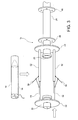
- the gun 12 comprises a barrel 24, intended to guide the smoke marker 16 in the first phase of the launch, that is, immediately after that the smoke marker 16 has left the container 14.
- the barrel 24 has an inlet 26, through which the smoke marker 16 enters the barrel immediately after leaving the container 14, and an outlet 28 through which the smoke marker 16 is projected from the barrel.
- the gun 12 further comprises a connection member 30 connected on the one hand to a compressed air supply conduit 32, in turn connected to the reservoir 20, and on the other hand to the container 14, particularly to the end of the container 14 opposite to the barrel 24.
- connection member 30 is arranged to be moved along the direction of the axis of the barrel 24 (referred to as the axial direction herein below) between a closed position, or operative position, and an open position, or non-operative position.
- the air compressor 18 is connected to the reservoir 20 by a delivery conduit 34 to store the compressed air generated at a given pressure in the reservoir 20.
- a delivery conduit 34 to store the compressed air generated at a given pressure in the reservoir 20.
- an air pressure of about 10 bars shall be provided for.
- a solenoid valve 36 provided on the delivery conduit 34 controls the compressed air flow from the air compressor 18 to the reservoir 20.
- the reservoir 20 is advantageously provided with a vent valve 38 arranged to discharge compressed air from the reservoir.
- Two further solenoid valves 40 and 42 are provided on the supply conduit 32, on the reservoir 20 side and on the connection member 30 side, respectively.
- the launch system 10 further comprises an electronic control unit 44 arranged to manage the operation of the launch system.
- the electronic control unit 44 is connected to the air compressor 18 so as to receive information from the air compressor about its operative state, and to send control signals to control the supply and cause the activation thereof. For example, the electronic control unit 44 will cause the activation of the air compressor 18 in the presence of an air pressure level signal in the reservoir 20, which is lower than a preset minimum threshold, and will cause the deactivation of the air compressor when a given air pressure level has been reached in the reservoir.
- the electronic control unit 44 is further connected to the solenoid valve 40 to receive a pressure signal indicative of the pressure in the reservoir 20 and to control the inflow of the compressed air from the reservoir 20 to the supply conduit 32 through this solenoid valve.
- the electronic control unit 44 is further connected to the vent valve 38 in order to cause the opening thereof, when needed, depending, for example, on the pressure value in the reservoir 20.
- the electronic control unit 44 is further connected to the solenoid valve 42 to control the inflow of compressed air from the supply conduit 32 to the gun 12 through this solenoid valve in order to operate the launch of the smoke marker 16.
- the electronic control unit 44 is further connected to suitable sensors provided for on the gun 12 to receive suitable release signals, for example relating to the presence of the smoke marker 16 and the proper locking of the container 14 in the gun, so as to cause the launch of the smoke marker only in the presence of such release signals.
- the barrel 24 is provided with attachment flanges 46 for securing the gun to the structure of the aircraft 100.
- the launch system is installed on the aircraft 100 with the outlet 28 of the barrel 24 facing backwards, so that the smoke marker 16 is launched in a direction opposite to the flying direction of the aircraft.
- the electronic control unit 44 is arranged to launch the smoke marker 16 with such a speed as to ensure that it will fall substantially at the interest point to be signalled. This means that, when the aircraft 100 is flying along a substantially horizontal direction, the smoke marker 16 is launched by the launch system 10 with a speed that is substantially the same as that of the aircraft.
- An additional flange 48 is further secured to the barrel 24, specifically in the end area on the side of the inlet 26.
- a similar flange 50 is secured to the connection member 30.
- Guide means are provided between the two flanges 48 and 50 and are arranged to guide the translation movement of the connection member 30 relative to the barrel 24 along the axial direction between the above-mentioned open and closed positions.
- the guide means are made as telescopic means and, in this regard, they comprise a plurality of cylinders 52 (two cylinders, in the illustrated example) secured to the flange 48, i.e.
- connection member 30 seals the container 14 against the inlet 26 of the barrel 24.
- both the connection member 30 and the inlet 26 of the barrel 24 are provided with corresponding gaskets (not shown) for a sealing coupling to the container 14.
- the connection member 30 faces away from the barrel 24 compared to the closed position, so as to allow the insertion of the container 14 into the gun 12.
- the gun 12 further comprises a manual locking mechanism comprising a plurality (advantageously, one pair, as in the illustrated example, so as to be able to be simultaneously actuated by only one operator) of dead-point levers 56 configured so that the dead-point position of such levers corresponds to the closed position of the connection member.
- the dead-point levers 56 are mounted onto the guide means 52, 54 to act on the one hand onto the connection member 30 and on the other hand onto the barrel 24. More precisely, each dead-centre lever 56 is mounted so as to act on the one hand on a respective rod 54, which is drivingly connected for axial translation to the connection member 30, and on the other hand on a respective cylinder 52, which is drivingly connected to the barrel 24.
- a dead-centre lever 56 usable in the locking mechanism of Fig. 3 is shown in Figs.
- the dead-point levers 56 are mounted onto the connection member 30 and cooperate each with a respective coupling element 58 secured to the container 14.
- An example of a dead-centre lever 56 usable in the locking mechanism of Fig. 5 is shown - in the locking position - in Fig. 6 .
- the end portion of the barrel 24 on the side of the inlet 26 has a guide slot 60 arranged to receive a guide pin 62 which is secured to the container 14 to guide the container in the loading step within the gun 12.
- the guide means arranged to guide the connection member in the axial translation movement between the open position and the closed position could be produced in a different way compared to that described and illustrated herein, as well as the locking means arranged to lock the connection member in the closed position.
- the installation position of the launch system could be different from the one shown in the figures annexed herein.
Landscapes
- Engineering & Computer Science (AREA)
- General Engineering & Computer Science (AREA)
- Aviation & Aerospace Engineering (AREA)
- Radar, Positioning & Navigation (AREA)
- Remote Sensing (AREA)
- Toys (AREA)
Claims (11)
- Aéronef (100) pourvu d'un système de lancement (10) pour lancer des balises fumigènes (16), dans lequel le système de lancement (10) est installé de manière à lancer la balise fumigène (16) dans une direction opposée à la direction de vol de l'aéronef (100), dans lequel le système de lancement (10) comprend un canon (12) et un moyen de propulsion (18, 20, 22) agencé pour générer une poussée sur la balise fumigène (16) destinée à la lancer hors du canon (12) avec une vitesse donnée, dans lequel le canon (12) comprend un tube (24) agencé pour guider la balise fumigène (16) dans la première phase du lancement, et dans lequel ledit moyen de propulsion (18, 20, 22) est un moyen de propulsion à air comprimé,
caractérisé en ce que le canon (12) est adapté pour recevoir un récipient (14) contenant la balise fumigène (16) à lancer et en ce que ledit moyen de propulsion (18, 20, 22) comprend un compresseur d'air (18) agencé pour générer de l'air comprimé à une pression donnée, un réservoir (20) pour stocker l'air comprimé généré par le compresseur d'air (18), et un moyen d'alimentation (22) agencé pour fournir de manière contrôlée au canon (12) l'air comprimé stocké dans le réservoir (20). - Aéronef selon la revendication 1, dans lequel le tube (24) du canon (12) a une entrée (26) par laquelle la balise fumigène (16) entre dans le tube (24), et une sortie (28) par laquelle la balise fumigène (16) est projetée hors du tube (24), ainsi qu'un élément de connexion (30) agencé pour être connecté d'une part à une conduite d'alimentation en air comprimé (32) faisant partie dudit moyen d'alimentation (22) et qui est lui-même connecté au réservoir (20), et d'autre part à l'extrémité du récipient (14) située à l'opposé du tube (24), et dans lequel l'élément de connexion (30) est agencé pour être déplacé le long de la direction de l'axe du tube (24) entre une position fermée, dans laquelle il relie le récipient (14) au moyen d'alimentation (22) pour permettre la distribution d'air comprimé dans le récipient (14), et une position ouverte, dans laquelle il est positionné à une plus grande distance du tube (24) que dans la position fermée afin de permettre l'insertion du récipient (14) entre l'élément de connexion (30) et le tube (24).
- Aéronef selon la revendication 2, dans lequel le canon (12) comprend en outre un moyen de verrouillage (56) agencé pour assurer le verrouillage de l'élément de connexion (30) dans la position fermée.
- Aéronef selon la revendication 3, dans lequel ledit moyen de verrouillage (56) comprend au moins un levier à point mort configuré de telle manière que la position de point mort du levier correspond à la position fermée de l'élément de connexion (30).
- Aéronef selon la revendication 3 ou 4, dans lequel ledit moyen de verrouillage (56) est agencé pour agir d'une part sur l'élément de connexion (30), ou sur un autre élément (54) connecté en entraînement pour suivre une translation axiale avec celui-ci, et d'autre part sur le tube (24), ou sur un autre élément (52) connecté en entraînement avec celui-ci.
- Aéronef selon la revendication 3 ou 4, dans lequel ledit moyen de verrouillage (56) est agencé pour agir d'une part sur l'élément de connexion (30), ou sur un autre élément connecté en entraînement pour suivre une translation axiale avec celui-ci, et d'autre part directement sur le récipient (14).
- Aéronef selon l'une quelconque des revendications 2 à 6, dans lequel le canon comprend en outre un moyen de guidage (52, 54) intercalé entre l'élément de connexion (30) et le tube (24) pour guider le mouvement de l'élément de connexion (30) entre la position ouverte et la position fermée.
- Aéronef selon la revendication 7, dans lequel ledit moyen de guidage (52, 54) se présente sous la forme d'un moyen télescopique et comprend une pluralité de cylindres (52) fixés directement ou indirectement à l'élément de connexion (30) ou au tube (24), et une pluralité correspondante de tiges (54) placées chacune de façon glissante dans un cylindre respectif (52) et fixées directement ou indirectement respectivement au tube (24) ou à l'élément de connexion (30).
- Aéronef selon l'une quelconque des revendications précédentes, dans lequel ledit moyen de propulsion (18, 20, 22) comprend en outre un premier moyen formant vanne (36) agencé pour commander le débit d'air comprimé du compresseur d'air (18) vers le réservoir (20), et un deuxième moyen formant vanne (40, 42) agencé pour commander le débit d'air comprimé du réservoir (20) vers le canon (12).
- Aéronef selon la revendication 9, comprenant en outre une unité de commande électronique (44) connectée au compresseur d'air (18) et auxdits premier et deuxième moyens formant vannes (36, 40, 42).
- Aéronef selon la revendication 10, dans lequel l'unité de commande électronique (44) est agencée pour commander le compresseur d'air (18) et lesdits premier et deuxième moyens formant vannes (36, 40, 42) de façon à lancer la balise fumigène (16), quand l'aéronef (100) vole le long d'une direction substantiellement horizontale, avec une vitesse égale à celle de l'aéronef (100).
Applications Claiming Priority (1)
| Application Number | Priority Date | Filing Date | Title |
|---|---|---|---|
| IT000398A ITTO20110398A1 (it) | 2011-05-05 | 2011-05-05 | Velivolo provvisto di sistema per il lancio di razzi fumogeni |
Publications (2)
| Publication Number | Publication Date |
|---|---|
| EP2520897A1 EP2520897A1 (fr) | 2012-11-07 |
| EP2520897B1 true EP2520897B1 (fr) | 2014-07-09 |
Family
ID=44899128
Family Applications (1)
| Application Number | Title | Priority Date | Filing Date |
|---|---|---|---|
| EP20120166744 Active EP2520897B1 (fr) | 2011-05-05 | 2012-05-04 | Aéronef pourvu d'un système de lancement pour le lancement de bougies fumigènes |
Country Status (3)
| Country | Link |
|---|---|
| EP (1) | EP2520897B1 (fr) |
| ES (1) | ES2509962T3 (fr) |
| IT (1) | ITTO20110398A1 (fr) |
Cited By (1)
| Publication number | Priority date | Publication date | Assignee | Title |
|---|---|---|---|---|
| CN106871740A (zh) * | 2017-03-30 | 2017-06-20 | 西安天鹰防务科技有限公司 | 炮筒组件、炮弹挂载架及炮弹挂载架在无人机上的应用 |
Family Cites Families (6)
| Publication number | Priority date | Publication date | Assignee | Title |
|---|---|---|---|---|
| FR931787A (fr) * | 1946-08-06 | 1948-03-03 | Arme portative actionnée au moyen de l'air comprimé | |
| DE977805C (de) * | 1967-02-27 | 1970-07-30 | Messerschmitt Boelkow Blohm | Einrichtung zum Abwerfen von Schuettgut aus an Flugzeugen befestigten Behaeltern |
| DE2627183C2 (de) * | 1976-06-18 | 1987-05-07 | Messerschmitt-Bölkow-Blohm GmbH, 8012 Ottobrunn | Einrichtung zur Bekämpfung von Bodenzielen an einem fliegenden Waffenträger |
| US5333528A (en) * | 1992-08-28 | 1994-08-02 | Hughes Aircraft Company | Multiple missile ejection system |
| US20030121404A1 (en) * | 2000-05-08 | 2003-07-03 | O'dwyer James Michael | Attack aircraft |
| DE102009020558A1 (de) * | 2009-05-08 | 2010-11-18 | Rheinmetall Waffe Munition Gmbh | Aktivierungseinheit für munitionsfreie Scheinziele |
-
2011
- 2011-05-05 IT IT000398A patent/ITTO20110398A1/it unknown
-
2012
- 2012-05-04 ES ES12166744.8T patent/ES2509962T3/es active Active
- 2012-05-04 EP EP20120166744 patent/EP2520897B1/fr active Active
Cited By (1)
| Publication number | Priority date | Publication date | Assignee | Title |
|---|---|---|---|---|
| CN106871740A (zh) * | 2017-03-30 | 2017-06-20 | 西安天鹰防务科技有限公司 | 炮筒组件、炮弹挂载架及炮弹挂载架在无人机上的应用 |
Also Published As
| Publication number | Publication date |
|---|---|
| ES2509962T3 (es) | 2014-10-20 |
| ITTO20110398A1 (it) | 2012-11-06 |
| EP2520897A1 (fr) | 2012-11-07 |
Similar Documents
| Publication | Publication Date | Title |
|---|---|---|
| US4951644A (en) | Pneumatic launcher | |
| US9783296B2 (en) | Aircraft store deployment system with improved safety of arming and releasing stores | |
| KR101923577B1 (ko) | 수중 이동체 발사 시스템 | |
| US10030943B2 (en) | Air cannon and associated launch canister for a line-fouling system | |
| EP2421754B1 (fr) | Unité de distribution avec compartiments fermables de contre-mésure | |
| US7921839B2 (en) | Air release and bolt design for a paintball marker | |
| US10597170B2 (en) | Arrangement in catapult | |
| EP0955236B1 (fr) | Rampe d'éjection avec un seul crochet pour munitions miniatures | |
| US5907118A (en) | Stores ejection system | |
| US8104463B2 (en) | Bolt and valve mechanism that uses less gas | |
| US20070069071A1 (en) | Systems and methods for providing back-up hydraulic power for aircraft, including tanker aircraft | |
| US10472076B2 (en) | Release system for evacuation slide assembly | |
| EP2520897B1 (fr) | Aéronef pourvu d'un système de lancement pour le lancement de bougies fumigènes | |
| US8127655B1 (en) | Low force bomb rack release mechanism | |
| US12123678B2 (en) | Projectile launcher | |
| US8127656B1 (en) | General purpose pneumatic power module | |
| KR100380946B1 (ko) | 광어뢰 형태의 무기를 저장하고 발사하기 위한 콘테이너 | |
| IL323035A (en) | Anti-CD25 antigen-binding proteins and their uses | |
| US10538330B2 (en) | Store ejection system and method of discharging a store from a vehicle | |
| EP1894834B1 (fr) | Flotteur pour un dispositif lancé dans la mer par route aérienne, en particulier pour un dispositif de contre-mesure | |
| US20120192846A1 (en) | Paintball marker | |
| US3093034A (en) | Pneumatic jettisoning device | |
| US20050151020A1 (en) | Pneumatic conversion system | |
| DE10356157B4 (de) | Verfahren und Vorrichtungen für den Marschflugkörper-Verschuß mittels Booster-Plattform | |
| US20070181030A1 (en) | Accident prevent launcher |
Legal Events
| Date | Code | Title | Description |
|---|---|---|---|
| PUAI | Public reference made under article 153(3) epc to a published international application that has entered the european phase |
Free format text: ORIGINAL CODE: 0009012 |
|
| AK | Designated contracting states |
Kind code of ref document: A1 Designated state(s): AL AT BE BG CH CY CZ DE DK EE ES FI FR GB GR HR HU IE IS IT LI LT LU LV MC MK MT NL NO PL PT RO RS SE SI SK SM TR |
|
| AX | Request for extension of the european patent |
Extension state: BA ME |
|
| 17P | Request for examination filed |
Effective date: 20130402 |
|
| RIC1 | Information provided on ipc code assigned before grant |
Ipc: B64D 7/00 20060101ALN20131125BHEP Ipc: F41B 11/681 20130101ALI20131125BHEP Ipc: F42B 5/155 20060101AFI20131125BHEP Ipc: B64D 1/02 20060101ALI20131125BHEP |
|
| GRAP | Despatch of communication of intention to grant a patent |
Free format text: ORIGINAL CODE: EPIDOSNIGR1 |
|
| INTG | Intention to grant announced |
Effective date: 20140110 |
|
| GRAS | Grant fee paid |
Free format text: ORIGINAL CODE: EPIDOSNIGR3 |
|
| GRAA | (expected) grant |
Free format text: ORIGINAL CODE: 0009210 |
|
| AK | Designated contracting states |
Kind code of ref document: B1 Designated state(s): AL AT BE BG CH CY CZ DE DK EE ES FI FR GB GR HR HU IE IS IT LI LT LU LV MC MK MT NL NO PL PT RO RS SE SI SK SM TR |
|
| REG | Reference to a national code |
Ref country code: GB Ref legal event code: FG4D |
|
| REG | Reference to a national code |
Ref country code: AT Ref legal event code: REF Ref document number: 676728 Country of ref document: AT Kind code of ref document: T Effective date: 20140715 Ref country code: CH Ref legal event code: EP |
|
| REG | Reference to a national code |
Ref country code: IE Ref legal event code: FG4D |
|
| REG | Reference to a national code |
Ref country code: DE Ref legal event code: R096 Ref document number: 602012002333 Country of ref document: DE Effective date: 20140821 |
|
| REG | Reference to a national code |
Ref country code: ES Ref legal event code: FG2A Ref document number: 2509962 Country of ref document: ES Kind code of ref document: T3 Effective date: 20141020 |
|
| RAP2 | Party data changed (patent owner data changed or rights of a patent transferred) |
Owner name: ALENIA AERMACCHI S.P.A. |
|
| REG | Reference to a national code |
Ref country code: AT Ref legal event code: MK05 Ref document number: 676728 Country of ref document: AT Kind code of ref document: T Effective date: 20140709 |
|
| REG | Reference to a national code |
Ref country code: NL Ref legal event code: VDEP Effective date: 20140709 |
|
| REG | Reference to a national code |
Ref country code: LT Ref legal event code: MG4D |
|
| PG25 | Lapsed in a contracting state [announced via postgrant information from national office to epo] |
Ref country code: NO Free format text: LAPSE BECAUSE OF FAILURE TO SUBMIT A TRANSLATION OF THE DESCRIPTION OR TO PAY THE FEE WITHIN THE PRESCRIBED TIME-LIMIT Effective date: 20141009 Ref country code: GR Free format text: LAPSE BECAUSE OF FAILURE TO SUBMIT A TRANSLATION OF THE DESCRIPTION OR TO PAY THE FEE WITHIN THE PRESCRIBED TIME-LIMIT Effective date: 20141010 Ref country code: BG Free format text: LAPSE BECAUSE OF FAILURE TO SUBMIT A TRANSLATION OF THE DESCRIPTION OR TO PAY THE FEE WITHIN THE PRESCRIBED TIME-LIMIT Effective date: 20141009 Ref country code: LT Free format text: LAPSE BECAUSE OF FAILURE TO SUBMIT A TRANSLATION OF THE DESCRIPTION OR TO PAY THE FEE WITHIN THE PRESCRIBED TIME-LIMIT Effective date: 20140709 Ref country code: SE Free format text: LAPSE BECAUSE OF FAILURE TO SUBMIT A TRANSLATION OF THE DESCRIPTION OR TO PAY THE FEE WITHIN THE PRESCRIBED TIME-LIMIT Effective date: 20140709 Ref country code: PT Free format text: LAPSE BECAUSE OF FAILURE TO SUBMIT A TRANSLATION OF THE DESCRIPTION OR TO PAY THE FEE WITHIN THE PRESCRIBED TIME-LIMIT Effective date: 20141110 Ref country code: FI Free format text: LAPSE BECAUSE OF FAILURE TO SUBMIT A TRANSLATION OF THE DESCRIPTION OR TO PAY THE FEE WITHIN THE PRESCRIBED TIME-LIMIT Effective date: 20140709 |
|
| PG25 | Lapsed in a contracting state [announced via postgrant information from national office to epo] |
Ref country code: RS Free format text: LAPSE BECAUSE OF FAILURE TO SUBMIT A TRANSLATION OF THE DESCRIPTION OR TO PAY THE FEE WITHIN THE PRESCRIBED TIME-LIMIT Effective date: 20140709 Ref country code: CY Free format text: LAPSE BECAUSE OF FAILURE TO SUBMIT A TRANSLATION OF THE DESCRIPTION OR TO PAY THE FEE WITHIN THE PRESCRIBED TIME-LIMIT Effective date: 20140709 Ref country code: NL Free format text: LAPSE BECAUSE OF FAILURE TO SUBMIT A TRANSLATION OF THE DESCRIPTION OR TO PAY THE FEE WITHIN THE PRESCRIBED TIME-LIMIT Effective date: 20140709 Ref country code: LV Free format text: LAPSE BECAUSE OF FAILURE TO SUBMIT A TRANSLATION OF THE DESCRIPTION OR TO PAY THE FEE WITHIN THE PRESCRIBED TIME-LIMIT Effective date: 20140709 Ref country code: AT Free format text: LAPSE BECAUSE OF FAILURE TO SUBMIT A TRANSLATION OF THE DESCRIPTION OR TO PAY THE FEE WITHIN THE PRESCRIBED TIME-LIMIT Effective date: 20140709 Ref country code: PL Free format text: LAPSE BECAUSE OF FAILURE TO SUBMIT A TRANSLATION OF THE DESCRIPTION OR TO PAY THE FEE WITHIN THE PRESCRIBED TIME-LIMIT Effective date: 20140709 Ref country code: HR Free format text: LAPSE BECAUSE OF FAILURE TO SUBMIT A TRANSLATION OF THE DESCRIPTION OR TO PAY THE FEE WITHIN THE PRESCRIBED TIME-LIMIT Effective date: 20140709 Ref country code: IS Free format text: LAPSE BECAUSE OF FAILURE TO SUBMIT A TRANSLATION OF THE DESCRIPTION OR TO PAY THE FEE WITHIN THE PRESCRIBED TIME-LIMIT Effective date: 20141109 |
|
| REG | Reference to a national code |
Ref country code: DE Ref legal event code: R097 Ref document number: 602012002333 Country of ref document: DE |
|
| PG25 | Lapsed in a contracting state [announced via postgrant information from national office to epo] |
Ref country code: DK Free format text: LAPSE BECAUSE OF FAILURE TO SUBMIT A TRANSLATION OF THE DESCRIPTION OR TO PAY THE FEE WITHIN THE PRESCRIBED TIME-LIMIT Effective date: 20140709 Ref country code: EE Free format text: LAPSE BECAUSE OF FAILURE TO SUBMIT A TRANSLATION OF THE DESCRIPTION OR TO PAY THE FEE WITHIN THE PRESCRIBED TIME-LIMIT Effective date: 20140709 Ref country code: SK Free format text: LAPSE BECAUSE OF FAILURE TO SUBMIT A TRANSLATION OF THE DESCRIPTION OR TO PAY THE FEE WITHIN THE PRESCRIBED TIME-LIMIT Effective date: 20140709 Ref country code: CZ Free format text: LAPSE BECAUSE OF FAILURE TO SUBMIT A TRANSLATION OF THE DESCRIPTION OR TO PAY THE FEE WITHIN THE PRESCRIBED TIME-LIMIT Effective date: 20140709 |
|
| PLBE | No opposition filed within time limit |
Free format text: ORIGINAL CODE: 0009261 |
|
| STAA | Information on the status of an ep patent application or granted ep patent |
Free format text: STATUS: NO OPPOSITION FILED WITHIN TIME LIMIT |
|
| 26N | No opposition filed |
Effective date: 20150410 |
|
| PG25 | Lapsed in a contracting state [announced via postgrant information from national office to epo] |
Ref country code: SI Free format text: LAPSE BECAUSE OF FAILURE TO SUBMIT A TRANSLATION OF THE DESCRIPTION OR TO PAY THE FEE WITHIN THE PRESCRIBED TIME-LIMIT Effective date: 20140709 |
|
| REG | Reference to a national code |
Ref country code: CH Ref legal event code: PL |
|
| PG25 | Lapsed in a contracting state [announced via postgrant information from national office to epo] |
Ref country code: CH Free format text: LAPSE BECAUSE OF NON-PAYMENT OF DUE FEES Effective date: 20150531 Ref country code: LI Free format text: LAPSE BECAUSE OF NON-PAYMENT OF DUE FEES Effective date: 20150531 Ref country code: LU Free format text: LAPSE BECAUSE OF FAILURE TO SUBMIT A TRANSLATION OF THE DESCRIPTION OR TO PAY THE FEE WITHIN THE PRESCRIBED TIME-LIMIT Effective date: 20150504 Ref country code: MC Free format text: LAPSE BECAUSE OF FAILURE TO SUBMIT A TRANSLATION OF THE DESCRIPTION OR TO PAY THE FEE WITHIN THE PRESCRIBED TIME-LIMIT Effective date: 20140709 |
|
| REG | Reference to a national code |
Ref country code: IE Ref legal event code: MM4A |
|
| PG25 | Lapsed in a contracting state [announced via postgrant information from national office to epo] |
Ref country code: IE Free format text: LAPSE BECAUSE OF NON-PAYMENT OF DUE FEES Effective date: 20150504 |
|
| REG | Reference to a national code |
Ref country code: FR Ref legal event code: PLFP Year of fee payment: 5 |
|
| PG25 | Lapsed in a contracting state [announced via postgrant information from national office to epo] |
Ref country code: BE Free format text: LAPSE BECAUSE OF FAILURE TO SUBMIT A TRANSLATION OF THE DESCRIPTION OR TO PAY THE FEE WITHIN THE PRESCRIBED TIME-LIMIT Effective date: 20140709 |
|
| PG25 | Lapsed in a contracting state [announced via postgrant information from national office to epo] |
Ref country code: MT Free format text: LAPSE BECAUSE OF FAILURE TO SUBMIT A TRANSLATION OF THE DESCRIPTION OR TO PAY THE FEE WITHIN THE PRESCRIBED TIME-LIMIT Effective date: 20140709 |
|
| REG | Reference to a national code |
Ref country code: FR Ref legal event code: PLFP Year of fee payment: 6 |
|
| PG25 | Lapsed in a contracting state [announced via postgrant information from national office to epo] |
Ref country code: SM Free format text: LAPSE BECAUSE OF FAILURE TO SUBMIT A TRANSLATION OF THE DESCRIPTION OR TO PAY THE FEE WITHIN THE PRESCRIBED TIME-LIMIT Effective date: 20140709 Ref country code: HU Free format text: LAPSE BECAUSE OF FAILURE TO SUBMIT A TRANSLATION OF THE DESCRIPTION OR TO PAY THE FEE WITHIN THE PRESCRIBED TIME-LIMIT; INVALID AB INITIO Effective date: 20120504 Ref country code: RO Free format text: LAPSE BECAUSE OF FAILURE TO SUBMIT A TRANSLATION OF THE DESCRIPTION OR TO PAY THE FEE WITHIN THE PRESCRIBED TIME-LIMIT Effective date: 20140709 |
|
| PG25 | Lapsed in a contracting state [announced via postgrant information from national office to epo] |
Ref country code: TR Free format text: LAPSE BECAUSE OF FAILURE TO SUBMIT A TRANSLATION OF THE DESCRIPTION OR TO PAY THE FEE WITHIN THE PRESCRIBED TIME-LIMIT Effective date: 20140709 |
|
| REG | Reference to a national code |
Ref country code: FR Ref legal event code: PLFP Year of fee payment: 7 |
|
| PG25 | Lapsed in a contracting state [announced via postgrant information from national office to epo] |
Ref country code: MK Free format text: LAPSE BECAUSE OF FAILURE TO SUBMIT A TRANSLATION OF THE DESCRIPTION OR TO PAY THE FEE WITHIN THE PRESCRIBED TIME-LIMIT Effective date: 20140709 |
|
| PG25 | Lapsed in a contracting state [announced via postgrant information from national office to epo] |
Ref country code: AL Free format text: LAPSE BECAUSE OF FAILURE TO SUBMIT A TRANSLATION OF THE DESCRIPTION OR TO PAY THE FEE WITHIN THE PRESCRIBED TIME-LIMIT Effective date: 20140709 |
|
| PGFP | Annual fee paid to national office [announced via postgrant information from national office to epo] |
Ref country code: GB Payment date: 20190521 Year of fee payment: 8 |
|
| GBPC | Gb: european patent ceased through non-payment of renewal fee |
Effective date: 20200504 |
|
| PG25 | Lapsed in a contracting state [announced via postgrant information from national office to epo] |
Ref country code: GB Free format text: LAPSE BECAUSE OF NON-PAYMENT OF DUE FEES Effective date: 20200504 |
|
| REG | Reference to a national code |
Ref country code: ES Ref legal event code: FD2A Effective date: 20210927 |
|
| PG25 | Lapsed in a contracting state [announced via postgrant information from national office to epo] |
Ref country code: ES Free format text: LAPSE BECAUSE OF NON-PAYMENT OF DUE FEES Effective date: 20200505 |
|
| PGFP | Annual fee paid to national office [announced via postgrant information from national office to epo] |
Ref country code: IT Payment date: 20250306 Year of fee payment: 14 |
|
| PGFP | Annual fee paid to national office [announced via postgrant information from national office to epo] |
Ref country code: DE Payment date: 20250523 Year of fee payment: 14 |
|
| PGFP | Annual fee paid to national office [announced via postgrant information from national office to epo] |
Ref country code: FR Payment date: 20250430 Year of fee payment: 14 |