EP2520909A1 - Système et procédé d'inspection de réservoir de stockage - Google Patents
Système et procédé d'inspection de réservoir de stockage Download PDFInfo
- Publication number
- EP2520909A1 EP2520909A1 EP12164667A EP12164667A EP2520909A1 EP 2520909 A1 EP2520909 A1 EP 2520909A1 EP 12164667 A EP12164667 A EP 12164667A EP 12164667 A EP12164667 A EP 12164667A EP 2520909 A1 EP2520909 A1 EP 2520909A1
- Authority
- EP
- European Patent Office
- Prior art keywords
- storage tank
- infrared
- image
- tank
- sensor
- Prior art date
- Legal status (The legal status is an assumption and is not a legal conclusion. Google has not performed a legal analysis and makes no representation as to the accuracy of the status listed.)
- Withdrawn
Links
Images


Classifications
-
- G—PHYSICS
- G01—MEASURING; TESTING
- G01F—MEASURING VOLUME, VOLUME FLOW, MASS FLOW OR LIQUID LEVEL; METERING BY VOLUME
- G01F23/00—Indicating or measuring liquid level or level of fluent solid material, e.g. indicating in terms of volume or indicating by means of an alarm
- G01F23/22—Indicating or measuring liquid level or level of fluent solid material, e.g. indicating in terms of volume or indicating by means of an alarm by measuring physical variables, other than linear dimensions, pressure or weight, dependent on the level to be measured, e.g. by difference of heat transfer of steam or water
- G01F23/28—Indicating or measuring liquid level or level of fluent solid material, e.g. indicating in terms of volume or indicating by means of an alarm by measuring physical variables, other than linear dimensions, pressure or weight, dependent on the level to be measured, e.g. by difference of heat transfer of steam or water by measuring the variations of parameters of electromagnetic or acoustic waves applied directly to the liquid or fluent solid material
- G01F23/284—Electromagnetic waves
- G01F23/292—Light, e.g. infrared or ultraviolet
-
- G—PHYSICS
- G01—MEASURING; TESTING
- G01F—MEASURING VOLUME, VOLUME FLOW, MASS FLOW OR LIQUID LEVEL; METERING BY VOLUME
- G01F23/00—Indicating or measuring liquid level or level of fluent solid material, e.g. indicating in terms of volume or indicating by means of an alarm
- G01F23/22—Indicating or measuring liquid level or level of fluent solid material, e.g. indicating in terms of volume or indicating by means of an alarm by measuring physical variables, other than linear dimensions, pressure or weight, dependent on the level to be measured, e.g. by difference of heat transfer of steam or water
-
- G—PHYSICS
- G01—MEASURING; TESTING
- G01F—MEASURING VOLUME, VOLUME FLOW, MASS FLOW OR LIQUID LEVEL; METERING BY VOLUME
- G01F23/00—Indicating or measuring liquid level or level of fluent solid material, e.g. indicating in terms of volume or indicating by means of an alarm
- G01F23/22—Indicating or measuring liquid level or level of fluent solid material, e.g. indicating in terms of volume or indicating by means of an alarm by measuring physical variables, other than linear dimensions, pressure or weight, dependent on the level to be measured, e.g. by difference of heat transfer of steam or water
- G01F23/28—Indicating or measuring liquid level or level of fluent solid material, e.g. indicating in terms of volume or indicating by means of an alarm by measuring physical variables, other than linear dimensions, pressure or weight, dependent on the level to be measured, e.g. by difference of heat transfer of steam or water by measuring the variations of parameters of electromagnetic or acoustic waves applied directly to the liquid or fluent solid material
- G01F23/284—Electromagnetic waves
-
- G—PHYSICS
- G01—MEASURING; TESTING
- G01F—MEASURING VOLUME, VOLUME FLOW, MASS FLOW OR LIQUID LEVEL; METERING BY VOLUME
- G01F23/00—Indicating or measuring liquid level or level of fluent solid material, e.g. indicating in terms of volume or indicating by means of an alarm
- G01F23/22—Indicating or measuring liquid level or level of fluent solid material, e.g. indicating in terms of volume or indicating by means of an alarm by measuring physical variables, other than linear dimensions, pressure or weight, dependent on the level to be measured, e.g. by difference of heat transfer of steam or water
- G01F23/28—Indicating or measuring liquid level or level of fluent solid material, e.g. indicating in terms of volume or indicating by means of an alarm by measuring physical variables, other than linear dimensions, pressure or weight, dependent on the level to be measured, e.g. by difference of heat transfer of steam or water by measuring the variations of parameters of electromagnetic or acoustic waves applied directly to the liquid or fluent solid material
- G01F23/296—Acoustic waves
- G01F23/2962—Measuring transit time of reflected waves
-
- G—PHYSICS
- G01—MEASURING; TESTING
- G01S—RADIO DIRECTION-FINDING; RADIO NAVIGATION; DETERMINING DISTANCE OR VELOCITY BY USE OF RADIO WAVES; LOCATING OR PRESENCE-DETECTING BY USE OF THE REFLECTION OR RERADIATION OF RADIO WAVES; ANALOGOUS ARRANGEMENTS USING OTHER WAVES
- G01S13/00—Systems using the reflection or reradiation of radio waves, e.g. radar systems; Analogous systems using reflection or reradiation of waves whose nature or wavelength is irrelevant or unspecified
- G01S13/86—Combinations of radar systems with non-radar systems, e.g. sonar, direction finder
- G01S13/862—Combination of radar systems with sonar systems
-
- G—PHYSICS
- G01—MEASURING; TESTING
- G01S—RADIO DIRECTION-FINDING; RADIO NAVIGATION; DETERMINING DISTANCE OR VELOCITY BY USE OF RADIO WAVES; LOCATING OR PRESENCE-DETECTING BY USE OF THE REFLECTION OR RERADIATION OF RADIO WAVES; ANALOGOUS ARRANGEMENTS USING OTHER WAVES
- G01S13/00—Systems using the reflection or reradiation of radio waves, e.g. radar systems; Analogous systems using reflection or reradiation of waves whose nature or wavelength is irrelevant or unspecified
- G01S13/88—Radar or analogous systems specially adapted for specific applications
-
- G—PHYSICS
- G01—MEASURING; TESTING
- G01S—RADIO DIRECTION-FINDING; RADIO NAVIGATION; DETERMINING DISTANCE OR VELOCITY BY USE OF RADIO WAVES; LOCATING OR PRESENCE-DETECTING BY USE OF THE REFLECTION OR RERADIATION OF RADIO WAVES; ANALOGOUS ARRANGEMENTS USING OTHER WAVES
- G01S15/00—Systems using the reflection or reradiation of acoustic waves, e.g. sonar systems
- G01S15/88—Sonar systems specially adapted for specific applications
-
- G—PHYSICS
- G01—MEASURING; TESTING
- G01F—MEASURING VOLUME, VOLUME FLOW, MASS FLOW OR LIQUID LEVEL; METERING BY VOLUME
- G01F22/00—Methods or apparatus for measuring volume of fluids or fluent solid material, not otherwise provided for
Definitions
- Disclosed embodiments relate to the field of inspection of storage tanks that hold liquids, and more particularly to the automatic inspection of such storage tanks.
- sludge Another problem associated with the manual inspection of conventional large storage tanks involves the presence of multiple layers formed within the tank due to various compositions.
- multiple layers such as crude, paraffin, water and sediment (technically collectively referred to as "sludge")
- sludge due to its higher density compared to the petroleum product stored, may form at the bottom of the tank, or stick to the sides of the tank, due to prolonged storage.
- the sludge layer may be anywhere from several millimeters to one meter or more thick.
- One of the goals of a proper inspection is to estimate the sludge level in a storage tank, as well as other layer levels, as accurately as possible, in order to proceed with cleaning if required. It can be difficult for human inspectors, however, to measure the sludge level underneath other layers of liquid, nor is it easy for them to manually measure tens of sampling points on top of the tank. Another concern is integrity of the shell of the tanks, which can degrade due to aging, earthquakes, or bad weather impacts, etc., which generally requires accurate inspection with a traditional visual method applied to an emptied storage tank.
- Disclosed embodiments include a multi-sensor method for inspecting storage tanks that hold a liquid. Although each sensor has its own particular limitations when working in isolation, as disclosed herein, data from multiple sensors is combined in a way that complement each other to provide a reliable and accurate solution for the inspection of storage tanks that hold liquids.
- the method includes generating an infrared (IR) image and an ultrasonic image of the exterior of the storage tank, and generating at least one of an ultrasonic (ultrasound) image and a radar image of the interior of the storage tank.
- the method further includes fusing the respective images, to generate a sludge level in the storage tank, a liquid level in the storage tank, and optionally an integrity profile of a shell of the storage tank.
- the imaging system comprises an IR sensor including a scanning vertical mount positioned outside the storage tank, an ultrasonic sensor positioned outside the storage tank, and at least one of an ultrasonic sensor positioned inside the storage tank and a phased array radar positioned inside the storage tank secured to the interior top surface of the storage tank.
- the imaging system further includes a processor coupled to receive multi-sensor data from the respective sensors.
- the processor fuses (i.e. combines) the multi-sensor data to generate a sludge level in the storage tank, a liquid level in the storage tank, and optionally an integrity profile for a shell of the storage tank.
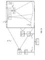
- FIG. 1A is an example illustration of a multi-sensor tank imaging system shown in conjunction with a large storage tank, according to an example embodiment.
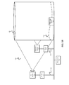
- FIG. 1B is an example illustration of another multi-sensor tank imaging system shown in conjunction with a large storage tank, according to an example embodiment.
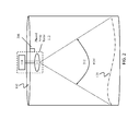
- FIG. 2 is an example illustration of a phased-array radar system shown in conjunction with a large storage tank, according to an example embodiment.
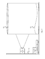
- FIG. 3 is an example illustration of an IR camera system shown in conjunction with a large storage tank, according to an example embodiment.
- FIG. 4 is an example illustration of an IR camera system shown in conjunction with a large storage tank, according to an example embodiment.
- FIG. 5 is an example illustration of an IR camera system shown in conjunction with a large storage tank, according to an example embodiment.
- FIG. 6 is an example illustration of an IR camera system shown in conjunction with a large storage tank, according to an example embodiment.
- FIG. 7 is an example illustration of an IR camera system shown in conjunction with a large storage tank, according to an example embodiment.
- FIG. 1A is an example illustration of a multi-sensor imaging system 100 shown in conjunction with a large storage tank 102, according to an example embodiment.
- the imaging system 100 includes an IR sensor (also referred to as IR camera) 104 including a scanning vertical mount 106 positioned outside the storage tank 102, an ultrasonic sensor 110 (generally an ultrasonic sensor array, and referred to herein as ultrasonic sensor array 110) positioned outside the storage tank on a scanning vertical mount 116, an ultrasonic sensor 108 positioned inside the storage tank and optionally secured to an interior top surface of the storage tank 102, and a phased array radar system 112 positioned inside the storage tank 102 secured to the interior top surface of the storage tank.
- the scanning vertical mounts 106 and 116 each include a motor 119 for moving their respective sensors in the vertical direction.
- a controller (not shown) is generally provided for controlling the motor 119 to control the vertical position of the IR sensor
- the phased array radar system 112 includes an antenna array 113, where the radiating elements of the antenna array 113 are connected to electronics and processing unit comprising high-resolution RF transmitter-receiver modules 118.
- the wide field of view (FOV) shown provided by phased array radar system 112 in FIG. 1A is generally implemented by a narrow beam from antenna array 113 that is electronically beam scanned by electronics in the electronics and processing unit comprising high-resolution RF transmitter-receiver modules 118.
- the imaging system 100 further includes a processor 114 coupled to receive multi-sensor data from sensors including the IR sensor 104, the ultrasonic sensor 108, ultrasonic sensor array 110, and phased array radar 112.
- the method can include fusing together an IR image from the IR sensor 104, ultrasonic images from the ultrasonic sensors 108 and 110, and a radar image from the phased array radar 112 to generate a sludge level 120 in the storage tank 102, a liquid level in the storage tank, and optionally an integrity profile of the shell of the storage tank 102.
- Data fusion of the data from the respective sensors can be realized by converting the respective sensor measurements into a common coordinate system, since each of the sensors is placed at a different location, and therefore the reference axis varies among each sensor. Measurements taken from individual sensors can be mapped to a common reference system. Positioning data, such from as global positioning system (GPS) associated with the sensors helps to map the measurements from each of them onto one common coordinate system.
- GPS global positioning system
- cross-sensor calibration which refers to calibration between heterogeneous (i.e., different) sensors, can be used to convert the measurements from the different sensors into the common coordinate system.
- cross-sensor calibration including both an IR sensor 104 and an ultrasound sensor array 110 on the outside of the tank 102 mounted on the same vertical mount can ease the data fusion processing.
- non-uniform interpolation (or non-linear interpolation since the profiling is dealing with rough surface fluctuation) can be performed to populate the missing measurements from the various sensors to produce a continuous 3D sludge profile. Since the measurements from the different sensors are distributed randomly inside the tank, to obtain a continuous 3D (complete 360°) profile, the missing measurement points needs to be filled. The operation to fill missing measurements from available measurements is referred to as non-uniform interpolation (or non-linear interpolation since the profiling is dealing with rough surface fluctuation) to populate the missing measurements inside the tank.
- This data fusion process can provide a complete 360° sludge profile 120 inside the tank 102.
- the sludge profile 120 may be visualized with an interactive visualization tool provided on a computer, through which a tank operator can view the complete sludge profile by panning and zooming the tank image displayed on a suitable display device.
- the phased array radar 112 for multi-sensor imaging system 100 can comprise a high-resolution phased-array imaging radar for imaging the liquid (e.g., oil) surface and sludge surface 120 within the storage tank 102.
- Conventional high-resolution imaging radars are known as radio detection and ranging instruments that are used in level measurements in tanks.
- Existing radar based gauging solutions are limited to measure a single liquid level, which is a single point measurement.
- the disclosed use of phased array radar facilitates measuring non-uniform profiles of sludge, which requires multi-point measurements.
- the phase and power of the radar signal can be varied to accommodate different dielectric media.
- conventional radar level gauges cannot be used for imaging inside a large storage tank because they are developed for distance measurements, because they have large beam widths covering a wide footprint on the surface of liquid inside the tank, and because their antennas must be sealed to the nozzle on the storage tank to prevent leakage (e.g., petrochemical gas leakage) from exiting the tank. Further, moving parts on the antenna and radar body inhibit its use in storage tanks. Therefore, imaging the contents of a tank with conventional radar gauging technology is not generally possible.
- phased array radar 112 that can be a miniaturized high-resolution phased-array radar, which has a narrow beam-width, a smaller footprint, broad bandwidth, and electronically-controlled beam scanning over the surface of the liquid and/or sludge on the tank bottom.
- FIG. 2 shows one example embodiment showing phased-array radar system 112 embodied as electronics and processing unit comprising high-resolution RF transmitter-receiver modules 118 connected to digitally controlled phased antenna array 113 comprising a plurality of antenna elements both located within the storage tank 102.
- Phased-array radar 112 has the ability to avoid obstacles in the tank 102, and can penetrate through the layers (e.g., oil layers) of liquid in the tank 102 to image the tank bottom with resolution in both planes to provide 3 dimensional (3D) data.
- the method can provide not only imaging results of the sludge profile 120 in 3D, but also provide more information about the surface of the liquid in 3D, and can be especially useful to monitor non-planar surfaces, and/or a non-horizontal roof or top of the tank 102.
- the phased-array radar 112 is mounted at a fixed mechanical structure 208 inside the tank, shown at the top of the tank 102.
- the electronics and processing unit comprising high-resolution RF transmitter-receiver modules 118 associated with the phased array radar 112 are generally located outside the tank 102 as shown in FIG. 2 .
- the beam scanning of the antenna array 113 is generally controlled electronically to cover different areas of the surface of the tank 102 product with a small footprint. Transmission of the data processed by the phased-array radar 112 to the processor 114 (e.g., a central processing unit) shown in FIG. 1A can be through a wireless mode or wired mode.
- the beamforming of the phased-array radar 112 can be performed either by software, hardware or any combination of the two. Since the antenna array 113 is sealed and generally fixed to the tank nozzle, the radar beam is electronically steered with an angle 212 to cover the area of the tank content.
- the phased-array radar 112 cannot only provide the surface profile of the tank bottom, and sludge, but it can also provide accurate intermediate liquid-level data, which are currently measured by level gauges.
- the phased-array radar 112 can be used as a level gauging radar when liquid movement takes place, in addition to being used as an imaging radar to detect the sludge and any defects in the bottom of the tank 102.
- Multi-sensor imaging system 100 shown in FIG. 1A comprises an ultrasonic sensor array 110 that is positioned along the exterior of the tank 102, and an ultrasonic sensor 108 that is positioned within the interior of the tank 102.
- Ultrasonic sensor 108 can be an ultrasonic sensor or ultrasonic sensor array.
- the ultrasonic sensor 108 within the tank can be secured to an interior top surface or the bottom of the storage tank 102.
- An ultrasonic sensor array 110 installed outside the tank 102 can be used to detect the cracks of the tank shell using acoustic emission principles.
- Ultrasonic sensors 108 located at the top of the tank 102 are particularly useful for situations such as when the level of the liquid remains high and the phased array radar 112 cannot penetrate through the liquid to reach the sludge layer 120.
- Ultrasound technology can be used for calculating the sludge level 120 in a tank 102.
- the acoustic frequency waves transmitted by the ultrasonic sensor into a tank farm provides different responses for different liquid levels, since sound waves travel at different velocities in different mediums and the reflected signal varies for sludge and other liquids.
- Ultrasonic waves can further penetrate through metallic material such as the tank wall and tank bottom. Consequently, ultrasound technology can also detect defects/cracks of the tank shell, which aids in preventing potentially large losses caused by leakages.
- Ultrasound technology further includes 3D ultrasonic sensing that formats sound wave data into 3D images. Moreover, four-dimensional (4D) ultrasound is 3D ultrasound in motion.
- Obtaining a sludge profile on one side of a liquid storage tank is generally not helpful, due to the large circumference of the tank.
- obtaining the sludge profile on all sides of the tank is generally desirable. This can be provided by placing more than one sensor around exterior of the tank 102 such that the sensors cover the complete circumference of the tank. Once data from all sensors is obtained, the data can be used to generate a 2D profile.
- 3D data can be used by adding data for a third dimension as described below, or be synthetically generated to provide a quasi-3D profile by non-linear interpolation as described above.
- the top profile of the sludge within the tank 102 can be obtained, such as by an array of sensors placed on the tank that transmit narrow-beam signals, and the reflected signals are captured and used to calculate the height distribution of the top profile of the sludge so that a 3D volumetric profile may be generated.
- multi-sensor imaging system 100 also comprises IR sensor(s) or "thermal" cameras.
- IR sensor(s) or "thermal" cameras There are several example single-view and multi-view camera configuration options for tank farm monitoring applications disclosed herein. The benefits and limitations of these configurations are also described with respect to complexity, pixel resolution and measurement accuracy.
- FIG. 1B is an example illustration of another multi-sensor tank imaging system 150 shown in conjunction with a large storage tank, according to an example embodiment.
- the only sensor in the tank 102 is an ultrasonic sensor 108 that is shown at the bottom of the tank 102, which is thus submerged in the liquid.
- the ultrasonic sensor 108 can be accurately operated in the liquid in the tank 102 with suitable calibration, analogous to submarine sonar in water.
- Embodiments of the invention include many different other sensor combinations.
- the imaging system includes an array of ultrasonic sensors on the bottom of the tank that are connected to a single ultrasound sensor or array of ultrasound sensors on the top of the tank. This arrangement provides direct transmission measurements, in comparison with more conventional back reflection sensor measurements.
- FIG. 3 provides an example description of an IR sensor/camera configuration.
- Sludge level measurement for larger tanks can be obtained using an IR camera 104 that has high pixel accuracy along the vertical axis.
- a tank 102 of dimension 30 m tall and 40 m diameter that is monitored using an IR video camera 104 having a 24° vertical field of view (FOV) 306 and having resolution of 640x480 pixels.
- FOV field of view
- the IR camera 104 can be placed 115m from the tank 102 to image the entire tank.
- the pixel resolution is 6.25 cm in vertical direction and 1 cm in horizontal direction. If the image-based measurement of the sludge level 120 deviates from actual level by 1 pixel in the vertical direction, it translates to a variation of 7,960 liters of liquid for the tank dimension under consideration.
- FIG. 4 provides a description of an alternative example IR camera configuration.
- the IR camera comprises a pan tilt zoom (PTZ) IR camera 404 on a vertical pole 106 that can be a relatively close distance 402 from the tank 102.
- the IR camera 404 captures images of the tank 102 at multiple tilt angles to cover the tank 102 from top to bottom. The number and nature of the images captured during this process varies depending on the height of the tank 102 and the extent of the IR camera's 404 vertical FOV.
- the captured video dataset can be individually analyzed to determine the appropriate video sequence, which indicates the sludge level 120. As described above, depending on the ground distance 402 between the vertical pole 106 and the tank 102, the accuracy of the sludge level calculation can vary.
- This calculation is referred to herein as a coarse sludge level estimate.
- the coarse sludge estimate can be analyzed further with images taken at a higher zoom level by the IR camera 404, resulting in refinement of the coarse estimate. If the sludge level 120 in the tank 102 in a location captured by an oblique view by the IR camera 404, then the final sludge level estimate tends to suffer poor pixel resolution and hence measurement accuracy problems.
- Table 2 below illustrates the effect of oblique views on measurement accuracy when the IR camera 404 is tilted from -16° to +14°.
- FIG. 5 provides a description of yet another alternative example IR camera configuration.
- the IR camera comprises forward-looking IR camera 504 with its vertical position off-ground adjusted using a vertical railing arrangement 505 that is controlled by a controller 506 that controls the vertical position of the forward-looking IR camera 504.
- the position of the IR camera 504 in FIG. 5 can be varied from top to bottom of the vertical railing arrangement 505 to cover the entire tank 102. At every camera position, corresponding video data can be recorded. Unlike the previous configuration such as shown in FIG. 4 , this arrangement does not generate video with oblique views.
- the captured video dataset can be individually analyzed to determine the appropriate video sequence, which indicates the sludge level 120. If the IR camera 504 is enabled with PTZ capability, then the pixel resolution of the image-based sludge detection and the estimate of the sludge estimate 120 can be further improved.
- FIG. 6 provides a description of yet another alternative example IR camera configuration (viewed from above).
- multiple IR cameras 104(a), 104(b), and 104(c) are mounted strategically around the exterior of the liquid storage tank 102 so that non-uniform accumulation of sludge inside the tank 102 can be imaged.
- Each IR camera 104(a), 104(b), and 104(c) includes a global positioning system (GPS) 612, such as a differential GPS, to provide location information regarding the different locations for each of the IR camera 104(a), 104(b), and 104(c) around the storage tank 102.
- GPS global positioning system
- the images from the individual cameras 104(a), 104(b), and 104(c) can be preprocessed and certain low level features extracted. Subsequently, homography between the captured images can be estimated and the images registered to construct a 3-D panoramic view of the tank 102.
- a predictive model for example, which takes input from operational data (such as the type of storage, duration of storage, tank age, fluid properties, etc.), inspection data, maintenance data and prevailing ambient weather data (temperature, humidity etc.), may be used estimate a statistical prediction for the sludge level 120 within the tank 102.
- operational data such as the type of storage, duration of storage, tank age, fluid properties, etc.
- inspection data such as the type of storage, duration of storage, tank age, fluid properties, etc.
- maintenance data e.g., prevailing ambient weather data
- prevailing ambient weather data temperature, humidity etc.
- FIG. 7 provides a description of yet another alternative example IR camera configuration that comprises a forward-looking thermal IR infrared camera 704 with its vertical position off-ground adjusted using a vertical railing arrangement 705 mounted on a mobile platform 708.
- the platform 708 can be placed sufficiently close to the tank 102 so as to perform higher resolution imaging leading to centimeter or sub-centimeter accuracy in sludge level estimates.
- the mobility feature of the platform 708 provides flexibility to use it for monitoring any side of a tank and any storage tank in a tank farm including multiple tanks.
- one disclosed embodiment predicts the approximate level of the sludge 120 using the predictive model.
- the camera position can be adjusted to point at those regions of the tank indicated by the predictive model as being the location of the sludge level, so as to cover those areas the camera's FOV.
- image pre-processing may be performed such as de-noising (such as to remove speckle noise) and image enhancement (such as to counter poor contrast).
- the preprocessed image can then be subjected to an image segmentation algorithm for estimating the sludge level.
- the image segmentation can exploit the gray level difference resulted in the captured image due to temperature differences between crude oil and sludge in the tank 102.
- H H c ⁇ 1 + tan ⁇ 1 - ⁇ tan ⁇ - ⁇ 0
- the IR camera configuration shown in FIG. 7 provides various advantages, including the generation of a 360° view of the tank 102 such that the non-uniform accumulation of sludge can be detected and a 3D topography-like surface can be generated.
- Another benefit of the IR camera configuration shown in FIG. 7 is the elimination of cumbersome camera calibration, since the IR camera 704 is forward-looking and the height of the camera can be determined by its vertical position on the vertical railing arrangement 705.
- Another benefit is that unlike other configurations described earlier, the IR camera configuration shown in FIG. 7 can operate using a non-iterative approach. Since the IR camera 704 is positioned to image the area of the tank 102 corresponding to the approximately predicted sludge/liquid level, multiple shots are not required and hence processing is simpler. Yet another benefit is that the estimated height of the sludge level 120 can be used as an input for future predictions for a predictive model.
- IR camera configurations can provide a 360 degree panoramic view of the sludge profile 120.
- three IR cameras (104(a), (b) and (c)) may be placed such that they each cover 120 degrees of the FOV to collectively provide a complete 360 degree profile of the tank 102.
- the tank height may be approximately 15 to 20m and width is approximately 80 to 110m.
- cameras may be placed at a far distance, which can provide high resolution images for sludge profiling.
- each mount may be placed near the tank 102, wherein each mount includes a camera that covers 120 degrees of the FOV, so as to cover the 360 degrees of the tank. Each camera may move along the vertical mount and to a wholly different position on the ground, so as to cover the complete height of the tank.
- This setup facilitates taking images at different heights and also a complete 360 degrees view at each level. The captured images may then be used to generate a panoramic view of the tank 102, which provides a sludge waveform throughout the perimeter of the tank 102.
- this Disclosure can take the form of an entirely hardware embodiment, an entirely software embodiment (including firmware, resident software, micro-code, etc.) or an embodiment combining software and hardware aspects that may all generally be referred to herein as a "circuit,” “module” or “system.”
- this Disclosure may take the form of a computer program product embodied in any tangible medium of expression having computer usable program code embodied in the medium.
- the computer-usable or computer-readable medium may be, for example, but not limited to, an electronic, magnetic, optical, electromagnetic, infrared, or semiconductor system, apparatus, or device. More specific examples (a non-exhaustive list) of the computer-readable medium would include non-transitory media including the following: an electrical connection having one or more wires, a portable computer diskette, a hard disk, a random access memory (RAM), a read-only memory (ROM), an erasable programmable read-only memory (EPROM or Flash memory), a portable compact disc read-only memory (CDROM), an optical storage device, or a magnetic storage device.
- non-transitory media including the following: an electrical connection having one or more wires, a portable computer diskette, a hard disk, a random access memory (RAM), a read-only memory (ROM), an erasable programmable read-only memory (EPROM or Flash memory), a portable compact disc read-only memory (CDROM), an optical storage device, or a magnetic storage device.
- Computer program code for carrying out operations of the disclosure may be written in any combination of one or more programming languages, including an object*-oriented programming language such as Java, Smalltalk, C++ or the like and conventional procedural programming languages, such as the "C" programming language or similar programming languages.
- the program code may execute entirely on the user's computer, partly on the user's computer, as a stand-alone software package, partly on the user's computer and partly on a remote computer or entirely on the remote computer or server.
- the remote computer may be connected to the user's computer through any type of network, including a local area network (LAN) or a wide area network (WAN), or the connection may be made to an external computer (for example, through the Internet using an Internet Service Provider).
- LAN local area network
- WAN wide area network
- Internet Service Provider for example, AT&T, MCI, Sprint, EarthLink, MSN, GTE, etc.
- These computer program instructions may also be stored in a physical computer-readable storage medium that can direct a computer or other programmable data processing apparatus to function in a particular manner, such that the instructions stored in the computer-readable medium produce an article of manufacture including instruction means which implement the function/act specified in the flowchart and/or block diagram block or blocks.
- the computer program instructions may also be loaded onto a computer or other programmable data processing apparatus to cause a series of operational steps to be performed on the computer or other programmable apparatus to produce a computer implemented process such that the instructions which execute on the computer or other programmable apparatus provide processes for implementing the functions/acts specified in the flowchart and/or block diagram block or blocks.
Landscapes
- Physics & Mathematics (AREA)
- Engineering & Computer Science (AREA)
- Radar, Positioning & Navigation (AREA)
- Remote Sensing (AREA)
- General Physics & Mathematics (AREA)
- Electromagnetism (AREA)
- Thermal Sciences (AREA)
- Fluid Mechanics (AREA)
- Computer Networks & Wireless Communication (AREA)
- Acoustics & Sound (AREA)
- Length Measuring Devices By Optical Means (AREA)
Applications Claiming Priority (1)
| Application Number | Priority Date | Filing Date | Title |
|---|---|---|---|
| US13/099,038 US20120281096A1 (en) | 2011-05-02 | 2011-05-02 | Storage tank inspection system and method |
Publications (1)
| Publication Number | Publication Date |
|---|---|
| EP2520909A1 true EP2520909A1 (fr) | 2012-11-07 |
Family
ID=46087443
Family Applications (1)
| Application Number | Title | Priority Date | Filing Date |
|---|---|---|---|
| EP12164667A Withdrawn EP2520909A1 (fr) | 2011-05-02 | 2012-04-18 | Système et procédé d'inspection de réservoir de stockage |
Country Status (2)
| Country | Link |
|---|---|
| US (1) | US20120281096A1 (fr) |
| EP (1) | EP2520909A1 (fr) |
Cited By (22)
| Publication number | Priority date | Publication date | Assignee | Title |
|---|---|---|---|---|
| EP2592003A1 (fr) * | 2011-11-11 | 2013-05-15 | Airbus Operations Limited | Prédiction de contaminant de réservoir de carburant |
| CN103753563A (zh) * | 2014-01-24 | 2014-04-30 | 成都万先自动化科技有限责任公司 | 马路清洁服务机器人 |
| CN103753568A (zh) * | 2014-01-24 | 2014-04-30 | 成都万先自动化科技有限责任公司 | 商场搬运服务机器人 |
| CN103753578A (zh) * | 2014-01-24 | 2014-04-30 | 成都万先自动化科技有限责任公司 | 穿戴服务机器人 |
| CN103753581A (zh) * | 2014-01-24 | 2014-04-30 | 成都万先自动化科技有限责任公司 | 商场引导服务机器人 |
| CN103753572A (zh) * | 2014-01-24 | 2014-04-30 | 成都万先自动化科技有限责任公司 | 爬升式清洁服务机器人 |
| CN103753564A (zh) * | 2014-01-24 | 2014-04-30 | 成都万先自动化科技有限责任公司 | 车站引导服务机器人 |
| CN103770118A (zh) * | 2014-01-24 | 2014-05-07 | 成都万先自动化科技有限责任公司 | 车站清洁服务机器人 |
| US9008408B2 (en) | 2009-02-05 | 2015-04-14 | D.I.R. Technologies (Detection Ir) Ltd. | Method and system for determining the quality of pharmaceutical products |
| WO2015148139A1 (fr) * | 2014-03-28 | 2015-10-01 | Honeywell International Inc. | Dispositif de raccord fileté avec buse pour des mesures gwr dans des réservoirs non-métalliques |
| WO2015148161A1 (fr) * | 2014-03-28 | 2015-10-01 | Honeywell International Inc. | Traversée pour mesures gwr dans des réservoirs |
| WO2016093901A1 (fr) * | 2014-12-11 | 2016-06-16 | Cameron International Corporation | Système de détection de couche de roche dure par ultrasons et procédé d'utilisation correspondant |
| CN106595809A (zh) * | 2016-12-27 | 2017-04-26 | 上海铁路局科学技术研究所 | 一种非接触式铁路罐车红外热成像液位在线检测方法 |
| RU2657104C1 (ru) * | 2017-04-24 | 2018-06-08 | Федеральное государственное бюджетное образовательное учреждение высшего образования "Томский государственный университет систем управления и радиоэлектроники" (ТУСУР) | Способ контроля параметров сыпучих материалов в резервуарах |
| CN108830824A (zh) * | 2018-04-16 | 2018-11-16 | 中北大学 | 输液液面视觉检测报警系统及其检测方法 |
| CN109991598A (zh) * | 2017-12-29 | 2019-07-09 | 西门子(中国)有限公司 | 阵列调频雷达实时断面测量装置和方法 |
| TWI670473B (zh) * | 2018-09-12 | 2019-09-01 | 財團法人工業技術研究院 | 液位檢測方法及其裝置 |
| US10458831B2 (en) | 2017-07-05 | 2019-10-29 | Saudi Arabian Oil Company | System and method for acoustic container volume calibration |
| WO2020120044A1 (fr) * | 2018-12-10 | 2020-06-18 | Endress+Hauser SE+Co. KG | Procédé de mesure du niveau de remplissage |
| US11353387B2 (en) | 2016-06-29 | 2022-06-07 | Schlumberger Technology Corporation | Determining multi-phasic fluid properties and hydrocarbon production information as a function thereof |
| CN116448211A (zh) * | 2022-01-08 | 2023-07-18 | 霍尼韦尔国际公司 | 在严苛条件下操作的具有自适应波束转向能力的成像雷达液位计 |
| CN120521736A (zh) * | 2025-07-28 | 2025-08-22 | 辽宁北方机械股份有限公司 | 一种热压罐红外热成像系统及装置 |
Families Citing this family (59)
| Publication number | Priority date | Publication date | Assignee | Title |
|---|---|---|---|---|
| US8842874B1 (en) * | 2010-04-19 | 2014-09-23 | Genscape Intangible Holding, Inc. | Method and system for determining an amount of a liquid energy commodity stored in a particular location |
| US11428832B2 (en) | 2012-11-12 | 2022-08-30 | Image Insight, Inc. | Crowd-sourced hardware calibration |
| US20140190517A1 (en) * | 2013-01-08 | 2014-07-10 | Tradebe Environmental Services, Llc | System and method for removing sludge from a storage tank |
| US9606606B2 (en) | 2013-06-03 | 2017-03-28 | Qualcomm Incorporated | Multifunctional pixel and display |
| WO2015120883A1 (fr) * | 2014-02-11 | 2015-08-20 | Vega Grieshaber Kg | Détermination de la topologie d'une surface de matière de remplissage |
| RU2561309C1 (ru) * | 2014-04-22 | 2015-08-27 | Закрытое акционерное общество ЛИМАКО | Радиолокационный уровнемер |
| US9658096B2 (en) * | 2014-06-30 | 2017-05-23 | Rosemount Tank Radar Ab | Radar level gauge inclination system |
| US10012561B2 (en) * | 2014-11-03 | 2018-07-03 | Sonasearch, Inc. | Integrity testing of storage tank structure using robotic ultrasound |
| US20160343124A1 (en) * | 2015-05-19 | 2016-11-24 | Genscape Intangible Holding, Inc. | Method and system for determining a status of one or more tanks in a particular location |
| ES2738328T3 (es) * | 2015-09-29 | 2020-01-22 | Handtmann Albert Maschf | Máquina llenadora y procedimiento para la medición de nivel de llenado con sensor de radar, en particular en la producción de salchichas |
| DE102015219276A1 (de) | 2015-10-06 | 2017-04-06 | Vega Grieshaber Kg | 3D-Messung mit Master-Slave-Konzept |
| EP3411674B1 (fr) * | 2016-02-11 | 2019-08-21 | Ubikwa Systems, Slu | Procédé et système pour évaluer la quantité de contenu stockée dans un contenant |
| US10278656B2 (en) * | 2016-05-09 | 2019-05-07 | Image Insight, Inc. | Medical devices for diagnostic imaging |
| JP6759785B2 (ja) * | 2016-07-12 | 2020-09-23 | 日本製鉄株式会社 | 液面形状の抽出方法、装置及びプログラム |
| WO2018162297A1 (fr) * | 2017-03-07 | 2018-09-13 | Sony Corporation | Système, procédé et programme informatique |
| US10480982B2 (en) * | 2017-04-19 | 2019-11-19 | Saudi Arabian Oil Company | Acoustic calibration array for tanks and vessels |
| US10672139B2 (en) * | 2017-05-19 | 2020-06-02 | Kayrros | Method and system for remotely measuring the volume of liquid stored in external floating roof tanks |
| US10842085B2 (en) * | 2017-06-14 | 2020-11-24 | Grow Solutions Tech Llc | Systems and methods for determining seed levels in a grow pod |
| US10444082B2 (en) | 2017-08-30 | 2019-10-15 | Honeywell International Inc. | System and method for temperature measurement using a dual-array multi-spot-temperature sensor and transmitter assembly |
| US11708691B2 (en) * | 2017-10-31 | 2023-07-25 | Thermaco Incorporated | Non-contact sensor for determining a F.O.G. level in a separator, including ultrasonics |
| DE102018102366A1 (de) * | 2018-02-02 | 2019-08-08 | Endress+Hauser SE+Co. KG | Füllstandsmessgerät |
| CN108252740B (zh) * | 2018-03-15 | 2023-04-18 | 中国矿业大学(北京) | 基于图像的矿井涌水和水仓储水量监测系统 |
| CN108457700B (zh) * | 2018-03-15 | 2023-04-18 | 中国矿业大学(北京) | 基于红外图像的矿井水仓监控报警系统 |
| CN108731774B (zh) * | 2018-05-23 | 2020-03-31 | 江苏大学 | 一种种箱余量监测系统及控制方法 |
| DE102018214297B4 (de) * | 2018-08-23 | 2020-06-18 | Continental Automotive Gmbh | Verfahren zum Betreiben einer Fluidsensorvorrichtung und Fluidsensorvorrichtung |
| US20230294313A1 (en) | 2019-02-28 | 2023-09-21 | Board Of Regents, The University Of Texas System | Robotic Systems And Methods For Tank Seal Inspection |
| WO2020176864A1 (fr) | 2019-02-28 | 2020-09-03 | Board Of Regents, The University Of Texas System | Inspection de joint de réservoir |
| US11231311B2 (en) | 2019-05-31 | 2022-01-25 | Perceptive Sensor Technologies Llc | Non-linear ultrasound method and apparatus for quantitative detection of materials |
| JP7267883B2 (ja) * | 2019-09-18 | 2023-05-02 | 株式会社日立製作所 | 材料特性予測システムおよび材料特性予測方法 |
| DE102020207017A1 (de) | 2020-06-04 | 2021-12-09 | Vega Grieshaber Kg | Abgleichfreies, berührungslos messendes Füllstandmessgerät |
| CN112485780A (zh) * | 2020-11-05 | 2021-03-12 | 上海大学 | 一种具有相控阵天线的雷达测量物料三维物位传感器系统 |
| DE102020131565A1 (de) | 2020-11-27 | 2022-06-02 | Endress+Hauser SE+Co. KG | Füllvolumen-Messung |
| WO2022120074A1 (fr) | 2020-12-02 | 2022-06-09 | Perceptive Sensor Technologies Llc | Bloc d'interface de transducteur à angle variable |
| US11788904B2 (en) | 2020-12-04 | 2023-10-17 | Perceptive Sensor Technologies, Inc. | Acoustic temperature measurement in layered environments |
| US11536696B2 (en) | 2020-12-04 | 2022-12-27 | Perceptive Sensor Technologies, Inc. | In-wall multi-bounce material property detection and acoustic signal amplification |
| US11549839B2 (en) | 2020-12-04 | 2023-01-10 | Perceptive Sensor Technologies, Inc. | Systems and methods for determining floating roof level tilt and characterizing runoff |
| US11604294B2 (en) | 2020-12-04 | 2023-03-14 | Perceptive Sensor Technologies, Inc. | Determining layer characteristics in multi-layered environments |
| CN116917729A (zh) | 2020-12-04 | 2023-10-20 | 感知传感器技术股份有限公司 | 多路径声学信号在材料检测方面的改进 |
| CN116940810A (zh) | 2020-12-04 | 2023-10-24 | 感知传感器技术股份有限公司 | 多次反射声音信号材料检测 |
| EP4256283A4 (fr) * | 2020-12-04 | 2025-02-26 | Perceptive Sensor Technologies, Inc. | Appareil, système et procédé de détection d'objets et d'activité à l'intérieur d'un récipient |
| EP4256296A4 (fr) | 2020-12-04 | 2025-03-12 | Perceptive Sensor Technologies, Inc. | Mesure de la température acoustique dans des environnements en couches |
| CN116888468A (zh) | 2020-12-30 | 2023-10-13 | 感知传感器技术股份有限公司 | 用信号评估流体质量 |
| NL2027794B1 (en) * | 2021-03-22 | 2022-09-29 | Claeys Deef | Assembly for sensory and visual inspection of a closed storage tank |
| EP4116678B1 (fr) * | 2021-07-05 | 2025-03-26 | Rosemount Tank Radar AB | Système et procédé de détermination de niveau de remplissage sans contact non intrusif |
| CN114061699B (zh) * | 2021-10-29 | 2022-07-12 | 中国科学院沈阳自动化研究所 | 一种有色金属连续铸锭线的金属液位测量系统 |
| WO2023154514A1 (fr) | 2022-02-11 | 2023-08-17 | Perceptive Sensor Technologies, Inc. | Détection de signal acoustique de composition de matériau dans des conditions statiques et dynamiques |
| WO2024091308A1 (fr) | 2022-07-19 | 2024-05-02 | Perceptive Sensor Technologies, Inc. | Identification de matériau par signal acoustique avec coupleur de nanotubes |
| CN115388833A (zh) * | 2022-09-01 | 2022-11-25 | 江苏圣泰防腐设备东台有限公司 | 钢衬塑储罐内覆层厚度检测控制方法及装置 |
| PL443197A1 (pl) * | 2022-12-20 | 2024-06-24 | Urząd Dozoru Technicznego | Sposób pomiaru i zestaw do pomiaru objętości osadów w zbiorniku |
| CN118618755A (zh) * | 2023-03-09 | 2024-09-10 | 石家庄安瑞科气体机械有限公司 | 一种移动式储罐及罐车 |
| US20250076532A1 (en) * | 2023-09-01 | 2025-03-06 | Imperium Technologies, Inc. | Rf detection |
| US12422295B2 (en) * | 2024-01-27 | 2025-09-23 | Barrel Proof Technologies Llc | System and method for determining content utilizing externally mounted container monitoring system |
| US12117329B1 (en) * | 2024-01-27 | 2024-10-15 | Barrel Proof Technologies Llc | Container monitoring system and method thereof |
| US12228445B1 (en) | 2024-01-27 | 2025-02-18 | Barrel Proof Technologies Llc | System and method for determining alcohol content within container utilizing container monitoring system |
| US12609185B2 (en) | 2024-01-27 | 2026-04-21 | Barrel Proof Technologies Llc | Artificial intelligence driven monitoring system for aging whiskey |
| US12228525B1 (en) * | 2024-01-27 | 2025-02-18 | Barrel Proof Technologies Llc | System and method for determining alcohol content utilizing container monitoring system |
| CN118131130B (zh) * | 2024-05-06 | 2024-07-09 | 中国特种设备检测研究院 | 储罐底板在油检测机器人定位方法、装置、介质及产品 |
| CN118730231B (zh) * | 2024-09-04 | 2025-02-25 | 宁德时代新能源科技股份有限公司 | 表观体积测量装置、方法及设备 |
| CN120176776A (zh) * | 2025-05-20 | 2025-06-20 | 北京京城增材科技有限公司 | 基于多维传感融合的可视化储砂罐储量精准监测方法及系统 |
Citations (6)
| Publication number | Priority date | Publication date | Assignee | Title |
|---|---|---|---|---|
| JPH01239442A (ja) * | 1988-03-18 | 1989-09-25 | Nkk Corp | 液状流体収容タンク内異性性状層の境界位置検出方法 |
| DE4339441A1 (de) * | 1993-11-19 | 1995-05-24 | Incatronic Phoenix Mestechnik | Verfahren zur Messung des Füllgrads von mit Füllgut gefüllten Behältern |
| US20060213273A1 (en) * | 2005-03-24 | 2006-09-28 | Imperium, Inc. | Multiangle ultrasound imager |
| US20090217753A1 (en) * | 2007-11-19 | 2009-09-03 | Petroleum Recovery Services Llc | Fuel Inventory Monitoring System |
| EP2166348A1 (fr) * | 2007-07-12 | 2010-03-24 | National Institute Of Advanced Industrial Science | Procédé de détection de la détérioration d'un réservoir à haute pression et dispositif à cet effet |
| EP2175420A1 (fr) * | 2008-10-07 | 2010-04-14 | Honeywell International | Procédé et appareil pour la détection automatique de sédiments ou de boue, surveillance et inspection dans des installations de stockage de pétrole et similaires |
Family Cites Families (11)
| Publication number | Priority date | Publication date | Assignee | Title |
|---|---|---|---|---|
| US4854724A (en) * | 1984-07-09 | 1989-08-08 | Lockheed Corporation | Method of and apparatus for thermographic evaluation of spot welds |
| US20030154201A1 (en) * | 2002-02-13 | 2003-08-14 | Canon Kabushiki Kaisha | Data storage format for topography data |
| US8354927B2 (en) * | 2002-06-11 | 2013-01-15 | Intelligent Technologies International, Inc. | Shipping container monitoring based on door status |
| US7530271B2 (en) * | 2003-03-13 | 2009-05-12 | Sonix, Inc. | Method and apparatus for coupling ultrasound between an integral ultrasonic transducer assembly and an object |
| GB0310998D0 (en) * | 2003-05-14 | 2003-06-18 | British Nuclear Fuels Plc | Detection of solid deposits |
| US7856154B2 (en) * | 2005-01-19 | 2010-12-21 | The United States Of America As Represented By The Secretary Of The Army | System and method of super-resolution imaging from a sequence of translated and rotated low-resolution images |
| WO2007064839A2 (fr) * | 2005-12-01 | 2007-06-07 | Bassett, Inc. | Mélanges de sable de fonderie |
| JP5401773B2 (ja) * | 2007-08-09 | 2014-01-29 | 株式会社豊田自動織機 | フォークリフト用フォーク昇降制御装置 |
| CN101380237B (zh) * | 2007-09-04 | 2012-03-21 | 深圳迈瑞生物医疗电子股份有限公司 | 用于超声成像的扫描变换方法及其装置 |
| CN101390748B (zh) * | 2008-11-06 | 2011-05-18 | 北京东信康达数字科技有限公司 | 热图像测定装置 |
| US8249829B2 (en) * | 2009-05-20 | 2012-08-21 | Honeywell International Inc. | Online condition-based monitoring for tank farms |
-
2011
- 2011-05-02 US US13/099,038 patent/US20120281096A1/en not_active Abandoned
-
2012
- 2012-04-18 EP EP12164667A patent/EP2520909A1/fr not_active Withdrawn
Patent Citations (6)
| Publication number | Priority date | Publication date | Assignee | Title |
|---|---|---|---|---|
| JPH01239442A (ja) * | 1988-03-18 | 1989-09-25 | Nkk Corp | 液状流体収容タンク内異性性状層の境界位置検出方法 |
| DE4339441A1 (de) * | 1993-11-19 | 1995-05-24 | Incatronic Phoenix Mestechnik | Verfahren zur Messung des Füllgrads von mit Füllgut gefüllten Behältern |
| US20060213273A1 (en) * | 2005-03-24 | 2006-09-28 | Imperium, Inc. | Multiangle ultrasound imager |
| EP2166348A1 (fr) * | 2007-07-12 | 2010-03-24 | National Institute Of Advanced Industrial Science | Procédé de détection de la détérioration d'un réservoir à haute pression et dispositif à cet effet |
| US20090217753A1 (en) * | 2007-11-19 | 2009-09-03 | Petroleum Recovery Services Llc | Fuel Inventory Monitoring System |
| EP2175420A1 (fr) * | 2008-10-07 | 2010-04-14 | Honeywell International | Procédé et appareil pour la détection automatique de sédiments ou de boue, surveillance et inspection dans des installations de stockage de pétrole et similaires |
Cited By (29)
| Publication number | Priority date | Publication date | Assignee | Title |
|---|---|---|---|---|
| US9008408B2 (en) | 2009-02-05 | 2015-04-14 | D.I.R. Technologies (Detection Ir) Ltd. | Method and system for determining the quality of pharmaceutical products |
| US9459190B2 (en) | 2011-11-11 | 2016-10-04 | Airbus Operations Limited | Fuel tank contaminant prediction |
| EP2592003A1 (fr) * | 2011-11-11 | 2013-05-15 | Airbus Operations Limited | Prédiction de contaminant de réservoir de carburant |
| CN103753563A (zh) * | 2014-01-24 | 2014-04-30 | 成都万先自动化科技有限责任公司 | 马路清洁服务机器人 |
| CN103753568A (zh) * | 2014-01-24 | 2014-04-30 | 成都万先自动化科技有限责任公司 | 商场搬运服务机器人 |
| CN103753578A (zh) * | 2014-01-24 | 2014-04-30 | 成都万先自动化科技有限责任公司 | 穿戴服务机器人 |
| CN103753581A (zh) * | 2014-01-24 | 2014-04-30 | 成都万先自动化科技有限责任公司 | 商场引导服务机器人 |
| CN103753572A (zh) * | 2014-01-24 | 2014-04-30 | 成都万先自动化科技有限责任公司 | 爬升式清洁服务机器人 |
| CN103753564A (zh) * | 2014-01-24 | 2014-04-30 | 成都万先自动化科技有限责任公司 | 车站引导服务机器人 |
| CN103770118A (zh) * | 2014-01-24 | 2014-05-07 | 成都万先自动化科技有限责任公司 | 车站清洁服务机器人 |
| US9518856B2 (en) | 2014-03-28 | 2016-12-13 | Honeywell International Inc. | Threaded coupling device with nozzle for GWR measurements in non-metallic tanks |
| WO2015148161A1 (fr) * | 2014-03-28 | 2015-10-01 | Honeywell International Inc. | Traversée pour mesures gwr dans des réservoirs |
| US9476753B2 (en) | 2014-03-28 | 2016-10-25 | Honeywell International Inc. | Feed-through for GWR measurements in tanks |
| WO2015148139A1 (fr) * | 2014-03-28 | 2015-10-01 | Honeywell International Inc. | Dispositif de raccord fileté avec buse pour des mesures gwr dans des réservoirs non-métalliques |
| GB2547866A (en) * | 2014-12-11 | 2017-08-30 | Cameron Int Corp | Ultrasonic rag layer detection system and method of its use |
| WO2016093901A1 (fr) * | 2014-12-11 | 2016-06-16 | Cameron International Corporation | Système de détection de couche de roche dure par ultrasons et procédé d'utilisation correspondant |
| US11353387B2 (en) | 2016-06-29 | 2022-06-07 | Schlumberger Technology Corporation | Determining multi-phasic fluid properties and hydrocarbon production information as a function thereof |
| CN106595809A (zh) * | 2016-12-27 | 2017-04-26 | 上海铁路局科学技术研究所 | 一种非接触式铁路罐车红外热成像液位在线检测方法 |
| RU2657104C1 (ru) * | 2017-04-24 | 2018-06-08 | Федеральное государственное бюджетное образовательное учреждение высшего образования "Томский государственный университет систем управления и радиоэлектроники" (ТУСУР) | Способ контроля параметров сыпучих материалов в резервуарах |
| US10458831B2 (en) | 2017-07-05 | 2019-10-29 | Saudi Arabian Oil Company | System and method for acoustic container volume calibration |
| US10935408B2 (en) | 2017-07-05 | 2021-03-02 | Saudi Arabian Oil Company | System and method for acoustic container volume calibration |
| CN109991598A (zh) * | 2017-12-29 | 2019-07-09 | 西门子(中国)有限公司 | 阵列调频雷达实时断面测量装置和方法 |
| CN109991598B (zh) * | 2017-12-29 | 2024-09-03 | 西门子(中国)有限公司 | 阵列调频雷达实时断面测量装置和方法 |
| CN108830824A (zh) * | 2018-04-16 | 2018-11-16 | 中北大学 | 输液液面视觉检测报警系统及其检测方法 |
| US10699433B2 (en) | 2018-09-12 | 2020-06-30 | Industrial Technology Research Institute | Liquid level detecting method and device using the same |
| TWI670473B (zh) * | 2018-09-12 | 2019-09-01 | 財團法人工業技術研究院 | 液位檢測方法及其裝置 |
| WO2020120044A1 (fr) * | 2018-12-10 | 2020-06-18 | Endress+Hauser SE+Co. KG | Procédé de mesure du niveau de remplissage |
| CN116448211A (zh) * | 2022-01-08 | 2023-07-18 | 霍尼韦尔国际公司 | 在严苛条件下操作的具有自适应波束转向能力的成像雷达液位计 |
| CN120521736A (zh) * | 2025-07-28 | 2025-08-22 | 辽宁北方机械股份有限公司 | 一种热压罐红外热成像系统及装置 |
Also Published As
| Publication number | Publication date |
|---|---|
| US20120281096A1 (en) | 2012-11-08 |
Similar Documents
| Publication | Publication Date | Title |
|---|---|---|
| US20120281096A1 (en) | Storage tank inspection system and method | |
| US10935408B2 (en) | System and method for acoustic container volume calibration | |
| EP4335739B1 (fr) | Procédé et système pour déterminer le tirant d'eau d'un navire | |
| JP6290718B2 (ja) | 超音波検査装置及び超音波検査方法 | |
| KR102645206B1 (ko) | 송수관로 내벽 점검 로봇 및 검출 방법 | |
| US20250060065A1 (en) | Inspection robot | |
| US20220102018A1 (en) | Systems and methods for laser inspection and measurements | |
| CN102577349A (zh) | 基于图像的表面追踪 | |
| US10241201B1 (en) | Subsurface imaging system and method for inspecting the condition of a structure | |
| US10591340B2 (en) | Method for calculating a linearization curve for determining the fill level in a container the use of a mobile end device for said method | |
| CN109961468A (zh) | 基于双目视觉的体积测量方法、装置及存储介质 | |
| US20140078519A1 (en) | Laser Scanner | |
| KR20120090170A (ko) | 초음파 측정장치 및 그 제어방법 | |
| CN101620272B (zh) | 一种逆合成孔径雷达的目标转速估计方法 | |
| US20100238269A1 (en) | System and method for tridimensional cartography of a structural surface | |
| US10908130B2 (en) | Asset integrity monitoring using cellular networks | |
| CN113532339B (zh) | 一种仓库货物体积测量系统及方法 | |
| CN111398426B (zh) | 一种全聚焦相控阵三维超声场的测量及补偿校准方法 | |
| EP3460515A1 (fr) | Mappage pour dispositifs robotiques autonomes | |
| CN109822754B (zh) | 用于沥青混凝土搅拌站的自卸车货厢尺寸检测系统及方法 | |
| JP2016507060A (ja) | 不規則な測定時のsaft法による解析を改良する方法及び装置 | |
| CN101196396A (zh) | 基于物方投影几何约束的线阵推扫式影像最佳扫描线搜索方法 | |
| US12238264B2 (en) | Method and device for three-dimensional light detection and ranging (LiDAR), and three-dimensional measuring device thereof | |
| EP4445178A1 (fr) | Dispositif et système de mesure d'ondes dans l'eau | |
| KR101180260B1 (ko) | 해저의 지형 정보를 이용하여 해저 영상을 모자이킹하기 위한 장치 및 그 방법 |
Legal Events
| Date | Code | Title | Description |
|---|---|---|---|
| PUAI | Public reference made under article 153(3) epc to a published international application that has entered the european phase |
Free format text: ORIGINAL CODE: 0009012 |
|
| 17P | Request for examination filed |
Effective date: 20120418 |
|
| AK | Designated contracting states |
Kind code of ref document: A1 Designated state(s): AL AT BE BG CH CY CZ DE DK EE ES FI FR GB GR HR HU IE IS IT LI LT LU LV MC MK MT NL NO PL PT RO RS SE SI SK SM TR |
|
| AX | Request for extension of the european patent |
Extension state: BA ME |
|
| STAA | Information on the status of an ep patent application or granted ep patent |
Free format text: STATUS: THE APPLICATION IS DEEMED TO BE WITHDRAWN |
|
| 18D | Application deemed to be withdrawn |
Effective date: 20161101 |