EP2521342A1 - Procédé de sélection de dispositif au moyen d'entrées de capteur et dispositif électronique portable configuré pour cela - Google Patents
Procédé de sélection de dispositif au moyen d'entrées de capteur et dispositif électronique portable configuré pour cela Download PDFInfo
- Publication number
- EP2521342A1 EP2521342A1 EP11165051A EP11165051A EP2521342A1 EP 2521342 A1 EP2521342 A1 EP 2521342A1 EP 11165051 A EP11165051 A EP 11165051A EP 11165051 A EP11165051 A EP 11165051A EP 2521342 A1 EP2521342 A1 EP 2521342A1
- Authority
- EP
- European Patent Office
- Prior art keywords
- electronic device
- portable electronic
- peripheral devices
- magnetic field
- peripheral
- Prior art date
- Legal status (The legal status is an assumption and is not a legal conclusion. Google has not performed a legal analysis and makes no representation as to the accuracy of the status listed.)
- Granted
Links
Images


Classifications
-
- G—PHYSICS
- G06—COMPUTING OR CALCULATING; COUNTING
- G06F—ELECTRIC DIGITAL DATA PROCESSING
- G06F1/00—Details not covered by groups G06F3/00 - G06F13/00 and G06F21/00
- G06F1/16—Constructional details or arrangements
- G06F1/1613—Constructional details or arrangements for portable computers
- G06F1/1633—Constructional details or arrangements of portable computers not specific to the type of enclosures covered by groups G06F1/1615 - G06F1/1626
- G06F1/1684—Constructional details or arrangements related to integrated I/O peripherals not covered by groups G06F1/1635 - G06F1/1675
- G06F1/1694—Constructional details or arrangements related to integrated I/O peripherals not covered by groups G06F1/1635 - G06F1/1675 the I/O peripheral being a single or a set of motion sensors for pointer control or gesture input obtained by sensing movements of the portable computer
-
- H—ELECTRICITY
- H04—ELECTRIC COMMUNICATION TECHNIQUE
- H04W—WIRELESS COMMUNICATION NETWORKS
- H04W4/00—Services specially adapted for wireless communication networks; Facilities therefor
- H04W4/80—Services using short range communication, e.g. near-field communication [NFC], radio-frequency identification [RFID] or low energy communication
-
- G—PHYSICS
- G06—COMPUTING OR CALCULATING; COUNTING
- G06F—ELECTRIC DIGITAL DATA PROCESSING
- G06F1/00—Details not covered by groups G06F3/00 - G06F13/00 and G06F21/00
- G06F1/16—Constructional details or arrangements
- G06F1/1613—Constructional details or arrangements for portable computers
- G06F1/1633—Constructional details or arrangements of portable computers not specific to the type of enclosures covered by groups G06F1/1615 - G06F1/1626
- G06F1/1684—Constructional details or arrangements related to integrated I/O peripherals not covered by groups G06F1/1635 - G06F1/1675
- G06F1/1698—Constructional details or arrangements related to integrated I/O peripherals not covered by groups G06F1/1635 - G06F1/1675 the I/O peripheral being a sending/receiving arrangement to establish a cordless communication link, e.g. radio or infrared link, integrated cellular phone
-
- G—PHYSICS
- G06—COMPUTING OR CALCULATING; COUNTING
- G06F—ELECTRIC DIGITAL DATA PROCESSING
- G06F3/00—Input arrangements for transferring data to be processed into a form capable of being handled by the computer; Output arrangements for transferring data from processing unit to output unit, e.g. interface arrangements
- G06F3/01—Input arrangements or combined input and output arrangements for interaction between user and computer
- G06F3/017—Gesture based interaction, e.g. based on a set of recognized hand gestures
-
- G—PHYSICS
- G06—COMPUTING OR CALCULATING; COUNTING
- G06F—ELECTRIC DIGITAL DATA PROCESSING
- G06F3/00—Input arrangements for transferring data to be processed into a form capable of being handled by the computer; Output arrangements for transferring data from processing unit to output unit, e.g. interface arrangements
- G06F3/01—Input arrangements or combined input and output arrangements for interaction between user and computer
- G06F3/048—Interaction techniques based on graphical user interfaces [GUI]
- G06F3/0487—Interaction techniques based on graphical user interfaces [GUI] using specific features provided by the input device, e.g. functions controlled by the rotation of a mouse with dual sensing arrangements, or of the nature of the input device, e.g. tap gestures based on pressure sensed by a digitiser
- G06F3/0488—Interaction techniques based on graphical user interfaces [GUI] using specific features provided by the input device, e.g. functions controlled by the rotation of a mouse with dual sensing arrangements, or of the nature of the input device, e.g. tap gestures based on pressure sensed by a digitiser using a touch-screen or digitiser, e.g. input of commands through traced gestures
- G06F3/04883—Interaction techniques based on graphical user interfaces [GUI] using specific features provided by the input device, e.g. functions controlled by the rotation of a mouse with dual sensing arrangements, or of the nature of the input device, e.g. tap gestures based on pressure sensed by a digitiser using a touch-screen or digitiser, e.g. input of commands through traced gestures for inputting data by handwriting, e.g. gesture or text
-
- H—ELECTRICITY
- H04—ELECTRIC COMMUNICATION TECHNIQUE
- H04M—TELEPHONIC COMMUNICATION
- H04M1/00—Substation equipment, e.g. for use by subscribers
- H04M1/72—Mobile telephones; Cordless telephones, i.e. devices for establishing wireless links to base stations without route selection
- H04M1/724—User interfaces specially adapted for cordless or mobile telephones
- H04M1/72403—User interfaces specially adapted for cordless or mobile telephones with means for local support of applications that increase the functionality
- H04M1/72409—User interfaces specially adapted for cordless or mobile telephones with means for local support of applications that increase the functionality by interfacing with external accessories
- H04M1/72412—User interfaces specially adapted for cordless or mobile telephones with means for local support of applications that increase the functionality by interfacing with external accessories using two-way short-range wireless interfaces
-
- H—ELECTRICITY
- H04—ELECTRIC COMMUNICATION TECHNIQUE
- H04W—WIRELESS COMMUNICATION NETWORKS
- H04W12/00—Security arrangements; Authentication; Protecting privacy or anonymity
- H04W12/06—Authentication
-
- H—ELECTRICITY
- H04—ELECTRIC COMMUNICATION TECHNIQUE
- H04W—WIRELESS COMMUNICATION NETWORKS
- H04W12/00—Security arrangements; Authentication; Protecting privacy or anonymity
- H04W12/50—Secure pairing of devices
-
- H—ELECTRICITY
- H04—ELECTRIC COMMUNICATION TECHNIQUE
- H04L—TRANSMISSION OF DIGITAL INFORMATION, e.g. TELEGRAPHIC COMMUNICATION
- H04L63/00—Network architectures or network communication protocols for network security
- H04L63/08—Network architectures or network communication protocols for network security for authentication of entities
- H04L63/0876—Network architectures or network communication protocols for network security for authentication of entities based on the identity of the terminal or configuration, e.g. MAC address, hardware or software configuration or device fingerprint
-
- H—ELECTRICITY
- H04—ELECTRIC COMMUNICATION TECHNIQUE
- H04M—TELEPHONIC COMMUNICATION
- H04M2250/00—Details of telephonic subscriber devices
- H04M2250/12—Details of telephonic subscriber devices including a sensor for measuring a physical value, e.g. temperature or motion
-
- H—ELECTRICITY
- H04—ELECTRIC COMMUNICATION TECHNIQUE
- H04W—WIRELESS COMMUNICATION NETWORKS
- H04W12/00—Security arrangements; Authentication; Protecting privacy or anonymity
- H04W12/60—Context-dependent security
- H04W12/68—Gesture-dependent or behaviour-dependent
-
- H—ELECTRICITY
- H04—ELECTRIC COMMUNICATION TECHNIQUE
- H04W—WIRELESS COMMUNICATION NETWORKS
- H04W12/00—Security arrangements; Authentication; Protecting privacy or anonymity
- H04W12/60—Context-dependent security
- H04W12/69—Identity-dependent
- H04W12/79—Radio fingerprint
Definitions
- the present disclosure relates to portable electronic devices, and more particularly to a method of device selection using sensory input and portable electronic device configured for same.
- Electronic devices including portable electronic devices, are increasingly being configured for gestural control as part of the movement towards ubiquitous computing in which devices are adapted for more natural and intuitive user interaction instead of requiring the user to adapt to the device.
- the majority of gestural controls are in the form of touch gestures detected with a touch-sensitive display or motion gestures detected with a motion sensor such as an accelerometer.
- Alternative forms of gestural control are desirable to provide a more natural and intuitive user interaction with an electronic device.
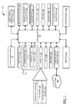
- Figure 1 is a simplified block diagram of components of a portable electronic device in accordance with one example embodiment of the present disclosure.
- Figure 2 is a front view of an example of a portable electronic device in a portrait orientation.
- Figure 3 is a block diagram of a magnetic sensor subsystem in accordance with one example embodiment of the present disclosure.
- Figures 4A to 4C are schematic diagrams illustrating the assignment of pitch and roll vectors of a three-axis accelerometer in accordance with one example embodiment of the present disclosure.
- Figure 5A is a front view of a portable electronic device showing sensing axes of three-axis accelerometer in accordance with one embodiment of the present disclosure.
- Figure 5B is a top view of the portable electronic device of Figure 5A .
- Figure 6 is a simplified block diagram of components of a peripheral device in accordance with one example embodiment of the present disclosure.
- Figure 7 is a simplified block diagram of a communication system suitable for carrying out example embodiments of the present disclosure.
- Figure 8 is a flowchart of a method for device selection using sensory input on a portable electronic device in accordance with one embodiment of the present disclosure.
- the present disclosure generally relates to a portable electronic device such as a handheld electronic device.
- the portable electronic device may be a portable electronic device with or without wireless communication capabilities.
- handheld electronic devices include, but are not limited to, pagers, mobile telephones, smartphones, tablet computing devices, wireless organizers, personal digital assistants, electronic gaming device, digital photograph album, digital camera, and so forth.
- the portable electronic device when a mobile telephone or smartphone, may be provided in any form factor including, but not limited to, a bar-style, brick-style device, slider-style device or flip-style device.
- the teachings of present disclosure may also be applied outside of the portable electronic device.
- the present disclosure provides a solution for detecting, selecting and connecting to peripheral devices from a portable electronic device.
- a magnetic sensor in the portable electronic device is used to detect the location of nearby peripheral devices. After the location of the peripheral devices has been detected, the portable electronic device can select one of the nearby peripheral devices in accordance with selection input. A connection may then be established between the portable electronic device and the selected peripheral device.
- a method for use in a portable electronic device for selecting a peripheral device for connection with the portable electronic device comprising: measuring a magnetic field within the vicinity of the portable electronic device; determining a relative location of at least two available peripheral devices in accordance with magnetic fields uniquely associated with the at least two available peripheral devices; selecting a peripheral device from the at least two available peripheral devices in accordance with the measured magnetic field; and connecting the portable electronic device to the selected peripheral device using a wireless communications path.
- an electronic device comprising: a processor; a magnetic sensor coupled to the processor for detecting a magnetic field within the vicinity of the electronic device; a wireless communication subsystem coupled to the processor; wherein the processor is configured for: measuring a magnetic field within the vicinity of the portable electronic device; selecting a peripheral device from available peripheral devices in accordance with the measured magnetic field; and connecting to the selected peripheral device using a wireless communication path.
- the processor is configured for: determining a relative location of the available peripheral devices in accordance with magnetic fields uniquely associated with particular peripheral devices; receiving a directional input; identifying the peripheral device from the available peripheral devices in accordance with the relative location of the available peripheral devices and the directional input; and selecting the identified peripheral device.
- the electronic device further comprises a touch-sensitive display coupled to the processor, wherein the directional input is a touch gesture received using the touch-sensitive display.
- the electronic device further comprises a motion sensor coupled to the processor, wherein the directional input is a motion gesture using the motion sensor.
- a method for use on a peripheral device of generating a magnetic field comprising: receiving a request from a portable electronic device; sending a response to the portable electronic device generating a magnetic field in response to receiving the request; and connecting to the portable electronic device using a wireless communication path.
- the magnetic field has one or more distinct characteristics which are uniquely associated with the peripheral device.
- the magnetic field is a time varying magnetic field which provides a distinct magnetic signature uniquely associated with the peripheral device.
- the wireless communication path is Bluetooth.
- a peripheral device comprising: a processor; a magnetic signal subsystem coupled to the processor for generating a magnetic field having one or more distinct characteristics; a wireless communication subsystem coupled to the processor; wherein the processor is configured for: receiving a request from a portable electronic device; sending a response to the portable electronic device; generating a magnetic field in response to receiving the request; and connecting to the portable electronic device using a wireless communication path.
- the magnetic field has one or more distinct characteristics which are uniquely associated with the peripheral device.
- the magnetic field is a time varying magnetic field which provides a distinct magnetic signature uniquely associated with the peripheral device.
- the wireless communication path is Bluetooth.
- a computer program product comprising a computer readable medium having stored thereon computer program instructions for implementing a method on an electronic device, the computer executable instructions comprising instructions for performing the method(s) set forth herein.
- FIG. 1 illustrates in block diagram form, a portable electronic device 100 to which example embodiments described in the present disclosure can be applied.
- the portable electronic device 100 includes multiple components, such as a processor 102 that controls the overall operation of the portable electronic device 100. Communication functions, including data and voice communications, are performed through a communication subsystem 104. Data received by the portable electronic device 100 is decompressed and decrypted by a decoder 106. The communication subsystem 104 receives messages from and sends messages to a wireless network 150.
- the wireless network 150 may be any type of wireless network, including, but not limited to, data wireless networks, voice wireless networks, and networks that support both voice and data communications.
- a power source 142 such as one or more rechargeable batteries or a port to an external power supply, powers the portable electronic device 100.
- the processor 102 interacts with other components, such as Random Access Memory (RAM) 108, memory 110 such as flash memory, a display 112 (such as a liquid crystal display (LCD)) with a touch-sensitive overlay 114 operably coupled to an electronic controller 116 that together comprise a touch-sensitive display 118, one or more keys or buttons 120, a navigation device 122, a magnetic sensor subsystem 123, one or more auxiliary input/output (I/O) subsystems 124, a data port 126, a speaker 128, a microphone 130, a short-range wireless communication subsystem 132, other device subsystems 134 and a motion detection subsystem 136.
- RAM Random Access Memory
- memory 110 such as flash memory
- a display 112 such as a liquid crystal display (LCD)
- a touch-sensitive overlay 114 operably coupled to an electronic controller 116 that together comprise a touch-sensitive display 118, one or more keys or buttons 120, a navigation device 122, a magnetic sensor subsystem 123, one
- GUI graphical user interface
- buttons 120 are located below the touch-sensitive display 118 on a front face of the portable electronic device 100.
- the buttons 120 generate corresponding input signals when activated.
- the buttons 120 may be constructed using any suitable button (or key) construction such as, for example, a dome-switch construction.
- the actions performed by the device 100 in response to activation of respective buttons 120 are context-sensitive. The action performed depends on a context that the button was activated.
- the context may be, but is not limited to, a device state, application, screen context, selected item or function, or any combination thereof.
- buttons 120 are an answer (or send) button 120A, menu button 120B, escape (or back) button 120C, and a hang up (or end) button 120D.
- the send/answer button 120A may be used for answering an incoming voice call, invoking a menu for a phone application when there is no voice call in progress, or initiating an outbound voice phone call from the phone application when a phone number is selected in the phone application.
- the menu button 120B may be used to invoke a context-sensitive menu comprising context-sensitive menu options.
- the escape/back button 120C may be used to cancel a current action, reverse (e.g., "back up” or “go back") through previous user interface screens or menus displayed on the touch-sensitive display 118, or exit the current application 148.
- the end/hang up button 120D may be used to end a voice call in progress or hide the current application 148.
- the navigation device 122 may be a depressible (or clickable) joystick such as a depressible optical joystick, a depressible trackball, a depressible scroll wheel, or a depressible touch-sensitive trackpad or touchpad.
- a depressible optical joystick as shown in Figure 2
- movements of the user's finger such as vertical and horizontal movements, are detected by an optical sensor of the optical joystick.
- Up, down, left or right movements detected by the optical joystick are interpreted as corresponding up, down, left or right navigation commands.
- navigation via the optical joystick is by 1:1 movement so that each directional gesture or movement detected by the optical joystick causes a corresponding navigation movement.
- the auxiliary I/O subsystems 124 may include other input devices such as a keyboard or keypad.
- the portable electronic device 100 uses a Subscriber Identity Module or a Removable User Identity Module (SIM/RUIM) card 138 for communication with a network, such as the wireless network 150.
- SIM/RUIM Removable User Identity Module
- user identification information may be programmed into memory 110.
- the short-range wireless communication subsystem 132 provides a short-range wireless communication interface.
- the short-range wireless communication interface is typically Bluetooth® interface but may be another type of short-range wireless communication interface including, but not limited to, an infrared (IR) interface such as an Infrared Data Association (IrDA) interface, an IEEE 802.15.3a interface (also referred to as UltraWideband (UWB)), Z-Wave interface, ZigBee interface or other suitable short-range wireless communication interface.
- IR infrared
- IrDA Infrared Data Association
- IEEE 802.15.3a interface also referred to as UltraWideband (UWB)
- Z-Wave interface also referred to as UltraWideband (UWB)
- ZigBee interface ZigBee interface
- the portable electronic device 100 includes an operating system 146 and software applications 148 that are executed by the processor 102 and are typically stored in a persistent, updatable storage such as the memory 110. Additional applications 148 may be loaded onto the portable electronic device 100 through the wireless network 150, the auxiliary I/O subsystem 124, the data port 126, the short-range wireless communication subsystem 132, or any other suitable subsystem 134.
- the applications 148 include a device selection module 162 for selecting peripheral devices using sensory input, as described more fully below.
- the device selection module 162 may be a standalone application or part of the operating system 146.
- a received signal such as a text message, an e-mail message, or web page download is processed by the communication subsystem 104 and input to the processor 102.
- the processor 102 processes the received signal for output to the display screen 112 and/or to the auxiliary I/O subsystem 124.
- a subscriber may generate data items, for example e-mail messages, which may be transmitted over the wireless network 150 through the communication subsystem 104.
- the speaker 128 outputs audible information converted from electrical signals
- the microphone 130 converts audible information into electrical signals for processing.
- FIG 2 shows a front view of an example of the portable electronic device 100 in portrait orientation.
- the portable electronic device 100 includes a housing 200 that houses internal components including internal components shown in Figure 1 and frames the touch-sensitive display 118 such that the touch-sensitive display 118 is exposed for user-interaction therewith when the portable electronic device 100 is in use.
- the touch-sensitive display 118 may include any suitable number of user-selectable features rendered thereon, for example, in the form of virtual buttons for user-selection of, for example, applications, options, or keys of a keyboard for user entry of data during operation of the portable electronic device 100.
- the touch-sensitive display 118 may be any suitable touch-sensitive display, such as a capacitive, resistive, infrared, surface acoustic wave (SAW) touch-sensitive display, strain gauge, optical imaging, dispersive signal technology, acoustic pulse recognition, and so forth, as known in the art.
- a capacitive touch-sensitive display includes a capacitive touch-sensitive overlay 114.
- the overlay 114 may be an assembly of multiple layers in a stack including, for example, a substrate, a ground shield layer, a barrier layer, one or more capacitive touch sensor layers separated by a substrate or other barrier, and a cover.
- the capacitive touch sensor layers may be any suitable material, such as patterned indium tin oxide (ITO).
- One or more touches may be detected by the touch-sensitive display 118.
- the processor 102 may determine attributes of the touch, including a location of a touch.
- Touch location data may include an area of contact or a single point of contact, such as a point at or near a centre of the area of contact.
- the location of a detected touch may include x and y components, e.g., horizontal and vertical components, respectively, with respect to one's view of the touch-sensitive display 118.
- the x location component may be determined by a signal generated from one touch sensor
- the y location component may be determined by a signal generated from another touch sensor.
- a signal is provided to the controller 116 in response to detection of a touch.
- a touch may be detected from any suitable object, such as a finger, thumb, appendage, or other items, for example, a stylus, pen, or other pointer, depending on the nature of the touch-sensitive display 118. Multiple simultaneous touches may be detected.
- a touch and hold gesture is detected or recognized when a touch event occurs for a duration which is greater than or equal to a threshold duration.
- the threshold duration may be, for example, 400 milliseconds in some embodiments. Other threshold durations are possible.
- a tap gesture is detected or recognized when a touch event occurs for a duration which is less than the threshold duration.
- a tap gesture requires both a finger down and lift off within the threshold duration to be detected by the touch-sensitive display 118.
- a touch and hold gesture requires only a finger down for the threshold duration before the touch-sensitive display 118 detects the touch and hold gesture.
- a one-finger touch and hold gesture occurs when a user touches a selectable onscreen item on the touch-sensitive display 118, such as a button or menu item, with one finger and holds the finger in contact with the touch-sensitive display 118 for a duration which exceeds the threshold duration.
- a two-finger touch and hold gesture occurs when a user touches a selectable onscreen item on the touch-sensitive display 118 with two-fingers and holds both fingers in contact with the touch-sensitive display 118 for a duration which exceeds the threshold duration. Touching a selectable onscreen item comprises touching a location of the touch-sensitive display 118 which is coincident with the selectable onscreen item displayed on the display screen 112.
- a location is coincident with the selectable onscreen item in that the centroid of the touch event is within an input area of the user interface screen assigned for receiving input for activating the selectable onscreen item.
- the input area of the selectable onscreen item may be different than the displayed area of the selectable onscreen item on the display screen 112 in some embodiments, typically the input area being larger than the displayed area in such embodiments to accommodate touch offset of the user.
- a swipe gestures has a single direction which is evaluated with respect to an initial contact point (e.g., centroid) of the touch event at which the finger makes contact with the touch-sensitive display 118 and a terminal or ending contact point at which the finger is lifted from the touch-sensitive display 118 while in motion. This may reduce processing as the processor 102 does not utilize the information from all contact points of the entire gesture to resolve the direction of the touch gesture.
- an initial contact point e.g., centroid
- swipe gestures include a horizontal swipe gesture, a vertical swipe gesture, and a diagonal swipe gesture.
- a horizontal swipe gesture typically comprises an initial contact with the touch-sensitive display 118 towards its left or right edge to initialize the gesture, followed by a horizontal movement of the point of contact from the location of the initial contact to the opposite edge while maintaining continuous contact with the touch-sensitive display 118, and a breaking of the contact at the opposite edge of the touch-sensitive display 118 to complete the horizontal swipe gesture.
- a vertical swipe gesture typically comprises an initial contact with the touch-sensitive display 118 towards its top or bottom edge to initialize the gesture, followed by a vertical movement of the point of contact from the location of the initial contact to the opposite edge while maintaining continuous contact with the touch-sensitive display 118, and a breaking of the contact at the opposite edge of the touch-sensitive display 118 to complete the vertical swipe gesture.
- a diagonal swipe gesture typically comprises an initial contact with the touch-sensitive display 118 towards a corner to initialize the gesture, followed by a diagonal movement of the point of contact from the location of the initial contact to the opposite corner while maintaining continuous contact with the touch-sensitive display 118.
- the processor 102 uses the initial contact point and the end contact point, determines the direction of the gesture. For example, a horizontal swipe gesture could correspond to either a left or right direction.
- Swipe gestures can be of various lengths, can be initiated in various places on the touch-sensitive display 118, and need not span the full dimension of the touch-sensitive display 118.
- breaking contact of a swipe can be gradual in that contact pressure on the touch-sensitive display 118 is gradually reduced while the swipe gesture is still underway.
- the touch-sensitive display 118 is described herein in the context of fingers of a device user for purposes of convenience only. It will be appreciated that a stylus or other object may be used for interacting with the touch-sensitive display 118 depending on the type.
- the motion detection subsystem 136 comprises at least one sensor which is coupled to the processor 102 and which is controlled by one or a combination of a monitoring circuit and operating software.
- the sensor has a sensing element which detects acceleration from motion and/or gravity.
- the sensor generates and outputs an electrical signal representative of the detected acceleration. Changes in movement of the portable electronic device 100 result in changes in acceleration which produce corresponding changes in the electrical signal output of the sensor.
- the sensor may be an accelerometer, such as a three-axis accelerometer having three mutual orthogonally sensing axes.
- the accelerometer may be digital or analog depending on the embodiment.
- the accelerometer may be utilized to detect acceleration of the portable electronic device 100, such as a direction of gravitational forces or gravity-induced reaction forces.
- Other types of motion sensors may be used by the motion detection subsystem 136 in addition to, or instead of, an accelerometer.
- the other motion sensors may comprise a proximity sensor, gyroscope, or both, which detect changes in the proximity and orientation of portable electronic device
- Changes in acceleration, proximity and orientation detected by the accelerometer, proximity sensor and/or gyroscope may be interpreted by the portable electronic device 100 as motion of the portable electronic device 100.
- the changes in acceleration, proximity and orientation are within threshold tolerance(s) of regularity or predictability, the changes in acceleration, proximity and orientation match predetermined motion criteria (e.g., stored in the memory 110) and the changes may be interpreted by the portable electronic device 100 as a pattern of motion. Multiple patterns of motion may be recognized by the portable electronic device 100.
- the accelerometer has three mutually orthogonal sensing axes denoted "x", "y” and "z”.
- the x-axis and y-axis are aligned with a horizontal plane defined with respect to the portable electronic device 100.
- the z-axis is perpendicular to the horizontal plane of the portable electronic device 100. The z-axis will detect when portable electronic device 100 is moved vertically.
- the x-axis is aligned about an axis extending laterally along the midpoint of the portable electronic device 100 between the top and bottom ends respectively.
- the y-axis is aligned about an axis extending longitudinally along the midpoint of the portable electronic device 100 between the left and right sides respectively.
- the z-axis extends perpendicularly through the x-y plane defined by the x and y axes at the intersection (origin) of these axes. It is contemplated that the "x", “y” and “z” axes may be aligned with different features of the portable electronic device 100 in other embodiments.
- the z-axis measures 1 g in the z-axis.
- the z-axis baseline reading is moved downwards away from 1 g level.
- pitch ( ⁇ ) is the angle of the x-axis relative to the ground.
- ⁇ is the angle of the z-axis relative to gravity.
- roll (p) is the angle of the y-axis relative to the ground. It will be appreciated that rotation may occur about any combination of sensing axes.
- the concepts and methodology described herein can be applied to any orientation and any combination of pitch ( ⁇ ), roll (p) angles, and ⁇ (the angle of the z-axis relative to gravity).
- the pitch ( ⁇ ), roll (p) and the angle of the z-axis relative to gravity ( ⁇ ) may be determined, for example, using standard equations.
- the magnetic sensor subsystem 122 comprises at least one magnetic sensor 302.
- the magnetic sensor 302 is a magnetometer which senses and measures the strength and/or direction of the magnetic field within the vicinity of the portable electronic device 100.
- the magnetic field measured by the magnetic sensor 302 may be the Earth's magnetic field, a magnetic field generated by one or more magnets in a peripheral device 600 (also known as an accessory device and described in more detail below), or a combination thereof.
- the magnetic sensor 302 when operable, obtains or otherwise acquires readings including the direction of the magnetic field within the vicinity of the portable electronic device 100 and its strength.
- the vicinity in which the magnetic sensor 302 is capable of detecting and measuring the direction and strength of the magnetic field is the area immediately surrounding the portable electronic device 100.
- the range of the magnetic sensor 302, i.e. the size of the area surrounding the portable electronic device 100 in which the magnetic sensor 302 can measure the magnetic field depends on the particular type of magnetic sensor 302 which is used in a given embodiment.
- the readings are stored in a magnetic sensor readings data store (not shown) in memory 110.
- Various applications 148 such as a compass application (not shown), may utilize the readings in the data store.
- the applications 148 may use readings in the data store to determine a relative location (or directional heading) of a peripheral device 600 in accordance with a detected magnetic field generated by one or more magnets in the peripheral device 600.
- the applications 148 may also provide a user interface (UI) on the display 112, e.g. a real-time compass showing heading of the portable electronic device 100.
- UI user interface
- the magnetic sensor 302 may be digital or analog depending on the embodiment.
- the magnetic sensor 302 in at least some examples, may be a three-axis magnetometer having three mutually orthogonal sensing axes denoted "x", "y” and "z".
- the direction and strength of a magnetic field detected by the magnetic sensor 302 can be represented by the three axis values Hx, Hy and Hz.
- a relative location can be determined by using the Hx and Hy and optionally Hz components of the magnetic field.
- a relative location can be determined by using only the Hx and Hy components of the magnetic field, that is, the directions planar with the Earth's surface.
- the Hx and Hy components of the magnetic field may be used, for example, when the portable electronic device 100 is positioned horizontally (e.g., when held flat by the user or placed on a flat surface).
- the relative location of a peripheral device 600 can be determined from the x and y readings of the magnetic sensor 302, for example, using standard equations. The relative location may be determined in degrees or other suitable form.
- the peripheral device 600 includes a magnet which generates a magnetic field having one or more distinct characteristics that may be uniquely associated with the peripheral device 600. This allows the magnetic field generated by the peripheral device 600 to be differentiated from the Earth's magnetic field and other sources such as a magnetic field generated by other peripheral devices 600.
- the processor 102 can identify the particular peripheral device 600 associated with the detected magnetic field.
- the portable electronic device 100 may be connected to one or a number of peripheral devices 600 which each generate a time varying magnetic field.
- the time varying magnetic field provides a distinct magnetic signature which is uniquely associated with a particular peripheral device 600.
- the time varying magnetic field may be generated, for example, by a variable electromagnet.
- the magnetic sensor 302 may include a Hall Effect sensor for each sensing axis.
- a Hall Effect sensor is made of a semiconductor material, such as silicon, and has a flat rectangular shape.
- a Hall Effect sensor may be actuated by applying a current to its longitudinal ends so that the current flows longitudinally through the sensor.
- the longitudinal ends of the Hall Effect sensor are coupled to a regulated voltage source (not shown) and ground (not shown), respectively.
- a voltage differential is created across the sensor at its output(s) when a magnetic flux of proper polarity passes perpendicularly through the plane of the Hall Effect sensor.
- the magnitude of the voltage created is proportional to the magnetic flux density of the vertical component of the magnetic field.
- the output of the magnetic sensor 302 is coupled to a differential amplifier 304.
- the differential amplifier 304 is coupled in parallel to the voltage source and ground.
- the differential amplifier 304 amplifies the voltage output of the Hall Effect sensor to produce an amplified output which is proportional to the magnetic flux density passing through the Hall Effect sensor.
- the output of the differential amplifier 304 is a signal proportional to magnetic flux density being received by the Hall Effect sensor.
- the output of the differential amplifier 304 is sent to an analog-to-digital converter (ADC) 306 which converts the analog values to digital values.
- ADC analog-to-digital converter
- the output of the ADC 306 is coupled to the processor 102 which receives the digital value as input for analysis.
- the output of the differential amplifier 304 may be sent to and analysed by a dedicated controller (not shown) which is coupled to the processor 102 via interrupt ports and optionally serial data ports.
- a dedicated controller not shown
- the relationship between the magnetic flux density of a magnetic field and the relative location or directional heading of a peripheral device 600 having a magnet which generates a magnetic field is stored in the memory 110 or an internal memory of the dedicated controller, for example, in firmware. The relationship may be defined, for example, by an equation or series of equations, or empirical data.
- the processor 102 compares magnetic flux density to one or more predetermined criteria to determine a location of the magnet relative to the portable electronic device 100.
- the relative location of the peripheral device 600 magnet may be determined, for example, as a coordinate value in two dimensional (e.g., x and y) or three dimensional (e.g., x, y and z) coordinate space using the relationship between the magnetic flux density and relative location.
- the peripheral device 600 is an electronic device which connects to a host portable electronic device 100.
- the peripheral device 600 expands the capabilities of the host portable electronic device 100 but does not form part of the portable electronic device 100, and is largely dependent on the host portable electronic device 100 for its control and operation.
- the peripheral device 600 and portable electronic device 100 in at least some examples, may have a master-slave relationship in which the operation of the peripheral device 600 is controlled by the host portable electronic device 100.
- Peripheral devices 600 are sometimes referred to as accessories or external devices.
- peripheral device 600 examples include, but are not limited to, an input device (such as a keyboard, mouse, touchpad, camera or microphone), output device (such as a display, speaker(s), ear-bud or headphones), hands-free calling device, navigation device (such as a Global Positioning System (GPS) navigation device), home theatre or stereo system, electronic gaming device, digital photograph album (such as a digital picture frame) or digital camera.
- the peripheral device 600 may be another portable electronic device 100, for example, the peripheral device 600 may be a tablet computing device (commonly known as a tablet) used as a display for output.
- the peripheral device 600 includes multiple components, such as a processor 602 that controls the overall operation of the peripheral device 600.
- the processor 602 interacts with other components, such as RAM 608, memory 610 such as flash memory, display 612 such as an LCD, input device 620 such as a push button, magnetic signal subsystem 622, data port 626, short-range wireless communication subsystem 632, and power source 642, such as one or more rechargeable batteries or a port to an external power supply, powers the peripheral device 600.
- the processor 602 operates under stored program control with software stored in the memory 610 or firmware.
- the stored programs include an operating system 646 and software applications 648 that are executed by the processor 602.
- the applications 648 include a signal generation module 662 for generating a magnetic field, for example, in response to an instruction received from the portable electronic device 100 over the short-range wireless communication subsystem 632.
- the signal generation module 662 may be a standalone application or part of the operating system 646.
- the peripheral device 600 can connect to the portable electronic device 100 using the short-range wireless communication subsystem 632 and possibly the data port 626.
- the short-range wireless communication subsystem 632 provides a short-range wireless communication interface and is of the same type as the short-range wireless communication subsystem 132 of the portable electronic device 100.
- the short-range wireless communication interface 632 is typically Bluetooth® interface but may be another type of short-range wireless communication interface including, but not limited to, an IR interface such as an IrDA interface, an IEEE 802.15.3a interface (or UWB), Z-Wave interface, ZigBee interface or other suitable short-range wireless communication interface.
- the magnetic signal subsystem 622 includes an electric-to-magnetic transducer (not shown), typically in the form of a wire coil, which converts electrical signals received from the processor 602 into magnetic signals which form a magnetic field having one or more distinct characteristics that may be uniquely associated with a particular peripheral device 600.
- the magnetic signals may be magnetic representations of a designated electrical signal such as designated waveform.
- the magnetic signals form a varying magnetic field which varies with respect to time similar to a hearing aid compatibility (HAC) coil.
- HAC hearing aid compatibility
- the time varying magnetic field generated by the magnetic signal subsystem 622 provide a variable electromagnet and may be used to provide a distinct magnetic signature which is uniquely associated with a particular peripheral device 600.
- the magnetic field generated by the magnetic signal subsystem 622 may be detected by the magnetic sensor subsystem 123 of the portable electronic device 100 when located in sufficient proximity to the peripheral device 600.
- the processor 102 of the portable electronic device 100 can identify the particular peripheral device 600 associated with the detected magnetic field.
- Parameters describing one or more distinct characteristics of the magnetic field generated by the known peripheral devices 600 may be stored in the memory 110 of the portable electronic device 100 during a pairing process to enable short-range wireless communication between the portable electronic device 100 and peripheral devices 600.
- the short-range wireless communication interface is used for communication between the portable electronic device 100 and peripheral devices 600 is Bluetooth in at least some examples; however, other short-range wireless communication technologies may be used in other embodiments.
- the portable electronic device 100 receives identifying information (such as a name and Media Access Control (MAC) address) from the peripheral device 600 during the pairing process.
- identifying information such as a name and Media Access Control (MAC) address
- the parameters describing one or more distinct characteristics of the magnetic field may be provided by the peripheral device 600, or may be determined by the portable electronic device 100 during pairing in response to generation of the magnetic field by the peripheral device 600.
- Other data may be exchanged between the portable electronic device 100 and peripheral device 600 during pairing. Pairing information, the identifying information and the parameters describing one or more distinct characteristics of the magnetic field generated by the peripheral device 600, is stored in a profile, for example in the Bluetooth profile, in the memory 110 of the portable electronic device 100 for the respective peripheral device 600.
- the communication system 700 includes one or more portable electronic device 100 (only one of which is shown in Figure 7 ) that are enabled to communicate with the wireless network 150.
- the wireless network 150 may be, but is not limited to a, Wireless Wide Area Network (WWAN) or Wireless Local Area Network (WLAN) that conforms to IEEE 802.11 standards such as 802.11 a/b/g/n.
- the wireless network 150 may be connected through intermediate communications links 702, comprising for example the Internet, to one or more private communication networks 704 such as an enterprise network.
- a portable electronic device 100 may wirelessly connect to a peripheral device 600 using a short-range wireless communication path 706.
- the short-range wireless communication path 706 may be a wireless personal area network (WPAN) or WLAN connection.
- the short-range wireless communication path 706 is typically a Bluetooth connection but may be another type of short-range wireless communication connection, including but not limited to, an IR connection such as an IrDA connection, UWB connection, Z-Wave connection, ZigBee connection or other suitable short-range wireless communication connection.
- a flowchart illustrating one example embodiment of a method 800 for connecting electronic devices is shown in Figure 8 .
- the method is performed partly on the portable electronic device 100 and partly on a peripheral device 600.
- the method 800 may be carried out at least in part by software in the form of the device selection module 162 and signal generation module 662 which are executed, by the processors 102, 602 of the portable electronic device 100 and peripheral device 600 respectively. Coding of software for carrying out the method 800 is within the scope of a person of ordinary skill in the art provided the present disclosure.
- the method 800 may contain additional or fewer processes than shown and/or described, and may be performed in a different order.
- Computer-readable code executable by the processors 102, 602 to perform the method 800 may be stored in a computer-readable medium of the portable electronic device 100 and peripheral device 600 respectively such as the memory 110, 610.
- the processor 102 monitors for and detects input to connect to a peripheral device 600 when the portable electronic device 100 is not connected to a peripheral device 600, or input to change (or switch) a peripheral device 600 with which the portable electronic device 100 is connected over the short-range wireless communication path 706 when the portable electronic device 100 is already connected to one or more peripheral devices 600 (802). It will be appreciated that the portable electronic device 100 may connect to multiple peripheral devices 600 over the short-range wireless communication path 706 (e.g., Bluetooth).
- the short-range wireless communication path 706 e.g., Bluetooth
- a portable electronic device 100 such as a handheld electronic device is Bluetooth-paired with multiple peripheral devices 600.
- At least one of the peripheral devices 600 such as a tablet, includes a relatively large display viewing content.
- a user may desire to view an attachment to an electronic message (e.g., email), downloaded content, or streamed content on one of the paired peripheral devices 600 but may want to select a particular one of the peripheral devices 600.
- the portable electronic device 100 When input to connect to a peripheral device 600, or input to change a peripheral device 600 is received, the portable electronic device 100 actively scans for Bluetooth-enabled peripheral devices 600 by sending probe requests to all Bluetooth-enabled peripheral devices 600 having a Bluetooth profile stored in memory 110 (i.e., all Bluetooth-enabled peripheral devices 600 with which the portable electronic device 100 is paired) at 804.
- the probe requests are a type of status request which requests that all Bluetooth-enabled peripheral devices provide identifying information and possibly a signal quality indication in a probe response.
- the format and content of Bluetooth probe requests and responses are well known in the art as are probe requests and responses for other types of short-range wireless communication connections.
- the portable electronic device 100 may be paired with a number of Bluetooth-enabled peripheral devices 600 such as a tablet, ear-bud and hands-free calling device.
- Each Bluetooth-enabled peripheral device 600 with which the portable electronic device 100 is paired has its own Bluetooth profile stored in memory 110.
- the processor 602 of the peripheral devices 600 causes a probe response to be sent (e.g., a Bluetooth probe response) using the short-range wireless communication subsystem 632 and causes the magnetic signal subsystem 622 to generate a magnetic field having one or more distinct characteristics that may be uniquely associated with the respectively particular peripheral devices 600.
- the magnetic field may be a time varying magnetic field which provides a distinct magnetic signature which is uniquely associated with a particular peripheral device 600.
- the time varying magnetic field generated by the peripheral devices 600 may vary in period, offset and/or amplitude.
- the time varying magnetic field generated by the peripheral devices 600 may be of a distinct waveform type, such as a sinusoidal wave, square wave, triangular wave, saw tooth wave or pulse wave, which varies in period, offset and/or amplitude.
- the identifying information and possibly a signal quality indication of the available peripheral devices 600 are determined from incoming connection requests received by the portable electronic device 100 from the available peripheral devices 600.
- the portable electronic device 100 receives responses from the available peripheral devices 600.
- the processor 102 determines whether any peripheral devices 600 are available in accordance with whether any responses to the probe requests are received.
- the processor 102 may also determine the available peripheral devices 600 from the responses to the probe requests which are received (806).
- the portable electronic device 100 then measures the magnetic field within the vicinity of the portable electronic device 100 using the magnetic sensor subsystem 123, for example, using the magnetic sensor 302 (808).
- the magnetic field measured by the magnetic sensor 302 may be the Earth's magnetic field, a time varying magnetic field generated by available peripheral devices 600, or a combination thereof.
- the processor 102 determines a relative location (or directional heading) of available peripheral devices 600 in accordance with the measured magnetic field (810).
- the portable electronic device 100 may use digital signal processing algorithms to differentiate between the Earth's magnetic field and the magnetic field generated by available peripheral devices 600. This may involve differentiating and analyzing static and time varying magnetic fields.
- the measured magnetic field(s) are compared to stored parameters describing the magnetic fields generated by known peripheral devices 600. When the measured magnetic field matches parameters for a known peripheral device 600, a peripheral device 600 is identified.
- the stored parameters describe one or more distinct characteristics of the magnetic field generated by the known peripheral devices 600.
- the peripheral devices 600 each generate a time varying magnetic field, the stored parameters may comprise a period, offset and/or amplitude of the time varying magnetic field. As noted above, the time varying magnetic field provides a distinct magnetic signature which is uniquely associated a particular peripheral device 600.
- a relative location can be determined by using only the Hx and Hy component of the magnetic field, that is, the directions planar with the Earth's surface, for example, when the portable electronic device 100 is positioned horizontally (e.g., when held flat by the user or placed on a flat surface).
- a prompt for the user to place the portable electronic device 100 in a substantially horizontal position, such as on a flat surface, may be displayed on the display 112 prior to measuring the magnetic field in the within the vicinity of the portable electronic device 100 in 802.
- the prompt may be displayed, for example, in response to receiving input to connect to a peripheral device 600 or input to change a peripheral device 600.
- the processor 102 monitors for and detects selection input selecting one of the available peripheral devices 600 received by an input device, such as the touch-sensitive display 118, motion detection subsystem 136 or navigation device 122.
- the processor 102 selects an available peripheral device 606 in accordance with the selection input (812).
- the selection input may comprise a directional input.
- the selection input may be touching (or touching and holding) an onscreen button displayed on the touch-sensitive display 118 corresponding to a particular one of the available peripheral devices 600, depressing a designated button 120 corresponding to a particular one of the available peripheral devices 600, or depressing a designated key in a keyboard or keypad corresponding to a particular one of the available peripheral devices 600, or other suitable selection input.
- the directional input may be a touch gesture sensed by the touch-sensitive display 118, a motion gesture sensed by motion detection subsystem 136, a navigational input received by the navigation device 122 or other suitable directional input.
- the directional input may be a swipe gesture having an identifiable direction, or possibly another type of directional touch gesture having an identifiable direction.
- the motion gesture may be limited to a specific type of motion gesture having an identifiable direction, such as a pointing gesture, or may be any type of motion gesture having an identifiable direction.
- the navigational input may be a directional movement sensed by navigation device 122 such as a depressible optical joystick.
- the directional movement sensed by the navigation device 122 may be a vertical or horizontal movement, such as an up, down, left or right movement, or possibly a diagonal movement such as an upright, up-left, down-right or down-left movement.
- the processor 102 selects the available peripheral device 606 by comparing the directional input with the relative locations of the available peripheral devices 600, determining which of the available peripheral devices 606 has a relative location (or heading) nearest to a direction of the directional input, and selecting the available peripheral device 606 having a relative location (or heading) nearest to the direction of the directional input.
- a prompt may be displayed on the touch-sensitive display 118 to notify the user to provide the directional input or other selection input.
- the prompt “Point Handheld at (New) Bluetooth Device” may be displayed on the touch-sensitive display 118.
- the prompt “Perform Swipe in Direction of (New) Bluetooth Device” may be displayed on the touch-sensitive display 118.
- the prompt “Move Navigation Device in Direction of (New) Bluetooth Device” may be displayed on the touch-sensitive display 118.
- the navigation device 122 is a depressible optical joystick
- the prompt “Perform Swipe in Direction of (New) Bluetooth Device” may be displayed on the touch-sensitive display 118.
- the processor 102 connects to the selected peripheral device 606 using the short-range wireless communication path 706 (e.g., Bluetooth) at 814.
- the processor 102 may automatically select the peripheral device 600 without selection input.
- selection input may not be required. Instead, automatic selection of a peripheral device 600 from multiple peripheral device 600 which are available may be performed using a priority list or other scheme which ranks peripheral devices 600 with which the portable electronic device 100 has been paired in a connection order which describes the order in which the portable electronic device 100 selects peripheral devices 600 for connection.
- the present disclosure provides a method of device selection using sensory input which is more intuitive and possibly faster than conventional methods which require users to navigate cumbersome hierarchical menus in order to locate and select the appropriate menu options to connect to a peripheral device 600, or change a peripheral device 600 to which the portable electronic device 100 is connected.
- the method provided is relatively simple and intuitive, thereby facilitating user adoption.
Landscapes
- Engineering & Computer Science (AREA)
- Theoretical Computer Science (AREA)
- General Engineering & Computer Science (AREA)
- Computer Networks & Wireless Communication (AREA)
- Computer Hardware Design (AREA)
- Signal Processing (AREA)
- Human Computer Interaction (AREA)
- Physics & Mathematics (AREA)
- General Physics & Mathematics (AREA)
- Computer Security & Cryptography (AREA)
- Telephone Function (AREA)
- User Interface Of Digital Computer (AREA)
Priority Applications (2)
| Application Number | Priority Date | Filing Date | Title |
|---|---|---|---|
| EP11165051.1A EP2521342B1 (fr) | 2011-05-06 | 2011-05-06 | Procédé de sélection de dispositif au moyen d'entrées de capteur et dispositif électronique portable configuré pour cela |
| CA2775662A CA2775662C (fr) | 2011-05-06 | 2012-04-30 | Methode de selection de dispositif par intrant sensoriel et dispositif electronique configure pour cette tache |
Applications Claiming Priority (1)
| Application Number | Priority Date | Filing Date | Title |
|---|---|---|---|
| EP11165051.1A EP2521342B1 (fr) | 2011-05-06 | 2011-05-06 | Procédé de sélection de dispositif au moyen d'entrées de capteur et dispositif électronique portable configuré pour cela |
Publications (2)
| Publication Number | Publication Date |
|---|---|
| EP2521342A1 true EP2521342A1 (fr) | 2012-11-07 |
| EP2521342B1 EP2521342B1 (fr) | 2017-03-22 |
Family
ID=44582051
Family Applications (1)
| Application Number | Title | Priority Date | Filing Date |
|---|---|---|---|
| EP11165051.1A Not-in-force EP2521342B1 (fr) | 2011-05-06 | 2011-05-06 | Procédé de sélection de dispositif au moyen d'entrées de capteur et dispositif électronique portable configuré pour cela |
Country Status (2)
| Country | Link |
|---|---|
| EP (1) | EP2521342B1 (fr) |
| CA (1) | CA2775662C (fr) |
Cited By (5)
| Publication number | Priority date | Publication date | Assignee | Title |
|---|---|---|---|---|
| DE102013218005A1 (de) * | 2013-01-02 | 2014-07-03 | Htc Corporation | Verfahren zum Teilen von Daten zwischen Geräten |
| WO2014128703A1 (fr) | 2013-02-21 | 2014-08-28 | Wise-Sec Ltd. | Détection de proximité |
| WO2016007059A1 (fr) * | 2014-07-09 | 2016-01-14 | Cumbari Ab | Procédé et système d'acquisition de connaissance de proximité d'un dispositif électronique par un autre dispositif pour établir une communication |
| EP3094122A1 (fr) * | 2015-05-13 | 2016-11-16 | Assa Abloy Ab | Systèmes et procédés pour protéger des informations sensibles stockées sur un dispositif mobile |
| US20240143139A1 (en) * | 2022-11-01 | 2024-05-02 | Phunware, Inc. | Proximity-enabled machine control system |
Citations (3)
| Publication number | Priority date | Publication date | Assignee | Title |
|---|---|---|---|---|
| EP1447944A2 (fr) * | 2003-02-17 | 2004-08-18 | Samsung Electronics Co., Ltd. | Appareil de communication Bluetooth et méthode de notification des utilisateurs d'appareils connectant aux réseaux ad-hoc pour établir des connexions effectives dépendant de la sélection de l'utilisateur |
| US20070066323A1 (en) * | 2005-09-22 | 2007-03-22 | Korea Advanced Institute Of Science And Technology | Intuitive real spatial aiming-based system, identification and communication methods using the same |
| WO2011049762A1 (fr) * | 2009-10-21 | 2011-04-28 | Apple Inc. | Procédé et appareil de déclenchement de découverte de dispositif réseau |
-
2011
- 2011-05-06 EP EP11165051.1A patent/EP2521342B1/fr not_active Not-in-force
-
2012
- 2012-04-30 CA CA2775662A patent/CA2775662C/fr active Active
Patent Citations (3)
| Publication number | Priority date | Publication date | Assignee | Title |
|---|---|---|---|---|
| EP1447944A2 (fr) * | 2003-02-17 | 2004-08-18 | Samsung Electronics Co., Ltd. | Appareil de communication Bluetooth et méthode de notification des utilisateurs d'appareils connectant aux réseaux ad-hoc pour établir des connexions effectives dépendant de la sélection de l'utilisateur |
| US20070066323A1 (en) * | 2005-09-22 | 2007-03-22 | Korea Advanced Institute Of Science And Technology | Intuitive real spatial aiming-based system, identification and communication methods using the same |
| WO2011049762A1 (fr) * | 2009-10-21 | 2011-04-28 | Apple Inc. | Procédé et appareil de déclenchement de découverte de dispositif réseau |
Cited By (16)
| Publication number | Priority date | Publication date | Assignee | Title |
|---|---|---|---|---|
| US9037085B2 (en) | 2013-01-02 | 2015-05-19 | Htc Corporation | Method for sharing data between devices |
| DE102013218005A1 (de) * | 2013-01-02 | 2014-07-03 | Htc Corporation | Verfahren zum Teilen von Daten zwischen Geräten |
| DE102013218005B4 (de) | 2013-01-02 | 2020-06-18 | Htc Corporation | Verfahren zum Teilen von Daten zwischen Geräten |
| CN105122783B (zh) * | 2013-02-21 | 2019-02-01 | 外兹-赛克有限公司 | 接近度检测 |
| WO2014128703A1 (fr) | 2013-02-21 | 2014-08-28 | Wise-Sec Ltd. | Détection de proximité |
| CN105122783A (zh) * | 2013-02-21 | 2015-12-02 | 外兹-赛克有限公司 | 接近度检测 |
| JP2016515323A (ja) * | 2013-02-21 | 2016-05-26 | ワイズ−セック・リミテッド | 近接検出 |
| EP2959670A4 (fr) * | 2013-02-21 | 2017-02-15 | Wise-sec Ltd. | Détection de proximité |
| US9661554B2 (en) | 2013-02-21 | 2017-05-23 | Wise-Sec Ltd. | Proximity detection |
| AU2014220228B2 (en) * | 2013-02-21 | 2018-01-18 | Nayax Ltd. | Proximity detection |
| RU2666789C2 (ru) * | 2013-02-21 | 2018-09-12 | Уайс-Сек Лтд. | Обнаружение пространственной близости |
| WO2016007059A1 (fr) * | 2014-07-09 | 2016-01-14 | Cumbari Ab | Procédé et système d'acquisition de connaissance de proximité d'un dispositif électronique par un autre dispositif pour établir une communication |
| US10318854B2 (en) | 2015-05-13 | 2019-06-11 | Assa Abloy Ab | Systems and methods for protecting sensitive information stored on a mobile device |
| EP3094122A1 (fr) * | 2015-05-13 | 2016-11-16 | Assa Abloy Ab | Systèmes et procédés pour protéger des informations sensibles stockées sur un dispositif mobile |
| US20240143139A1 (en) * | 2022-11-01 | 2024-05-02 | Phunware, Inc. | Proximity-enabled machine control system |
| US12346537B2 (en) * | 2022-11-01 | 2025-07-01 | Phunware, Inc. | Proximity-enabled machine control system |
Also Published As
| Publication number | Publication date |
|---|---|
| EP2521342B1 (fr) | 2017-03-22 |
| CA2775662C (fr) | 2017-03-21 |
| CA2775662A1 (fr) | 2012-11-06 |
Similar Documents
| Publication | Publication Date | Title |
|---|---|---|
| US8352639B2 (en) | Method of device selection using sensory input and portable electronic device configured for same | |
| EP3255524B1 (fr) | Terminal mobile et son procédé de commande | |
| KR101515620B1 (ko) | 사용자 단말 장치 및 그의 제어 방법 | |
| US9465454B2 (en) | Mobile terminal device, storage medium, and method for display control of mobile terminal device | |
| KR102153006B1 (ko) | 입력 처리 방법 및 그 전자 장치 | |
| CN105404412B (zh) | 便携式终端及其控制方法 | |
| US20130019192A1 (en) | Pickup hand detection and its application for mobile devices | |
| US10042386B2 (en) | Information processing apparatus, information processing method, and program | |
| US10764415B2 (en) | Screen lighting method for dual-screen terminal and terminal | |
| US20120120000A1 (en) | Method of interacting with a portable electronic device | |
| KR20100021863A (ko) | 휴대 단말기 및 그 구동 방법 | |
| KR20190090260A (ko) | 지문 인식을 위한 방법, 전자 장치 및 저장 매체 | |
| KR20120009851A (ko) | 이동 단말기에서 보호 모드 실행방법 및 그 방법을 이용한 이동 단말기 | |
| CA2775662C (fr) | Methode de selection de dispositif par intrant sensoriel et dispositif electronique configure pour cette tache | |
| KR20170100485A (ko) | 디지털 디바이스 및 그 제어 방법 | |
| CN105912190A (zh) | 界面操作方法和移动终端 | |
| WO2012061917A1 (fr) | Interface de gestes de déplacement pour dispositif électronique portatif | |
| WO2014097653A1 (fr) | Appareil électronique, procédé de commande et programme | |
| JP6616379B2 (ja) | 電子機器 | |
| CN106778112A (zh) | 一种解锁终端的方法及终端 | |
| CN112099746B (zh) | 显示设备、方法和装置 | |
| CN109325374A (zh) | 包括显示器的电子设备和应用隐私过滤器的方法 | |
| EP3457269B1 (fr) | Dispositif électronique et procédé de fonctionnement à une seule main | |
| JP6069117B2 (ja) | 電子機器及び制御プログラム並びに動作方法 | |
| JP2013222322A (ja) | 携帯情報端末、及びそのタッチパネルにおける表示方法 |
Legal Events
| Date | Code | Title | Description |
|---|---|---|---|
| PUAI | Public reference made under article 153(3) epc to a published international application that has entered the european phase |
Free format text: ORIGINAL CODE: 0009012 |
|
| 17P | Request for examination filed |
Effective date: 20110506 |
|
| AK | Designated contracting states |
Kind code of ref document: A1 Designated state(s): AL AT BE BG CH CY CZ DE DK EE ES FI FR GB GR HR HU IE IS IT LI LT LU LV MC MK MT NL NO PL PT RO RS SE SI SK SM TR |
|
| AX | Request for extension of the european patent |
Extension state: BA ME |
|
| RAP1 | Party data changed (applicant data changed or rights of an application transferred) |
Owner name: BLACKBERRY LIMITED |
|
| RAP1 | Party data changed (applicant data changed or rights of an application transferred) |
Owner name: BLACKBERRY LIMITED |
|
| 17Q | First examination report despatched |
Effective date: 20160107 |
|
| RIC1 | Information provided on ipc code assigned before grant |
Ipc: G06F 3/01 20060101ALI20160809BHEP Ipc: G06F 3/0488 20130101ALI20160809BHEP Ipc: H04M 1/725 20060101AFI20160809BHEP Ipc: G06F 1/16 20060101ALI20160809BHEP |
|
| GRAP | Despatch of communication of intention to grant a patent |
Free format text: ORIGINAL CODE: EPIDOSNIGR1 |
|
| INTG | Intention to grant announced |
Effective date: 20161010 |
|
| GRAS | Grant fee paid |
Free format text: ORIGINAL CODE: EPIDOSNIGR3 |
|
| GRAA | (expected) grant |
Free format text: ORIGINAL CODE: 0009210 |
|
| AK | Designated contracting states |
Kind code of ref document: B1 Designated state(s): AL AT BE BG CH CY CZ DE DK EE ES FI FR GB GR HR HU IE IS IT LI LT LU LV MC MK MT NL NO PL PT RO RS SE SI SK SM TR |
|
| REG | Reference to a national code |
Ref country code: GB Ref legal event code: FG4D |
|
| REG | Reference to a national code |
Ref country code: CH Ref legal event code: EP |
|
| REG | Reference to a national code |
Ref country code: AT Ref legal event code: REF Ref document number: 878760 Country of ref document: AT Kind code of ref document: T Effective date: 20170415 |
|
| REG | Reference to a national code |
Ref country code: IE Ref legal event code: FG4D |
|
| REG | Reference to a national code |
Ref country code: DE Ref legal event code: R096 Ref document number: 602011036140 Country of ref document: DE |
|
| REG | Reference to a national code |
Ref country code: FR Ref legal event code: PLFP Year of fee payment: 7 |
|
| REG | Reference to a national code |
Ref country code: NL Ref legal event code: FP |
|
| PG25 | Lapsed in a contracting state [announced via postgrant information from national office to epo] |
Ref country code: GR Free format text: LAPSE BECAUSE OF FAILURE TO SUBMIT A TRANSLATION OF THE DESCRIPTION OR TO PAY THE FEE WITHIN THE PRESCRIBED TIME-LIMIT Effective date: 20170623 Ref country code: NO Free format text: LAPSE BECAUSE OF FAILURE TO SUBMIT A TRANSLATION OF THE DESCRIPTION OR TO PAY THE FEE WITHIN THE PRESCRIBED TIME-LIMIT Effective date: 20170622 Ref country code: LT Free format text: LAPSE BECAUSE OF FAILURE TO SUBMIT A TRANSLATION OF THE DESCRIPTION OR TO PAY THE FEE WITHIN THE PRESCRIBED TIME-LIMIT Effective date: 20170322 Ref country code: FI Free format text: LAPSE BECAUSE OF FAILURE TO SUBMIT A TRANSLATION OF THE DESCRIPTION OR TO PAY THE FEE WITHIN THE PRESCRIBED TIME-LIMIT Effective date: 20170322 Ref country code: HR Free format text: LAPSE BECAUSE OF FAILURE TO SUBMIT A TRANSLATION OF THE DESCRIPTION OR TO PAY THE FEE WITHIN THE PRESCRIBED TIME-LIMIT Effective date: 20170322 |
|
| REG | Reference to a national code |
Ref country code: LT Ref legal event code: MG4D |
|
| REG | Reference to a national code |
Ref country code: AT Ref legal event code: MK05 Ref document number: 878760 Country of ref document: AT Kind code of ref document: T Effective date: 20170322 |
|
| PG25 | Lapsed in a contracting state [announced via postgrant information from national office to epo] |
Ref country code: LU Free format text: LAPSE BECAUSE OF NON-PAYMENT OF DUE FEES Effective date: 20170531 Ref country code: RS Free format text: LAPSE BECAUSE OF FAILURE TO SUBMIT A TRANSLATION OF THE DESCRIPTION OR TO PAY THE FEE WITHIN THE PRESCRIBED TIME-LIMIT Effective date: 20170322 Ref country code: BG Free format text: LAPSE BECAUSE OF FAILURE TO SUBMIT A TRANSLATION OF THE DESCRIPTION OR TO PAY THE FEE WITHIN THE PRESCRIBED TIME-LIMIT Effective date: 20170622 Ref country code: SE Free format text: LAPSE BECAUSE OF FAILURE TO SUBMIT A TRANSLATION OF THE DESCRIPTION OR TO PAY THE FEE WITHIN THE PRESCRIBED TIME-LIMIT Effective date: 20170322 Ref country code: LV Free format text: LAPSE BECAUSE OF FAILURE TO SUBMIT A TRANSLATION OF THE DESCRIPTION OR TO PAY THE FEE WITHIN THE PRESCRIBED TIME-LIMIT Effective date: 20170322 |
|
| PG25 | Lapsed in a contracting state [announced via postgrant information from national office to epo] |
Ref country code: AT Free format text: LAPSE BECAUSE OF FAILURE TO SUBMIT A TRANSLATION OF THE DESCRIPTION OR TO PAY THE FEE WITHIN THE PRESCRIBED TIME-LIMIT Effective date: 20170322 Ref country code: RO Free format text: LAPSE BECAUSE OF FAILURE TO SUBMIT A TRANSLATION OF THE DESCRIPTION OR TO PAY THE FEE WITHIN THE PRESCRIBED TIME-LIMIT Effective date: 20170322 Ref country code: CZ Free format text: LAPSE BECAUSE OF FAILURE TO SUBMIT A TRANSLATION OF THE DESCRIPTION OR TO PAY THE FEE WITHIN THE PRESCRIBED TIME-LIMIT Effective date: 20170322 Ref country code: ES Free format text: LAPSE BECAUSE OF FAILURE TO SUBMIT A TRANSLATION OF THE DESCRIPTION OR TO PAY THE FEE WITHIN THE PRESCRIBED TIME-LIMIT Effective date: 20170322 Ref country code: IT Free format text: LAPSE BECAUSE OF FAILURE TO SUBMIT A TRANSLATION OF THE DESCRIPTION OR TO PAY THE FEE WITHIN THE PRESCRIBED TIME-LIMIT Effective date: 20170322 Ref country code: EE Free format text: LAPSE BECAUSE OF FAILURE TO SUBMIT A TRANSLATION OF THE DESCRIPTION OR TO PAY THE FEE WITHIN THE PRESCRIBED TIME-LIMIT Effective date: 20170322 Ref country code: SK Free format text: LAPSE BECAUSE OF FAILURE TO SUBMIT A TRANSLATION OF THE DESCRIPTION OR TO PAY THE FEE WITHIN THE PRESCRIBED TIME-LIMIT Effective date: 20170322 |
|
| PG25 | Lapsed in a contracting state [announced via postgrant information from national office to epo] |
Ref country code: IS Free format text: LAPSE BECAUSE OF FAILURE TO SUBMIT A TRANSLATION OF THE DESCRIPTION OR TO PAY THE FEE WITHIN THE PRESCRIBED TIME-LIMIT Effective date: 20170722 Ref country code: PL Free format text: LAPSE BECAUSE OF FAILURE TO SUBMIT A TRANSLATION OF THE DESCRIPTION OR TO PAY THE FEE WITHIN THE PRESCRIBED TIME-LIMIT Effective date: 20170322 Ref country code: SM Free format text: LAPSE BECAUSE OF FAILURE TO SUBMIT A TRANSLATION OF THE DESCRIPTION OR TO PAY THE FEE WITHIN THE PRESCRIBED TIME-LIMIT Effective date: 20170322 Ref country code: PT Free format text: LAPSE BECAUSE OF FAILURE TO SUBMIT A TRANSLATION OF THE DESCRIPTION OR TO PAY THE FEE WITHIN THE PRESCRIBED TIME-LIMIT Effective date: 20170724 |
|
| REG | Reference to a national code |
Ref country code: CH Ref legal event code: PL |
|
| REG | Reference to a national code |
Ref country code: DE Ref legal event code: R097 Ref document number: 602011036140 Country of ref document: DE |
|
| PLBE | No opposition filed within time limit |
Free format text: ORIGINAL CODE: 0009261 |
|
| STAA | Information on the status of an ep patent application or granted ep patent |
Free format text: STATUS: NO OPPOSITION FILED WITHIN TIME LIMIT |
|
| PG25 | Lapsed in a contracting state [announced via postgrant information from national office to epo] |
Ref country code: DK Free format text: LAPSE BECAUSE OF FAILURE TO SUBMIT A TRANSLATION OF THE DESCRIPTION OR TO PAY THE FEE WITHIN THE PRESCRIBED TIME-LIMIT Effective date: 20170322 Ref country code: MC Free format text: LAPSE BECAUSE OF FAILURE TO SUBMIT A TRANSLATION OF THE DESCRIPTION OR TO PAY THE FEE WITHIN THE PRESCRIBED TIME-LIMIT Effective date: 20170322 |
|
| REG | Reference to a national code |
Ref country code: IE Ref legal event code: MM4A |
|
| 26N | No opposition filed |
Effective date: 20180102 |
|
| PG25 | Lapsed in a contracting state [announced via postgrant information from national office to epo] |
Ref country code: CH Free format text: LAPSE BECAUSE OF NON-PAYMENT OF DUE FEES Effective date: 20170531 Ref country code: LI Free format text: LAPSE BECAUSE OF NON-PAYMENT OF DUE FEES Effective date: 20170531 Ref country code: SI Free format text: LAPSE BECAUSE OF FAILURE TO SUBMIT A TRANSLATION OF THE DESCRIPTION OR TO PAY THE FEE WITHIN THE PRESCRIBED TIME-LIMIT Effective date: 20170322 |
|
| PG25 | Lapsed in a contracting state [announced via postgrant information from national office to epo] |
Ref country code: LU Free format text: LAPSE BECAUSE OF NON-PAYMENT OF DUE FEES Effective date: 20170506 |
|
| REG | Reference to a national code |
Ref country code: BE Ref legal event code: MM Effective date: 20170531 |
|
| PG25 | Lapsed in a contracting state [announced via postgrant information from national office to epo] |
Ref country code: IE Free format text: LAPSE BECAUSE OF NON-PAYMENT OF DUE FEES Effective date: 20170506 |
|
| REG | Reference to a national code |
Ref country code: FR Ref legal event code: PLFP Year of fee payment: 8 |
|
| PG25 | Lapsed in a contracting state [announced via postgrant information from national office to epo] |
Ref country code: BE Free format text: LAPSE BECAUSE OF NON-PAYMENT OF DUE FEES Effective date: 20170531 |
|
| PG25 | Lapsed in a contracting state [announced via postgrant information from national office to epo] |
Ref country code: MT Free format text: LAPSE BECAUSE OF NON-PAYMENT OF DUE FEES Effective date: 20170506 |
|
| PG25 | Lapsed in a contracting state [announced via postgrant information from national office to epo] |
Ref country code: HU Free format text: LAPSE BECAUSE OF FAILURE TO SUBMIT A TRANSLATION OF THE DESCRIPTION OR TO PAY THE FEE WITHIN THE PRESCRIBED TIME-LIMIT; INVALID AB INITIO Effective date: 20110506 |
|
| PG25 | Lapsed in a contracting state [announced via postgrant information from national office to epo] |
Ref country code: CY Free format text: LAPSE BECAUSE OF NON-PAYMENT OF DUE FEES Effective date: 20170322 |
|
| PG25 | Lapsed in a contracting state [announced via postgrant information from national office to epo] |
Ref country code: MK Free format text: LAPSE BECAUSE OF FAILURE TO SUBMIT A TRANSLATION OF THE DESCRIPTION OR TO PAY THE FEE WITHIN THE PRESCRIBED TIME-LIMIT Effective date: 20170322 |
|
| PG25 | Lapsed in a contracting state [announced via postgrant information from national office to epo] |
Ref country code: TR Free format text: LAPSE BECAUSE OF FAILURE TO SUBMIT A TRANSLATION OF THE DESCRIPTION OR TO PAY THE FEE WITHIN THE PRESCRIBED TIME-LIMIT Effective date: 20170322 |
|
| PG25 | Lapsed in a contracting state [announced via postgrant information from national office to epo] |
Ref country code: AL Free format text: LAPSE BECAUSE OF FAILURE TO SUBMIT A TRANSLATION OF THE DESCRIPTION OR TO PAY THE FEE WITHIN THE PRESCRIBED TIME-LIMIT Effective date: 20170322 |
|
| P01 | Opt-out of the competence of the unified patent court (upc) registered |
Effective date: 20230518 |
|
| PGFP | Annual fee paid to national office [announced via postgrant information from national office to epo] |
Ref country code: NL Payment date: 20230526 Year of fee payment: 13 Ref country code: FR Payment date: 20230525 Year of fee payment: 13 Ref country code: DE Payment date: 20230530 Year of fee payment: 13 |
|
| PGFP | Annual fee paid to national office [announced via postgrant information from national office to epo] |
Ref country code: GB Payment date: 20230529 Year of fee payment: 13 |
|
| REG | Reference to a national code |
Ref country code: DE Ref legal event code: R119 Ref document number: 602011036140 Country of ref document: DE |
|
| REG | Reference to a national code |
Ref country code: NL Ref legal event code: MM Effective date: 20240601 |
|
| GBPC | Gb: european patent ceased through non-payment of renewal fee |
Effective date: 20240506 |
|
| PG25 | Lapsed in a contracting state [announced via postgrant information from national office to epo] |
Ref country code: NL Free format text: LAPSE BECAUSE OF NON-PAYMENT OF DUE FEES Effective date: 20240601 |
|
| PG25 | Lapsed in a contracting state [announced via postgrant information from national office to epo] |
Ref country code: DE Free format text: LAPSE BECAUSE OF NON-PAYMENT OF DUE FEES Effective date: 20241203 |
|
| PG25 | Lapsed in a contracting state [announced via postgrant information from national office to epo] |
Ref country code: FR Free format text: LAPSE BECAUSE OF NON-PAYMENT OF DUE FEES Effective date: 20240531 |
|
| PG25 | Lapsed in a contracting state [announced via postgrant information from national office to epo] |
Ref country code: GB Free format text: LAPSE BECAUSE OF NON-PAYMENT OF DUE FEES Effective date: 20240506 |