EP2522247B1 - Spendervorrichtung - Google Patents
Spendervorrichtung Download PDFInfo
- Publication number
- EP2522247B1 EP2522247B1 EP12167748.8A EP12167748A EP2522247B1 EP 2522247 B1 EP2522247 B1 EP 2522247B1 EP 12167748 A EP12167748 A EP 12167748A EP 2522247 B1 EP2522247 B1 EP 2522247B1
- Authority
- EP
- European Patent Office
- Prior art keywords
- dispensing
- case
- dispensing device
- protrusion
- slot
- Prior art date
- Legal status (The legal status is an assumption and is not a legal conclusion. Google has not performed a legal analysis and makes no representation as to the accuracy of the status listed.)
- Active
Links
Images




Classifications
-
- A—HUMAN NECESSITIES
- A45—HAND OR TRAVELLING ARTICLES
- A45D—HAIRDRESSING OR SHAVING EQUIPMENT; EQUIPMENT FOR COSMETICS OR COSMETIC TREATMENTS, e.g. FOR MANICURING OR PEDICURING
- A45D34/00—Containers or accessories specially adapted for handling liquid toiletry or cosmetic substances, e.g. perfumes
-
- B—PERFORMING OPERATIONS; TRANSPORTING
- B05—SPRAYING OR ATOMISING IN GENERAL; APPLYING FLUENT MATERIALS TO SURFACES, IN GENERAL
- B05B—SPRAYING APPARATUS; ATOMISING APPARATUS; NOZZLES
- B05B11/00—Single-unit hand-held apparatus in which flow of contents is produced by the muscular force of the operator at the moment of use
- B05B11/0005—Components or details
- B05B11/0027—Means for neutralising the actuation of the sprayer ; Means for preventing access to the sprayer actuation means
- B05B11/0032—Manually actuated means located downstream the discharge nozzle for closing or covering it, e.g. shutters
-
- B—PERFORMING OPERATIONS; TRANSPORTING
- B05—SPRAYING OR ATOMISING IN GENERAL; APPLYING FLUENT MATERIALS TO SURFACES, IN GENERAL
- B05B—SPRAYING APPARATUS; ATOMISING APPARATUS; NOZZLES
- B05B11/00—Single-unit hand-held apparatus in which flow of contents is produced by the muscular force of the operator at the moment of use
- B05B11/0005—Components or details
- B05B11/0037—Containers
- B05B11/0038—Inner container disposed in an outer shell or outer casing
-
- A—HUMAN NECESSITIES
- A45—HAND OR TRAVELLING ARTICLES
- A45D—HAIRDRESSING OR SHAVING EQUIPMENT; EQUIPMENT FOR COSMETICS OR COSMETIC TREATMENTS, e.g. FOR MANICURING OR PEDICURING
- A45D2200/00—Details not otherwise provided for in A45D
- A45D2200/05—Details of containers
- A45D2200/054—Means for supplying liquid to the outlet of the container
- A45D2200/057—Spray nozzles; Generating atomised liquid
-
- A—HUMAN NECESSITIES
- A45—HAND OR TRAVELLING ARTICLES
- A45D—HAIRDRESSING OR SHAVING EQUIPMENT; EQUIPMENT FOR COSMETICS OR COSMETIC TREATMENTS, e.g. FOR MANICURING OR PEDICURING
- A45D34/00—Containers or accessories specially adapted for handling liquid toiletry or cosmetic substances, e.g. perfumes
- A45D34/02—Scent flasks, e.g. with evaporator
-
- A—HUMAN NECESSITIES
- A45—HAND OR TRAVELLING ARTICLES
- A45D—HAIRDRESSING OR SHAVING EQUIPMENT; EQUIPMENT FOR COSMETICS OR COSMETIC TREATMENTS, e.g. FOR MANICURING OR PEDICURING
- A45D40/00—Casings or accessories specially adapted for storing or handling solid or pasty toiletry or cosmetic substances, e.g. shaving soaps or lipsticks
- A45D40/02—Casings wherein movement of the lipstick or like solid is a sliding movement
-
- A—HUMAN NECESSITIES
- A45—HAND OR TRAVELLING ARTICLES
- A45D—HAIRDRESSING OR SHAVING EQUIPMENT; EQUIPMENT FOR COSMETICS OR COSMETIC TREATMENTS, e.g. FOR MANICURING OR PEDICURING
- A45D40/00—Casings or accessories specially adapted for storing or handling solid or pasty toiletry or cosmetic substances, e.g. shaving soaps or lipsticks
- A45D40/06—Casings wherein movement of the lipstick or like solid is a screwing movement
-
- B—PERFORMING OPERATIONS; TRANSPORTING
- B05—SPRAYING OR ATOMISING IN GENERAL; APPLYING FLUENT MATERIALS TO SURFACES, IN GENERAL
- B05B—SPRAYING APPARATUS; ATOMISING APPARATUS; NOZZLES
- B05B11/00—Single-unit hand-held apparatus in which flow of contents is produced by the muscular force of the operator at the moment of use
- B05B11/01—Single-unit hand-held apparatus in which flow of contents is produced by the muscular force of the operator at the moment of use characterised by the means producing the flow
- B05B11/10—Pump arrangements for transferring the contents from the container to a pump chamber by a sucking effect and forcing the contents out through the dispensing nozzle
- B05B11/1042—Components or details
- B05B11/1059—Means for locking a pump or its actuation means in a fixed position
Definitions
- This invention relates to dispensing devices, particularly to dispensing devices for dispensing a cosmetic product.
- Dispensing devices used for dispensing cosmetics, particularly perfume are well known, see e.g. FR 2 686 002 A3 .
- such dispensing devices comprise a container and an actuating head so that actuation of the actuating head by a user results in perfume being dispensed from within the container.
- known dispensing devices typically comprise a number of components, including a case, a container housed inside the case which contains perfume, and an actuating head, wherein at least some of these components comprising the device are movable such that the actuating head is movable between an exposed position, wherein the actuation head extends away from the case and is thus exposed to an outside environment, and a retracted position, wherein the actuating head retracts into the case and is therefore not exposed to the outside environment.
- the opening of the actuating head is protected from the external environment by the wall of the case. Moreover, in this retracted position, the actuating head is prevented from being unwillingly actuated by a user so as to cause an unwanted release of cosmetic product.
- Such dispensing devices are generally activated by means of a rotating ring, in much the same way as lipsticks move between a retracted position and an extended position ready for use.
- An object of the invention is to provide a dispensing device that will, at least partly, alleviate the problem set out above.
- a dispensing device for dispensing a cosmetic product comprising:
- the cosmetic product is housed within a cosmetic container which cosmetic container is accommodated within the cavity of the dispensing container, the cosmetic container being in fluid communication with the dispensing opening of the dispensing head.
- the dispensing device further comprises an actuating head having an aperture in fluid communication with the dispensing opening of the dispensing container, so that when the dispensing device is in the retracted position the actuating head is accommodated within the case and when the dispensing device is in the extended position the actuating head protrudes from the case.
- the actuating element comprises a first protrusion
- the transmission element is a hollow cylinder and comprises a helical groove into which the first protrusion is accommodated and in which the first protrusion slides, the first protrusion and the groove forming the first linking means between the actuating element and the transmission element.
- the dispensing device further comprises blocking means to limit translational movement of the transmission element with respect to the case, the blocking means accommodated within the case.
- the blocking means comprises a second hollow cylinder, the second hollow cylinder defines a first slot and a second slot, the first slot being rectangular and the second slot having a rounded end region off centre relative to the axis of the second slot.
- the transmission element matingly engages the blocking means, such that the blocking means accommodates the transmission element.
- the first protrusion is further accommodated within the first slot of the blocking means, such that translation of the actuating element along the wall of the case is limited by the dimensions of the first slot.
- the first protrusion concomitantly engages the first slot and the helical groove.
- the blocking means has first and second open ends, the first open end being attached to a plate, which plate comprises attachment means to operatively engage complementary attachment means located within the case such that the blocking means is secured at a certain position within the case.
- the actuating element cooperates with the dispensing container through second linking means adapted for converting the rotational movement of the transmission element into a translational movement of the dispensing container with respect to the case.
- the dispensing container comprises a second protrusion accommodated by the helical groove, the second protrusion and the helical groove forming the second linking means between the transmission element and the dispensing container.
- the second protrusion is further accommodated within the second slot of the blocking means, such that when the dispensing device is in the retracted position the second protrusion is accommodated within the second slot, and when the dispensing device is in the extended position the second protrusion is accommodated within the rounded end region off centre relative to the axis of the second slot limiting translational movement of the transmission element and securing the dispensing device in the extended position.
- FIG. 1 shows an exploded view of a dispensing device 10 for dispensing a cosmetic product in accordance with an embodiment of the invention.
- the dispensing device 10 comprises a case 12 which houses a dispensing container 14.
- the dispensing container 14 houses a pump means 140, which pump means 140 contains a cosmetic product, typically perfume in liquid form.
- the dispensing container 14 is cylindrical in shape and has a top operative end region 16 which defines a dispensing head region 17, a bottom end region 18 and a body 20 in between.
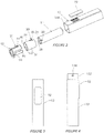
- Figure 2 shows an exploded view of the dispensing device 10 from an angle opposite to that of Figure 1 such that certain features not visible in Figure 1 can be seen.
- the dispensing head region 17 has rounded edges 22 and defines a flat face 24 having a dispensing opening 26.
- the dispensing opening 26 allows for the perfume to be displaced from the pump means 140 housed inside the dispensing container 14 to an outside environment.
- the top operative end region 16 has a protrusion 28 located along the cylindrical body 20.
- the case 12 houses a transmission element 30 which is rotatably mounted with respect to the case 12, and a blocking means 32.
- the transmission element 30 typically comprises, but is not limited to, being manufactured from a plastics material to be a hollow cylinder body 34 between two opposing open ends 36, 38, each open end 36, 38 having non-rounded right angled edges 39, 41 with respect to the body 34.
- the body 34 of the transmission element 30 defines a helical groove 40.
- the dispensing container 14 matingly engages the transmission element 30 (as shown in Figures 8A, 8B and 9A to 9C ) such that the protrusion 28 mates with the helical groove 40.
- the helical groove 40 facilitates sliding movement of the protrusion 28 which is matingly accommodated by the helical groove 40.
- the mating action, in operation, by and between the protrusion 28 and the helical groove 40 forms a linking means which facilitates translational movement of the dispensing container 14 between a retractable position (shown in Figures 1A , 3 , 5A and 5B ) and an extended position (shown in Figure 4 , 6A , 6B and 7 ).
- Figure 1A shows a perspective view of a dispensing device 10 in the extended position and Figure 4 shows a side view of the dispensing device 10 in the extended position.
- Figure 3 shows a front view of the dispensing device in the retracted position.
- Figure 1 shows the case 12 having an open end region 144 to receive an actuation button 132 having side walls 134, a flat top wall 136 and a perfume opening 138.
- actuation button 132 having side walls 134, a flat top wall 136 and a perfume opening 138.
- Figures 13A-C Detailed views of the actuation button 132 are shown in Figures 13A-C .
- the bottom end 133 of the button 132 abuts against the surface 54 which forms part of the blocking means 32 when actuated.
- the perfume opening 138 is in liquid communication with the perfume inside the container 14 via a pump means 140.
- the actuation button 132 is dimensioned in such a fashion as to be accommodatable within the case 12.
- the button 132 is received by the case 12 such that the side walls 134 are spaced from the inner side walls 142 of the case 12 to allow for translational movement, making only the flat top wall 136 visible to the eye of a user.
- the flat top wall 136 is flush with the open end region 144 of the case such that the device 10 aesthetically appears to be a three dimensional rectangle as shown in Figure 3 .
- the button 132 is displaced from inside the case 12 to at least partially extend out of the case 12 into an outside environment.
- the button now extended can now be depressed by a user without causing the device to revert back to a retracted position. Depression causes the button 132 to abut against the surface 54. Depression of the button 132 actuates the pump means 140 resulting in perfume being expelled from the pump means 140, which is housed inside the container 14, and out through the perfume opening 138, which will be further explained in detail below.
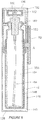
- Figure 5 , 6A and 6B show a particular embodiment of the invention wherein the pump means 140 has a flat bottomed 143 cylindrical body 148 which houses the perfume.
- Figure 5 shows a sectional side view of the dispensing device 10 in the retracted position
- Figure 6A shows a sectional front view of the dispensing device 10 in the extended position
- Figure 6B shows a sectional side view of the dispensing device 10 in the extended position.
- the top end 150 of the body 148 is tapered and screw threaded (not shown).
- a nozzle 152 having a complementary screw thread (not shown) is received by the top end 150 and secured in place.
- a tube member 158 Attached to the nozzle 152, and depending from it down into the space 154 defined by the inner walls 156 of the cylindrical body 148, is a tube member 158.
- the tube member 158 operatively is at least partially immersed in liquid perfume when the device 10 is assembled and ready for use.
- Attached to an open end 160 of the nozzle 152 is a dispensing guide head 162 which acts to guide perfume being expelled from inside the space 154 of the body 148 through the open end 160 of the nozzle 152 and out the perfume opening 138 of the actuation button 132.
- the pump means 140 causes perfume to move up the tube member 158, pass through the nozzle 152, pass out through the open end of the nozzle 160, pass into and through the dispensing guide head 162, and finally into and through the perfume opening 138 of the button 132 into an/or on a location in an outside environment predetermined by a user.
- the blocking means 32 is typically manufactured from, but not limited to, a plastics material to be a hollow cylinder 42 between two opposing open ends 44, 46, each end defining openings 50, 48.
- End 44 is formed by recurvature of the plastics material forming the hollow cylinder 42 to form a recurved lipped end 44.
- End 46 being flat faced, adjoins to a generally square shaped plate 52, which plate 52 having an opening 53 at its centre such that the opening 53 is continuous with the opening 48 defined by open end 46.
- the plate 52 extends in dimension beyond the diameter of the hollow cylinder 42.
- the plate 52 has two opposing surfaces 54, 56 and an intermediate portion 58 in between.
- the four corners defining the general square of the plate 52 are manufactured to define four individual seats, three of which are shown as 60, 62 and 64.
- Two of these seats 60 and 62 are formed by having a base, being a section of the surface 54, and a partially surrounding concave wall 63, being a sectional region of the intermediate portion 58, as shown in Figure 8A, 8B , 9A, 9B and 9C .
- the other two seats are formed by having a base, being a section of the surface 56, and a partially surrounding concave wall, being a sectional region of the intermediate portion 58, and one of these seats is indicated as seat 64, whilst the remaining seat is not shown in the figures.
- Each individual seat 60, 62, 64 engages a complementary engaging means 91 (shown in Figure 12 ) located on the inner wall 93 of the case 12 such that operative engagement prevents any further translation of the dispensing container 14 beyond a certain predetermined position, when the device 10 is actuated by a user from a retracted position to an extended position.
- a complementary engaging means 91 shown in Figure 12
- Figure 8A and 8B shows that the intermediate portion 58 of the plate 52 defines a lip 68, which lip 68 defines a recessed groove 72. Neither the recurved lipped end 44 nor the flat faced end 46 forms a continuous edge.
- the hollow cylinder 42 defines a slot 74 extending from the surface 56 down the wall 82 of the cylinder 42 to a predetermined end 84 thereby forming a rectangular slot 74.
- the hollow cylinder 42 further defines two slots 78, 80 in the wall 82 of the hollow cylinder 42 extending from the recurved lipped end 44 through to the flat faced end 46 to form a rounded end region 88, 90 off centre relative to the central axis 97 of the slots 78 and 80 at the operative upper end of the blocking means 32.
- the flat faced end 46 abuts the surface 56 of the plate 52 to form the composite blocking means 32. Furthermore, the lip 68 and groove 72 of the intermediate portion 58 operatively engage a securing means in the form of a protrusion 95 located on the inner wall 93 of the case to further prevent any unwanted translation of the dispensing container 14 beyond a certain predetermined position (as shown in Figure 10A ).
- the blocking means 32 matingly engages the transmission element 30 (as shown in Figure 8 and 9 ) such that the transmission element 30 is accommodated by the blocking means 32 and secured in place by and between cooperation between the recurved lipped end 44 and the non-rounded right angled edge 39 of the transmission element 30.
- the transmission element 30 is further secured in place by abutment against the surface 56 of the plate 52.
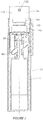
- In the secured position at least one slot 78 or 80 is adjacent the helical groove 40 such that the protrusion 28 of the dispensing container 14 can be operatively received by a portion of the at least one slot 78 or 80 and by a portion of the helical groove 40 concomitantly (as shown in Figure 7 and 11 ).
- the container 14 can then move from a retracted position, Figure 5 , to an intermediate position, Figure 9B , and finally to a secured extended position, Figure 6A, 6B , 7 and 9C .
- Actuation of the dispensing device 10 such that the dispensing container 14 is in the extended position ready for use by a user is caused by manual manipulation by said user of an actuating element 92.
- the actuating element 92 is typically a flat rectangular plate and cooperates with the transmission element 30 to cause movement of the dispensing container 14 as will be described in detail below.
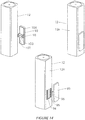
- Detailed views showing cooperation by and between the actuation element 92 and the remainder of the components of the dispensing device 10 are shown in Figures 6B , 10A , 10B , 12 and 14 .
- the wall of the case 12 defines three slots 94, 95, 96, each slot operatively accommodating a protrusion 98, 100, 102 which protrudes from a bottom surface 104 of the actuating element 92.
- Figure 12 shows the two side protrusions 98, 102 defining tapered ends to facilitate guiding the actuation element 92 to engage the dispensing container 14 when the dispensing device 10 is assembled, and further, each side protrusion 98, 102 has a recessed engaging means 106, 108.
- the wall of the case 12 which defines the two side slots 94, 96 is so shaped to provide male protrusions 110, 112 when viewed in plan view shown in Figure 12 .
- Each male protrusion 110, 112 of the wall of the case 12 seats against the recessed engaging means 106, 108 to operatively secure in place the actuation element 92 to the case 12.
- the securement of the actuation element 92 is such that the element 92 cannot easily disengage from the case 12, but is such that it allows translational movement of the element 92 relative the outer walls of the case 12.
- Figure 12 shows a sectional plan view of how the actuation element 92 engages the remainder of the dispensing device's 10 components and shows the central protrusion 100 of the actuation element 92 matingly engaging the central slot 95 defined by the wall of the case 12.
- the central protrusion 100 comprises two side walls 114, 116 each side wall having a shoulder 118, 120 causing a slight variation in dimensions to the central protrusion 100.
- the central protrusion 100 has at its front protruding end a concave face 122 for complementary abutment against the convex outer wall 124 of the dispensing container.
- the smaller dimensions of the front region of the central protrusion 100 relative to the back region allow for facilitating the ease of assembly of the dispensing device 10 as the smaller dimensions act as a guide into the slot 95, therein making the assembly of the device 10 easier.
- the shoulders 118, 120 then act, in the assembled form, to secure engagement of the actuation element 30 to the case 12.
- the central protrusion 100 now engages a portion of the helical groove 40 and a portion of rectangular slot 74 of the blocking means 32 concomitantly such that the concave face 122 of the central protrusion 100 abuts the complementary shaped outer wall 124 of the dispensing container as mentioned above.
- Actuation of the actuating element 92 by a user causes translational movement of the actuation element 92 along the outer wall 126 of the case. Since the central protrusion 100 is matingly engaged with rectangular slot 74 and the helical groove 40, the actuation of the element 92 which causes the translational movement of the element 92 relative the outer wall of the case 126 in turn causes concerted rotational movement of the transmission element 30 which in turn causes translational movement of the dispensing container 14 between a retracted and an extended position.
- the translational movement between the retracted and extended positions is delimited by the base 128 of the case 12 and the secured position of the blocking means 32.
- the central protrusion 100 slidingly moves along rectangular slot 74 until it abuts against the terminating end 84 of the slot.
- Such terminating end 84 prevents further movement of the central protrusion 100 and therein prevents further displacement of the container 14 from a retracted position to an extended position.
- Figure 11 shows a detailed view corresponding to area C of Figure 7 and is a sectional side view of the engagement of the protrusion 28 located on the dispensing container 14 in a secured position such that the dispensing device 10 is in the extended position.
- actuation of the actuating element 92 causes translational movement which in turn actuates rotational movement and causes displacement of the dispensing container 14 between a retracted and extended position.
- This actuation of the actuating element 92 causes the protrusion 28 of the dispensing container 14 which is engaged in either one of slots 78 or 80 to slidingly traverse along the slot 78 or 80 until the protrusion 28 securingly engages the rounded end region 88 or 90 which then prevents any further movement and secures the dispensing device 10 in an operative condition being in the extended position.
- the dispensing container 14 comprises two protrusions 28 located opposite each other such that one protrusion 28 engages slot 78 and the other engages slot 80.
- one protrusion 28 will securingly engage rounded end region 88 and the other will securingly engage rounded end region 90.
- the device 10 is more robust and less likely to fail in its operation. This embodiment is not shown in the figures.
- the device 10 could come in a range of different shapes and sizes and may be made from a range of suitable materials.
- the above description of preferred embodiments should be understood as not being limiting to the scope of the invention.
- the device 10 alleviates at least one of the problems experienced in the prior art by enabling a user to, through the use of one hand, actuate the device 10 and cause there to be expelled into an outside environment an amount of a cosmetic product, preferably perfume.
Landscapes
- Containers And Packaging Bodies Having A Special Means To Remove Contents (AREA)
Claims (13)
- Spendervorrichtung (10) zum Spenden eines kosmetischen Produkts, wobei die Spendervorrichtung umfasst:ein Gehäuse (12);einen Spenderbehälter (14), der einen Hohlraum zum Enthalten des kosmetischen Produkts aufweist, und einen Spenderkopf, der eine Spenderöffnung (26) aufweist, wobei der Spenderbehälter innerhalb des Gehäuses zwischen einer zurückgezogenen Position, in der die Spenderöffnung innerhalb des Gehäuses untergebracht ist, und einer ausgefahrenen Position, in der die Spenderöffnung aus dem Gehäuse herausragt, verschiebbar ist; undein Übertragungselement (30), das drehbar in Bezug auf das Gehäuse montiert und innerhalb des Gehäuses untergebracht ist, wobei eine Drehbewegung des Übertragungselements eine Translationsbewegung des Spenderbehälters in Bezug auf das Gehäuse bewirkt,dadurch gekennzeichnet, dass die Vorrichtung weiter ein Betätigungselement (92) umfasst, das in Bezug auf das Gehäuse verschiebbar und an einer Außenwand des Gehäuses befestigt ist, wobei das Betätigungselement mit dem Übertragungselement durch erste Verbindungsmittel zusammenwirkt, die zum Umwandeln der Translationsbewegung des Betätigungselements entlang der Außenwand des Gehäuses in die Drehbewegung des Übertragungselements zum Bewegen des Spenderbehälters zwischen der eingefahrenen Position und der ausgefahrenen Position ausgelegt sind.
- Spendervorrichtung nach Anspruch 1, wobei das kosmetische Produkt in einem Kosmetikbehälter untergebracht ist, wobei der Kosmetikbehälter innerhalb des Hohlraums des Spenderbehälters untergebracht ist, wobei der Kosmetikbehälter in Fluidverbindung mit der Spenderöffnung des Spenderkopfes steht.
- Spendervorrichtung nach Anspruch 1 oder 2, weiter umfassend einen Betätigungskopf, der eine Öffnung in Fluidverbindung mit der Spenderöffnung des Spenderbehälters aufweist, so dass, wenn sich die Spendervorrichtung in der eingefahrenen Position befindet, der Betätigungskopf in dem Gehäuse untergebracht ist, und, wenn sich die Spendervorrichtung in der ausgefahrenen Position befindet, der Betätigungskopf aus dem Gehäuse vorsteht.
- Spendervorrichtung nach einem der Ansprüche 1 bis 3, wobei das Betätigungselement einen ersten Vorsprung umfasst und wobei das Übertragungselement ein Hohlzylinder ist und eine spiralförmige Nut aufweist, in welcher der erste Vorsprung untergebracht ist und in welcher der erste Vorsprung gleitet, wobei der erste Vorsprung und die Nut das erste Verbindungsmittel zwischen dem Betätigungselement und dem Übertragungselement bilden.
- Spendervorrichtung nach Anspruch 4, weiter umfassend ein Blockiermittel zum Begrenzen der Translationsbewegung des Übertragungselements in Bezug auf das Gehäuse, wobei das Blockiermittel in dem Gehäuse untergebracht ist.
- Spendervorrichtung nach Anspruch 5, wobei das Blockiermittel einen zweiten Hohlzylinder umfasst, wobei der zweite Hohlzylinder einen ersten Schlitz und einen zweiten Schlitz definiert, wobei der erste Schlitz rechteckig ist und der zweite Schlitz einen abgerundeten Endbereich außermittig in Bezug auf die Achse des zweiten Schlitzes aufweist.
- Spendervorrichtung nach Anspruch 6, wobei das Übertragungselement zusammenpassend mit dem Blockiermittel in Eingriff steht, so dass das Blockiermittel das Übertragungselement unterbringt.
- Spendervorrichtung nach Anspruch 7, wobei der erste Vorsprung weiter innerhalb des ersten Schlitzes des Blockiermittels untergebracht ist, so dass die Translation des Betätigungselements entlang der Wand des Gehäuses durch die Abmessungen des ersten Schlitzes begrenzt wird.
- Spendervorrichtung nach Anspruch 8, wobei der erste Vorsprung gleichzeitig in den ersten Schlitz und die spiralförmige Nut eingreift.
- Spendervorrichtung nach einem der Ansprüche 6 bis 9, wobei das Blockiermittel ein erstes und ein zweites offenes Ende aufweist, wobei das erste offene Ende an einer Platte befestigt ist, wobei die Platte Befestigungsmittel umfasst, um mit komplementären Befestigungsmitteln, die innerhalb des Gehäuses angeordnet sind, betriebswirksam in Eingriff zu kommen, sodass das Blockiermittel an einer bestimmten Position innerhalb des Gehäuses gesichert ist.
- Spendervorrichtung nach einem der Ansprüche 6 bis 10, wobei das Betätigungselement mit dem Spenderbehälter durch zweite Verbindungsmittel zusammenwirkt, die zum Umwandeln der Drehbewegung des Übertragungselements in eine Translationsbewegung des Spenderbehälters in Bezug auf das Gehäuse ausgelegt sind.
- Spendervorrichtung nach Anspruch 11, wobei der Spenderbehälter einen zweiten Vorsprung umfasst, der von der spiralförmigen Nut untergebracht wird, wobei der zweite Vorsprung und die spiralförmige Nut das zweite Verbindungsmittel zwischen dem Übertragungselement und dem Spenderbehälter bilden.
- Spendervorrichtung nach Anspruch 12, wobei der zweite Vorsprung weiter innerhalb des zweiten Schlitzes des Blockiermittels untergebracht ist, so dass, wenn sich die Spendervorrichtung in der eingefahrenen Position befindet, der zweite Vorsprung in dem zweiten Schlitz untergebracht ist, und, wenn sich die Spendervorrichtung in der ausgefahrenen Position befindet, der zweite Vorsprung innerhalb des abgerundeten Endbereichs außermittig in Bezug auf die Achse des zweiten Schlitzes untergebracht ist, der die Translationsbewegung des Übertragungselements begrenzt und die Spendervorrichtung in der ausgefahrenen Position sichert.
Applications Claiming Priority (1)
| Application Number | Priority Date | Filing Date | Title |
|---|---|---|---|
| US201161484974P | 2011-05-11 | 2011-05-11 |
Publications (3)
| Publication Number | Publication Date |
|---|---|
| EP2522247A2 EP2522247A2 (de) | 2012-11-14 |
| EP2522247A3 EP2522247A3 (de) | 2017-12-06 |
| EP2522247B1 true EP2522247B1 (de) | 2018-09-12 |
Family
ID=46084914
Family Applications (1)
| Application Number | Title | Priority Date | Filing Date |
|---|---|---|---|
| EP12167748.8A Active EP2522247B1 (de) | 2011-05-11 | 2012-05-11 | Spendervorrichtung |
Country Status (1)
| Country | Link |
|---|---|
| EP (1) | EP2522247B1 (de) |
Cited By (2)
| Publication number | Priority date | Publication date | Assignee | Title |
|---|---|---|---|---|
| WO2022000610A1 (zh) * | 2020-07-02 | 2022-01-06 | 安徽亦宣金属科技有限公司 | 全金属化妆管 |
| WO2022256888A1 (pt) * | 2021-06-08 | 2022-12-15 | Eric Zembrod | Estojo para uma embalagem/refil |
Families Citing this family (1)
| Publication number | Priority date | Publication date | Assignee | Title |
|---|---|---|---|---|
| CN110159776B (zh) * | 2019-05-13 | 2024-12-27 | 广东爱车小屋电子商务科技有限公司 | 出风调节机构、香薰容器及香薰 |
Family Cites Families (2)
| Publication number | Priority date | Publication date | Assignee | Title |
|---|---|---|---|---|
| FR2686002B3 (fr) * | 1992-01-15 | 1993-11-26 | Chen Sin Hsiung | Recipient de parfum retractable. |
| US20100054842A1 (en) * | 2008-09-02 | 2010-03-04 | Devito Ralph | Slide Up Lipstick Dispenser |
-
2012
- 2012-05-11 EP EP12167748.8A patent/EP2522247B1/de active Active
Non-Patent Citations (1)
| Title |
|---|
| None * |
Cited By (2)
| Publication number | Priority date | Publication date | Assignee | Title |
|---|---|---|---|---|
| WO2022000610A1 (zh) * | 2020-07-02 | 2022-01-06 | 安徽亦宣金属科技有限公司 | 全金属化妆管 |
| WO2022256888A1 (pt) * | 2021-06-08 | 2022-12-15 | Eric Zembrod | Estojo para uma embalagem/refil |
Also Published As
| Publication number | Publication date |
|---|---|
| EP2522247A2 (de) | 2012-11-14 |
| EP2522247A3 (de) | 2017-12-06 |
Similar Documents
| Publication | Publication Date | Title |
|---|---|---|
| US10858170B2 (en) | Dual dispensing cosmetic container | |
| JP4679142B2 (ja) | ロック可能な分配ヘッド | |
| US9347811B2 (en) | Dropper assembly | |
| EP2767485B1 (de) | Kindersichere Mengendosierungsausgabeeinheit | |
| EP2905571B1 (de) | Gehäuse mit Flüssigkeitsspender | |
| KR101631827B1 (ko) | 펌프 타입 컴팩트 용기 | |
| US8714412B2 (en) | Fluid dispenser having a retractable head | |
| US8777061B1 (en) | Safety closure for container | |
| EP0987189A2 (de) | Zusammenlegbare Deckelvorrichtung zur Abschirmung eines Pumpenantriebs und damit ausgestatteter Flüssigkeitsabgabebehälter | |
| US4848595A (en) | Product dispenser with shiftable closure blade | |
| US6983865B2 (en) | Fluid dispenser device | |
| JP7678156B2 (ja) | ポンプを備えた補充物のための包装デバイス | |
| CN104768656A (zh) | 流体产品分配器 | |
| EP3203872B1 (de) | Vorrichtung zur verpackung und verwendung mittels einer pipette | |
| EP3395712A1 (de) | Flüssigkeitsausstossbehälter | |
| EP2522247A2 (de) | Spendervorrichtung | |
| WO2008150810A1 (en) | Dispenser and methods of using the same | |
| EP3492172A1 (de) | Tropfer | |
| US10252284B2 (en) | Foam pump actuator with folding nozzle suitable for e-commerce | |
| EP0572903A1 (de) | Betätiger für eine Pumpe | |
| JP7488168B2 (ja) | 棒状化粧料容器 | |
| US8887950B2 (en) | Case for cosmetic or body hygiene product having a retractable hinge | |
| EP3295824B1 (de) | Kosmetikbehälter | |
| CA3127016C (en) | Device for holding and dispensing viscous material | |
| US7878374B2 (en) | Fluid product dispenser |
Legal Events
| Date | Code | Title | Description |
|---|---|---|---|
| PUAI | Public reference made under article 153(3) epc to a published international application that has entered the european phase |
Free format text: ORIGINAL CODE: 0009012 |
|
| AK | Designated contracting states |
Kind code of ref document: A2 Designated state(s): AL AT BE BG CH CY CZ DE DK EE ES FI FR GB GR HR HU IE IS IT LI LT LU LV MC MK MT NL NO PL PT RO RS SE SI SK SM TR |
|
| AX | Request for extension of the european patent |
Extension state: BA ME |
|
| PUAL | Search report despatched |
Free format text: ORIGINAL CODE: 0009013 |
|
| AK | Designated contracting states |
Kind code of ref document: A3 Designated state(s): AL AT BE BG CH CY CZ DE DK EE ES FI FR GB GR HR HU IE IS IT LI LT LU LV MC MK MT NL NO PL PT RO RS SE SI SK SM TR |
|
| AX | Request for extension of the european patent |
Extension state: BA ME |
|
| RIC1 | Information provided on ipc code assigned before grant |
Ipc: A45D 34/00 20060101AFI20171031BHEP Ipc: A45D 40/02 20060101ALN20171031BHEP Ipc: A45D 34/02 20060101ALN20171031BHEP Ipc: A45D 40/06 20060101ALN20171031BHEP |
|
| STAA | Information on the status of an ep patent application or granted ep patent |
Free format text: STATUS: REQUEST FOR EXAMINATION WAS MADE |
|
| 17P | Request for examination filed |
Effective date: 20180205 |
|
| RBV | Designated contracting states (corrected) |
Designated state(s): AL AT BE BG CH CY CZ DE DK EE ES FI FR GB GR HR HU IE IS IT LI LT LU LV MC MK MT NL NO PL PT RO RS SE SI SK SM TR |
|
| GRAP | Despatch of communication of intention to grant a patent |
Free format text: ORIGINAL CODE: EPIDOSNIGR1 |
|
| STAA | Information on the status of an ep patent application or granted ep patent |
Free format text: STATUS: GRANT OF PATENT IS INTENDED |
|
| RIC1 | Information provided on ipc code assigned before grant |
Ipc: A45D 34/02 20060101ALN20180302BHEP Ipc: A45D 40/06 20060101ALN20180302BHEP Ipc: A45D 34/00 20060101AFI20180302BHEP Ipc: A45D 40/02 20060101ALN20180302BHEP |
|
| INTG | Intention to grant announced |
Effective date: 20180411 |
|
| GRAS | Grant fee paid |
Free format text: ORIGINAL CODE: EPIDOSNIGR3 |
|
| GRAA | (expected) grant |
Free format text: ORIGINAL CODE: 0009210 |
|
| STAA | Information on the status of an ep patent application or granted ep patent |
Free format text: STATUS: THE PATENT HAS BEEN GRANTED |
|
| AK | Designated contracting states |
Kind code of ref document: B1 Designated state(s): AL AT BE BG CH CY CZ DE DK EE ES FI FR GB GR HR HU IE IS IT LI LT LU LV MC MK MT NL NO PL PT RO RS SE SI SK SM TR |
|
| REG | Reference to a national code |
Ref country code: GB Ref legal event code: FG4D |
|
| REG | Reference to a national code |
Ref country code: CH Ref legal event code: EP |
|
| REG | Reference to a national code |
Ref country code: IE Ref legal event code: FG4D |
|
| REG | Reference to a national code |
Ref country code: DE Ref legal event code: R096 Ref document number: 602012050892 Country of ref document: DE |
|
| REG | Reference to a national code |
Ref country code: AT Ref legal event code: REF Ref document number: 1039559 Country of ref document: AT Kind code of ref document: T Effective date: 20181015 |
|
| REG | Reference to a national code |
Ref country code: NL Ref legal event code: MP Effective date: 20180912 |
|
| REG | Reference to a national code |
Ref country code: LT Ref legal event code: MG4D |
|
| PG25 | Lapsed in a contracting state [announced via postgrant information from national office to epo] |
Ref country code: NO Free format text: LAPSE BECAUSE OF FAILURE TO SUBMIT A TRANSLATION OF THE DESCRIPTION OR TO PAY THE FEE WITHIN THE PRESCRIBED TIME-LIMIT Effective date: 20181212 Ref country code: LT Free format text: LAPSE BECAUSE OF FAILURE TO SUBMIT A TRANSLATION OF THE DESCRIPTION OR TO PAY THE FEE WITHIN THE PRESCRIBED TIME-LIMIT Effective date: 20180912 Ref country code: GR Free format text: LAPSE BECAUSE OF FAILURE TO SUBMIT A TRANSLATION OF THE DESCRIPTION OR TO PAY THE FEE WITHIN THE PRESCRIBED TIME-LIMIT Effective date: 20181213 Ref country code: RS Free format text: LAPSE BECAUSE OF FAILURE TO SUBMIT A TRANSLATION OF THE DESCRIPTION OR TO PAY THE FEE WITHIN THE PRESCRIBED TIME-LIMIT Effective date: 20180912 Ref country code: BG Free format text: LAPSE BECAUSE OF FAILURE TO SUBMIT A TRANSLATION OF THE DESCRIPTION OR TO PAY THE FEE WITHIN THE PRESCRIBED TIME-LIMIT Effective date: 20181212 Ref country code: FI Free format text: LAPSE BECAUSE OF FAILURE TO SUBMIT A TRANSLATION OF THE DESCRIPTION OR TO PAY THE FEE WITHIN THE PRESCRIBED TIME-LIMIT Effective date: 20180912 Ref country code: SE Free format text: LAPSE BECAUSE OF FAILURE TO SUBMIT A TRANSLATION OF THE DESCRIPTION OR TO PAY THE FEE WITHIN THE PRESCRIBED TIME-LIMIT Effective date: 20180912 |
|
| PG25 | Lapsed in a contracting state [announced via postgrant information from national office to epo] |
Ref country code: LV Free format text: LAPSE BECAUSE OF FAILURE TO SUBMIT A TRANSLATION OF THE DESCRIPTION OR TO PAY THE FEE WITHIN THE PRESCRIBED TIME-LIMIT Effective date: 20180912 Ref country code: AL Free format text: LAPSE BECAUSE OF FAILURE TO SUBMIT A TRANSLATION OF THE DESCRIPTION OR TO PAY THE FEE WITHIN THE PRESCRIBED TIME-LIMIT Effective date: 20180912 Ref country code: HR Free format text: LAPSE BECAUSE OF FAILURE TO SUBMIT A TRANSLATION OF THE DESCRIPTION OR TO PAY THE FEE WITHIN THE PRESCRIBED TIME-LIMIT Effective date: 20180912 |
|
| REG | Reference to a national code |
Ref country code: AT Ref legal event code: MK05 Ref document number: 1039559 Country of ref document: AT Kind code of ref document: T Effective date: 20180912 |
|
| PG25 | Lapsed in a contracting state [announced via postgrant information from national office to epo] |
Ref country code: IT Free format text: LAPSE BECAUSE OF FAILURE TO SUBMIT A TRANSLATION OF THE DESCRIPTION OR TO PAY THE FEE WITHIN THE PRESCRIBED TIME-LIMIT Effective date: 20180912 Ref country code: IS Free format text: LAPSE BECAUSE OF FAILURE TO SUBMIT A TRANSLATION OF THE DESCRIPTION OR TO PAY THE FEE WITHIN THE PRESCRIBED TIME-LIMIT Effective date: 20190112 Ref country code: ES Free format text: LAPSE BECAUSE OF FAILURE TO SUBMIT A TRANSLATION OF THE DESCRIPTION OR TO PAY THE FEE WITHIN THE PRESCRIBED TIME-LIMIT Effective date: 20180912 Ref country code: AT Free format text: LAPSE BECAUSE OF FAILURE TO SUBMIT A TRANSLATION OF THE DESCRIPTION OR TO PAY THE FEE WITHIN THE PRESCRIBED TIME-LIMIT Effective date: 20180912 Ref country code: PL Free format text: LAPSE BECAUSE OF FAILURE TO SUBMIT A TRANSLATION OF THE DESCRIPTION OR TO PAY THE FEE WITHIN THE PRESCRIBED TIME-LIMIT Effective date: 20180912 Ref country code: EE Free format text: LAPSE BECAUSE OF FAILURE TO SUBMIT A TRANSLATION OF THE DESCRIPTION OR TO PAY THE FEE WITHIN THE PRESCRIBED TIME-LIMIT Effective date: 20180912 Ref country code: NL Free format text: LAPSE BECAUSE OF FAILURE TO SUBMIT A TRANSLATION OF THE DESCRIPTION OR TO PAY THE FEE WITHIN THE PRESCRIBED TIME-LIMIT Effective date: 20180912 Ref country code: CZ Free format text: LAPSE BECAUSE OF FAILURE TO SUBMIT A TRANSLATION OF THE DESCRIPTION OR TO PAY THE FEE WITHIN THE PRESCRIBED TIME-LIMIT Effective date: 20180912 Ref country code: RO Free format text: LAPSE BECAUSE OF FAILURE TO SUBMIT A TRANSLATION OF THE DESCRIPTION OR TO PAY THE FEE WITHIN THE PRESCRIBED TIME-LIMIT Effective date: 20180912 |
|
| PG25 | Lapsed in a contracting state [announced via postgrant information from national office to epo] |
Ref country code: SM Free format text: LAPSE BECAUSE OF FAILURE TO SUBMIT A TRANSLATION OF THE DESCRIPTION OR TO PAY THE FEE WITHIN THE PRESCRIBED TIME-LIMIT Effective date: 20180912 Ref country code: PT Free format text: LAPSE BECAUSE OF FAILURE TO SUBMIT A TRANSLATION OF THE DESCRIPTION OR TO PAY THE FEE WITHIN THE PRESCRIBED TIME-LIMIT Effective date: 20190112 Ref country code: SK Free format text: LAPSE BECAUSE OF FAILURE TO SUBMIT A TRANSLATION OF THE DESCRIPTION OR TO PAY THE FEE WITHIN THE PRESCRIBED TIME-LIMIT Effective date: 20180912 |
|
| REG | Reference to a national code |
Ref country code: DE Ref legal event code: R097 Ref document number: 602012050892 Country of ref document: DE |
|
| PLBE | No opposition filed within time limit |
Free format text: ORIGINAL CODE: 0009261 |
|
| STAA | Information on the status of an ep patent application or granted ep patent |
Free format text: STATUS: NO OPPOSITION FILED WITHIN TIME LIMIT |
|
| PG25 | Lapsed in a contracting state [announced via postgrant information from national office to epo] |
Ref country code: DK Free format text: LAPSE BECAUSE OF FAILURE TO SUBMIT A TRANSLATION OF THE DESCRIPTION OR TO PAY THE FEE WITHIN THE PRESCRIBED TIME-LIMIT Effective date: 20180912 |
|
| 26N | No opposition filed |
Effective date: 20190613 |
|
| PG25 | Lapsed in a contracting state [announced via postgrant information from national office to epo] |
Ref country code: SI Free format text: LAPSE BECAUSE OF FAILURE TO SUBMIT A TRANSLATION OF THE DESCRIPTION OR TO PAY THE FEE WITHIN THE PRESCRIBED TIME-LIMIT Effective date: 20180912 |
|
| REG | Reference to a national code |
Ref country code: DE Ref legal event code: R119 Ref document number: 602012050892 Country of ref document: DE |
|
| REG | Reference to a national code |
Ref country code: CH Ref legal event code: PL |
|
| GBPC | Gb: european patent ceased through non-payment of renewal fee |
Effective date: 20190511 |
|
| PG25 | Lapsed in a contracting state [announced via postgrant information from national office to epo] |
Ref country code: CH Free format text: LAPSE BECAUSE OF NON-PAYMENT OF DUE FEES Effective date: 20190531 Ref country code: LI Free format text: LAPSE BECAUSE OF NON-PAYMENT OF DUE FEES Effective date: 20190531 Ref country code: MC Free format text: LAPSE BECAUSE OF FAILURE TO SUBMIT A TRANSLATION OF THE DESCRIPTION OR TO PAY THE FEE WITHIN THE PRESCRIBED TIME-LIMIT Effective date: 20180912 |
|
| REG | Reference to a national code |
Ref country code: BE Ref legal event code: MM Effective date: 20190531 |
|
| PG25 | Lapsed in a contracting state [announced via postgrant information from national office to epo] |
Ref country code: LU Free format text: LAPSE BECAUSE OF NON-PAYMENT OF DUE FEES Effective date: 20190511 |
|
| PG25 | Lapsed in a contracting state [announced via postgrant information from national office to epo] |
Ref country code: TR Free format text: LAPSE BECAUSE OF FAILURE TO SUBMIT A TRANSLATION OF THE DESCRIPTION OR TO PAY THE FEE WITHIN THE PRESCRIBED TIME-LIMIT Effective date: 20180912 |
|
| PG25 | Lapsed in a contracting state [announced via postgrant information from national office to epo] |
Ref country code: DE Free format text: LAPSE BECAUSE OF NON-PAYMENT OF DUE FEES Effective date: 20191203 Ref country code: GB Free format text: LAPSE BECAUSE OF NON-PAYMENT OF DUE FEES Effective date: 20190511 Ref country code: IE Free format text: LAPSE BECAUSE OF NON-PAYMENT OF DUE FEES Effective date: 20190511 |
|
| PG25 | Lapsed in a contracting state [announced via postgrant information from national office to epo] |
Ref country code: BE Free format text: LAPSE BECAUSE OF NON-PAYMENT OF DUE FEES Effective date: 20190531 |
|
| PG25 | Lapsed in a contracting state [announced via postgrant information from national office to epo] |
Ref country code: CY Free format text: LAPSE BECAUSE OF FAILURE TO SUBMIT A TRANSLATION OF THE DESCRIPTION OR TO PAY THE FEE WITHIN THE PRESCRIBED TIME-LIMIT Effective date: 20180912 |
|
| PG25 | Lapsed in a contracting state [announced via postgrant information from national office to epo] |
Ref country code: MT Free format text: LAPSE BECAUSE OF FAILURE TO SUBMIT A TRANSLATION OF THE DESCRIPTION OR TO PAY THE FEE WITHIN THE PRESCRIBED TIME-LIMIT Effective date: 20180912 Ref country code: HU Free format text: LAPSE BECAUSE OF FAILURE TO SUBMIT A TRANSLATION OF THE DESCRIPTION OR TO PAY THE FEE WITHIN THE PRESCRIBED TIME-LIMIT; INVALID AB INITIO Effective date: 20120511 |
|
| PG25 | Lapsed in a contracting state [announced via postgrant information from national office to epo] |
Ref country code: MK Free format text: LAPSE BECAUSE OF FAILURE TO SUBMIT A TRANSLATION OF THE DESCRIPTION OR TO PAY THE FEE WITHIN THE PRESCRIBED TIME-LIMIT Effective date: 20180912 |
|
| P01 | Opt-out of the competence of the unified patent court (upc) registered |
Effective date: 20230417 |
|
| PGFP | Annual fee paid to national office [announced via postgrant information from national office to epo] |
Ref country code: FR Payment date: 20250530 Year of fee payment: 14 |