EP2522435B1 - Dispositif de Pulvérisation rotatif - Google Patents
Dispositif de Pulvérisation rotatif Download PDFInfo
- Publication number
- EP2522435B1 EP2522435B1 EP11172153.6A EP11172153A EP2522435B1 EP 2522435 B1 EP2522435 B1 EP 2522435B1 EP 11172153 A EP11172153 A EP 11172153A EP 2522435 B1 EP2522435 B1 EP 2522435B1
- Authority
- EP
- European Patent Office
- Prior art keywords
- fluid
- tube
- rotary
- spraying device
- fluid tube
- Prior art date
- Legal status (The legal status is an assumption and is not a legal conclusion. Google has not performed a legal analysis and makes no representation as to the accuracy of the status listed.)
- Active
Links
Images



Classifications
-
- B—PERFORMING OPERATIONS; TRANSPORTING
- B05—SPRAYING OR ATOMISING IN GENERAL; APPLYING FLUENT MATERIALS TO SURFACES, IN GENERAL
- B05B—SPRAYING APPARATUS; ATOMISING APPARATUS; NOZZLES
- B05B3/00—Spraying or sprinkling apparatus with moving outlet elements or moving deflecting elements
- B05B3/02—Spraying or sprinkling apparatus with moving outlet elements or moving deflecting elements with rotating elements
- B05B3/04—Spraying or sprinkling apparatus with moving outlet elements or moving deflecting elements with rotating elements driven by the liquid or other fluent material discharged, e.g. the liquid actuating a motor before passing to the outlet
-
- B—PERFORMING OPERATIONS; TRANSPORTING
- B05—SPRAYING OR ATOMISING IN GENERAL; APPLYING FLUENT MATERIALS TO SURFACES, IN GENERAL
- B05B—SPRAYING APPARATUS; ATOMISING APPARATUS; NOZZLES
- B05B15/00—Details of spraying plant or spraying apparatus not otherwise provided for; Accessories
- B05B15/30—Dip tubes
- B05B15/33—Weighted
-
- B—PERFORMING OPERATIONS; TRANSPORTING
- B05—SPRAYING OR ATOMISING IN GENERAL; APPLYING FLUENT MATERIALS TO SURFACES, IN GENERAL
- B05B—SPRAYING APPARATUS; ATOMISING APPARATUS; NOZZLES
- B05B7/00—Spraying apparatus for discharge of liquids or other fluent materials from two or more sources, e.g. of liquid and air, of powder and gas
- B05B7/24—Spraying apparatus for discharge of liquids or other fluent materials from two or more sources, e.g. of liquid and air, of powder and gas with means, e.g. a container, for supplying liquid or other fluent material to a discharge device
- B05B7/2402—Apparatus to be carried on or by a person, e.g. by hand; Apparatus comprising containers fixed to the discharge device
- B05B7/2405—Apparatus to be carried on or by a person, e.g. by hand; Apparatus comprising containers fixed to the discharge device using an atomising fluid as carrying fluid for feeding, e.g. by suction or pressure, a carried liquid from the container to the nozzle
- B05B7/2435—Apparatus to be carried on or by a person, e.g. by hand; Apparatus comprising containers fixed to the discharge device using an atomising fluid as carrying fluid for feeding, e.g. by suction or pressure, a carried liquid from the container to the nozzle the carried liquid and the main stream of atomising fluid being brought together by parallel conduits placed one inside the other
-
- B—PERFORMING OPERATIONS; TRANSPORTING
- B05—SPRAYING OR ATOMISING IN GENERAL; APPLYING FLUENT MATERIALS TO SURFACES, IN GENERAL
- B05B—SPRAYING APPARATUS; ATOMISING APPARATUS; NOZZLES
- B05B3/00—Spraying or sprinkling apparatus with moving outlet elements or moving deflecting elements
- B05B3/02—Spraying or sprinkling apparatus with moving outlet elements or moving deflecting elements with rotating elements
- B05B3/04—Spraying or sprinkling apparatus with moving outlet elements or moving deflecting elements with rotating elements driven by the liquid or other fluent material discharged, e.g. the liquid actuating a motor before passing to the outlet
- B05B3/0417—Spraying or sprinkling apparatus with moving outlet elements or moving deflecting elements with rotating elements driven by the liquid or other fluent material discharged, e.g. the liquid actuating a motor before passing to the outlet comprising a liquid driven rotor, e.g. a turbine
- B05B3/0429—Spraying or sprinkling apparatus with moving outlet elements or moving deflecting elements with rotating elements driven by the liquid or other fluent material discharged, e.g. the liquid actuating a motor before passing to the outlet comprising a liquid driven rotor, e.g. a turbine the rotating outlet elements being directly attached to the rotor or being an integral part thereof
-
- B—PERFORMING OPERATIONS; TRANSPORTING
- B05—SPRAYING OR ATOMISING IN GENERAL; APPLYING FLUENT MATERIALS TO SURFACES, IN GENERAL
- B05B—SPRAYING APPARATUS; ATOMISING APPARATUS; NOZZLES
- B05B7/00—Spraying apparatus for discharge of liquids or other fluent materials from two or more sources, e.g. of liquid and air, of powder and gas
- B05B7/02—Spray pistols; Apparatus for discharge
- B05B7/06—Spray pistols; Apparatus for discharge with at least one outlet orifice surrounding another approximately in the same plane
- B05B7/062—Spray pistols; Apparatus for discharge with at least one outlet orifice surrounding another approximately in the same plane with only one liquid outlet and at least one gas outlet
- B05B7/066—Spray pistols; Apparatus for discharge with at least one outlet orifice surrounding another approximately in the same plane with only one liquid outlet and at least one gas outlet with an inner liquid outlet surrounded by at least one annular gas outlet
Definitions
- the present invention relates to a spraying gun, and more particularly to a rotary spraying device driven by a rotary means thereof.
- DE 20 2009 013337 and DE 20 2010 010018 refer to fluid spraying devices comprising a rotatable tube.
- spraying guns have been used widely for cleaning dust and dirt from a surface of an object, for watering, for spraying paint, and the like.
- the spraying guns remove dust and dirt by spraying a high pressure fluid, and perform watering and spraying paint with the use of a high pressure fluid mixed with water or other spraying liquid.
- the spraying gun is manufactured to have a spraying tube with a bending shape and a rotating device is provided to couple with the spraying tube of the spraying gun.
- a rotating device When rotating the spraying tube by the rotating device, a mixed fluid of a high pressured gas and a spraying liquid can be sprayed out in e in every direction with the rotation of the spraying tube.
- the rotating device may be a fan having a plurality of fan blades, so as to be rotated by turning, by the high pressured gas introduced into the spraying gun, the fan blades.
- the rotating device may be a motor which is driven by power supplying, so as to make the spraying tube rotating.
- the rotating device which is a fan, is more difficultly in manufacturing and miniaturizing, and is easily damaged and deformed.
- the motor needs power supplying for operation so the rotating device wastes in production cost and power consumption.
- the spraying tube is rotated by a fan or a motor according to a prior art of the spraying gun, so that the spraying gun is difficult in manufacture and costly in production.
- the present invention overcomes the drawbacks of the prior art, and provides a rotary spraying device comprising: a fluid tube provided at one end thereof with a fluid inlet and the other end thereof with a spraying outlet, and a through hole provided on tube wall of the fluid tube; a rotary means, coupled with the fluid tube, provided with a drive wall inclining to a fluid output direction of the through hole and an outflow passage formed at an end of the drive wall, where the drive wall is driven and pushed by a force of fluid output from the through hole via a fluid connection by a flow space; and a conveying tube provided at one end thereof with a fluid container inlet for connecting to a fluid container, and the other end thereof being disposed within the fluid tube to extend to the spraying outlet of the fluid tube.
- the drive wall of the rotary means is formed extending along an involute curve.
- the rotary means is further provided with a plurality of fastening ribs extending toward the fluid tube.
- the rotary means includes a front fastening layer, a back fastening layer, and a flow channel layer disposed therebetween.
- said front fastening layer and said back fastening layer are made of a rigid material and said flow channel layer is made of a plastic material.
- the fluid tube is further provided inside with a splitter for splitting the fluid flowing through the fluid tube into two portion, wherein one portion of the fluid flows toward the spraying outlet of the fluid tube and the other portion of the fluid flows toward the through hole of the fluid tube.
- the conveying tube is further provided inside with a flow rate regulating means including a water stopper and a seal member, the water stopper is formed with a flow hole and the seal member is formed at one end thereof with a sharp section movably disposed in the flow hole of the water stopper.
- the rotary spraying device further comprising a rotation speed adjusting means including a first adjusting member and a second adjusting member, wherein the first adjusting member is connected with the outflow passage of the rotary means and has an outlet surface formed with a plurality of first openings and the second adjusting member has an inlet surface coupled with the outlet surface of the first adjusting member to rotate with first adjusting member, and the inlet surface is formed with a plurality of second openings corresponding to the first openings.
- a rotation speed adjusting means including a first adjusting member and a second adjusting member, wherein the first adjusting member is connected with the outflow passage of the rotary means and has an outlet surface formed with a plurality of first openings and the second adjusting member has an inlet surface coupled with the outlet surface of the first adjusting member to rotate with first adjusting member, and the inlet surface is formed with a plurality of second openings corresponding to the first openings.
- the fluid tube can be rotated without power supplying.
- the rotary means is stronger in structure and is easy in miniaturizing because the drive wall, the outflow passage, the flow space and so on are formed inside the rotary means. Further, the rotary means having such structure can be stable in rotating and rotate uniformly in high speed with low variation, and those effects are good for fluid spraying.
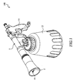
- FIG. 1 is a perspective view illustrating an embodiment according to the present invention
- FIG. 2 is a cross-section view of FIG. 1
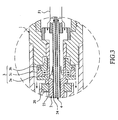
- FIG. 3 is a partial enlarged view of FIG. 2
- a rotary spraying device 100 comprises a body 1 provided at an end thereof with a control handle 11 and a lower portion thereof with a fluid container 12.
- a fluid tube 2 which is provided in the body 1 , is assembled to the body 1 with a bearing 20 , so as to rotate with an axial of the fluid spraying device 100.
- the fluid tube 2 is provided at one end with a fluid inlet 21 extending within the control handle 11.
- the other end of the fluid tube 2 is provided with a spraying outlet 22 extending to an opposite side of the body 1.
- a fluid F1 input from the fluid inlet 21 will be output from the spraying outlet 22.
- a rotary means 3, provided in the body 1, is coupled with the fluid tube 2, so that the fluid tube 2 can be rotated with the rotary means 3 together to process rotary spraying.
- a conveying tube 4 provided in the body 1, is provided at one end with a fluid container inlet 41 connecting with the fluid container 12 and the other end with a contained fluid outlet 42 which is disposed within the fluid tube 2 and extends to the spraying outlet 22 of the fluid tube 2.
- a fluid container inlet 41 connecting with the fluid container 12
- a contained fluid outlet 42 which is disposed within the fluid tube 2 and extends to the spraying outlet 22 of the fluid tube 2.
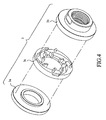
- FIG. 4 is a perspective view illustrating a rotary means
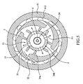
- FIG. 5 is a cross-section view of the rotary means.
- the rotary means 3 in this embodiment includes a front fastening layer 3a, a back fastening layer 3b , and a flow channel layer 3c disposed therebetween.
- the front fastening layer 3a and the back fastening layer 3b have a simple configuration, both of them may be made of a rigid material such as a metal material, an acrylic resin material, or the like.
- the flow channel layer 3c has a complex configuration so it is preferred to be made of a plastic material such as a plastic, a rubber, or the like. By such way in material selection, it makes the rotary means 3 being easy in manufacture.
- the present invention is not limited to this, and the flow channel layer 3c may be made of a rigid material as well.
- the rotary means 3 is coupled with the fluid tube 2.
- a plurality of through holes 23 are provided on tube wall of the fluid tube 2 for connecting with the rotary means 3.
- the fluid tube 2 is also provided inside with a splitter 24.
- the splitter 24, which is a tube in this embodiment, is disposed inside the fluid tube 2 for splitting the fluid tube 2 into two sections, and thus the fluid F1 will be split into two portions when flowing through the splitter 24.
- One portion of the fluid F1 flows to the spraying outlet 22 of the fluid tube 2 through the section adjacent to inside of the splitter 24, and the other portion of the fluid F1 flows to the through holes 23 of the fluid tube 2 through the section adjacent to outside of the splitter 24 and then flows into the rotary means 3 from the through holes 23.
- the rotary means 3 is provided with a drive wall 31 inclining to a fluid output direction of the through hole 23 and an outflow passage 32 formed at an end of the drive wall 31.
- the fluid F1 which flows into the rotary means 3 through the through holes 23, flows through a flow space 33 to push the drive wall 31 and then flows out from the rotary means 3 through the outflow passage 32.
- the drive wall 31 is driven and pushed by a force of the fluid F1 output from the through holes 23, so as to make the rotary means 3 rotating and also make the fluid tube 2 rotating with the rotary means 3.
- Rotating direction of the rotary means 3 corresponds to an inclining direction of the drive wall 31.
- the drive wall 31 is formed extending along an involute curve as illustrated in FIG. 5 , so that the rotating direction of the rotary means 3 is a clockwise direction.
- the present invention is not limited to this, and the number of the drive wall 31 can be one.
- the outflow passage 32 is formed between a front end and a rear end of the drive wall 31.
- the rotary means 3 is provided with a plurality of fastening ribs 34a and 34b extending toward the fluid tube 2, which the fastening ribs 34a and 34b is used for fastening the fluid tube 2 to a rotary center of the rotary means 3 so as to decrease yaw error in rotation.
- the fluid tube 2 can be rotated without power supplying.
- the rotary means 3 is stronger in structure and is easy in miniaturizing because the drive wall 31, the outflow passage 32, the flow space 33 and so on are formed inside the rotary means 3. Further, the rotary means 3 having such structure can be stable in rotating and rotate uniformly in high speed with low variation.
- FIG. 6 is a cross-section view of a flow rate regulating means.
- the conveying tube 4 is further provided inside with a flow rate regulating means 5 in order to regulate flow rate of the fluid F2 conveyed through the conveying tube 4.
- the flow rate regulating means 5 includes a water stopper 51, a seal member 52, and a regulating member 53 (see FIG. 2 ).
- the water stopper 51 is formed with a flow hole 511 through which the fluid F2 in the conveying tube 4 can pass.
- the seal member 52 is formed at one end thereof with a sharp section 521 movably disposed in the flow hole 511 of the water stopper 51 and the other end thereof extending out of the body 1 to assemble with the regulating member 53 (see FIG.
- Depth of the sharp section 521 of the seal member 52 being located in the flow hole 511 of the water stopper 51 can be adjusted by the regulating member 53, so that by changing the size of the gap between the flow hole 511 and the sharp section 521, the flow rate of the fluid F2 which flows through the conveying tube 4 is regulated.
- FIG. 7 is a perspective view illustrating a rotation speed adjusting means
- FIG. 8 is another perspective view illustrating the rotation speed adjusting means.
- the rotary spraying device 100 is further provided with a rotation speed adjusting means 6 in order to adjust rotation speed of the fluid tube 2 and the rotary means 3.
- the rotation speed adjusting means 6 include a first adjusting member 61 and a second adjusting member 62.
- the first adjusting member 61 is connected with the outflow passage 32 of the rotary means 3 and has an outlet surface 611 formed with a plurality of first openings 612. Therefore, the fluid F1 output from the rotary means 3 will flow into the first adjusting member 61 and then output from the first openings 612.
- the second adjusting member 62 has an inlet surface 621 formed with a plurality of second openings 622 corresponding to the first openings 612.
- the inlet surface 621 of the second adjusting member 62 is coupled with the outlet surface 611 of the first adjusting member 61 to rotate with first adjusting member 61.
- size of a connecting cavity of the first openings 612 and the second openings 622 can be changed by the relative rotation between the first adjusting member 61 and the second adjusting member 62.
- the flow rate of the fluid F1 output from the rotary means 3 can be adjusted, and the rotation speed of the rotary means 3 is determined based on the flow rate of fluid F1.
Landscapes
- Nozzles (AREA)
- Containers And Packaging Bodies Having A Special Means To Remove Contents (AREA)
Claims (8)
- Dispositif de pulvérisation rotative (100) comprenant: un tube de transport (4) prévu à une extrémité de celui-ci avec une entrée (41) de réservoir de fluide pour le raccordement à un réservoir de fluide (12), et l'autre extrémité de celui-ci étant disposé à l'intérieur du tube de fluide (2) à s'étendre à la sortie de pulvérisation (22) d'un tube de fluide (2), characterizé en ce que le tube de fluide (4) prévu à une extrémité de celui-ci avec une entrée de fluide (21) et à l'autre extrémité de celui-ci avec une sortie de pulverization (22), et un trou de passage (23) prévues sur la paroi du tube de fluide (2); un moyen rotatif (3), couplé avec le tube de fluide (2), pourvu d'une paroi d'entraînement (31) avec une inclinaison dans une direction de sortie du fluide du trou de passage (23) et une passage de sortie (32) formé à une extrémité de la paroi d'entraînement (31), où la paroi d'entraînement (31) est entraîné et poussé par une force de fluide par la sortie de à partir du trou de passage (23) par l'intermédiaire d'une connexion de fluide par un espace d'écoulement (33), et dans lequel une partie d'un fluide (F1), qui s'écoule dans le tube de fluide (2) à partir de l'entrée de fluide (21), coule dans les moyens rotatifs (3) à travers du trou de passage (23), et donc le moyen rotatif (3) est mis en rotation par une force d'application appliqué sur la paroi d'entraînement (31) par le fluide (F1), et entraîner ainsi une rotation du tube de fluide (2) pour traiter pulvérisation rotatif.
- Le dispositif de pulvérisation rotatif selon la revendication 1, dans lequel la paroi d'entraînement (31) du moyen rotatif (3) est formée en s'étendant le long d'une courbe en développante.
- Le dispositif de pulvérisation rotatif selon la revendication 1, dans lequel le moyen rotatif (3) est en outre muni d'une pluralité de nervures de fixation (34a, 34b) s'étendant vers le tube de fluide (2).
- Le dispositif de pulvérisation selon la revendication 1, dans lequel le moyen rotatif (3) comprend une couche de fixation avant (3a), une couche arrière de fixation (3b), et une couche de canal d'écoulement (3c) disposé entre eux.
- Le dispositif de pulvérisation rotatif selon la revendication 4, dans lequel la couche de fixation avant (3a), et couche arrière de fixation (3b) sont faits d'un matériau rigide et la couche de canal d'écoulement (3c) est constitué d'un matériau plastique.
- Le dispositif de pulvérisation rotatif selon la revendication 1, dans lequel le tube de fluide (2) est en outre prévu à l'intérieur avec un diviseur (24) pour diviser le fluide (F1) s'écoulant à travers le tube de fluide (2) en deux partie, dans lequel une partie du fluide (F1) s'écoule vers la sortie de pulvérisation (22) du tube de fluide (2) et l'autre partie du fluide (F1) circule vers le trou de passage (23) du tube de fluide (2).
- Le dispositif de pulvérisation rotatif selon la revendication 1, dans lequel le tube de transport (4) est en outre prévue à l'intérieur d'un moyen de régulation de débit (5) comprenant un bouchon de l'eau (51) et un élément d'étanchéité (52), le bouchon d'eau (52) est formée avec un trou d'écoulement (511) et l'élément d'étanchéité (52) est formée à une fin de celui-ci avec une section tranchant (521) disposé de façon mobile dans le trou d'écoulement (511) du bouchon de l'eau (51).
- Le dispositif de pulvérisation rotatif selon la revendication 1, comprenant en outre un moyen de réglage de vitesse de rotation (6) comprenant un premier élément de réglage (61) et un deuxième élément de réglage (62), dans lequel le premier élément de réglage (61) est relié avec le passage de sortie (32) du moyen de rotation (3) et présente une surface de sortie (611) formée avec une pluralité de premières ouvertures (612) et le second élément de réglage (62) présente une surface d'entrée (621) couplée à la surface de sortie (611) du premier élément de réglage (61) pour tourner avec le premier élément de réglage (61), et la surface d'entrée (621) est formée avec une pluralité de secondes ouvertures (622) qui correspondent aux premières ouvertures (612).
Applications Claiming Priority (1)
| Application Number | Priority Date | Filing Date | Title |
|---|---|---|---|
| TW100116559A TW201244827A (en) | 2011-05-11 | 2011-05-11 | Rotary spraying device |
Publications (2)
| Publication Number | Publication Date |
|---|---|
| EP2522435A1 EP2522435A1 (fr) | 2012-11-14 |
| EP2522435B1 true EP2522435B1 (fr) | 2014-01-08 |
Family
ID=44785169
Family Applications (1)
| Application Number | Title | Priority Date | Filing Date |
|---|---|---|---|
| EP11172153.6A Active EP2522435B1 (fr) | 2011-05-11 | 2011-06-30 | Dispositif de Pulvérisation rotatif |
Country Status (5)
| Country | Link |
|---|---|
| US (1) | US8864051B2 (fr) |
| EP (1) | EP2522435B1 (fr) |
| JP (1) | JP5314102B2 (fr) |
| CN (1) | CN102773177B (fr) |
| TW (1) | TW201244827A (fr) |
Families Citing this family (31)
| Publication number | Priority date | Publication date | Assignee | Title |
|---|---|---|---|---|
| US8480011B2 (en) | 2007-09-04 | 2013-07-09 | Dehn's Innovations, Llc | Nozzle system and method |
| TW201244827A (en) * | 2011-05-11 | 2012-11-16 | Strong Fortress Tool Co Ltd | Rotary spraying device |
| TW201406465A (zh) * | 2012-08-10 | 2014-02-16 | Strong Fortress Tool Co Ltd | 迴旋噴射裝置 |
| US10182696B2 (en) | 2012-09-27 | 2019-01-22 | Dehn's Innovations, Llc | Steam nozzle system and method |
| US10562078B2 (en) | 2013-07-01 | 2020-02-18 | Ecp Incorporated | Vacuum spray apparatus and uses thereof |
| CN103586151A (zh) * | 2013-10-12 | 2014-02-19 | 苏州市吴中区曙光铜管厂 | 一种点滴管 |
| SG11201606398RA (en) * | 2014-02-19 | 2016-09-29 | Ant Applied New Technologies Ag | Nozzle head |
| DE102014006647A1 (de) * | 2014-05-07 | 2015-11-12 | Dürr Systems GmbH | Reinigungsgerät für einen Zerstäuber und zugehöriges Betriebsverfahren |
| TWI533934B (zh) * | 2014-07-01 | 2016-05-21 | Qing-Nan Chen | Air guide rotary spray device and air guide rotary sprayer |
| US9561516B2 (en) * | 2014-07-28 | 2017-02-07 | Westly S. Decker | Liquid sprayer for plants |
| JP6395509B2 (ja) * | 2014-08-25 | 2018-09-26 | キヤノン株式会社 | インクジェット記録装置およびインク充填方法 |
| TWI586436B (zh) * | 2015-02-17 | 2017-06-11 | 喬懋國際股份有限公司 | The construction of the revolving gun |
| KR101692347B1 (ko) * | 2015-04-17 | 2017-01-03 | 주식회사 에스엠뿌레 | 분무기 및 분무조절장치 |
| US9861993B2 (en) * | 2015-05-11 | 2018-01-09 | Neutek International Inc. | Structure of gyrating nozzle head spray gun |
| US20160339458A1 (en) * | 2015-05-19 | 2016-11-24 | Neutek International Inc. | Structure of gyrating nozzle spray gun |
| US9597694B2 (en) * | 2015-07-14 | 2017-03-21 | Tornadatech LLC | Pneumatic ported atomizing fluid delivery manifold |
| JP6588780B2 (ja) * | 2015-09-15 | 2019-10-09 | 株式会社インベント | 噴射ノズル及びこの噴射ノズルを備えた噴射装置 |
| GB2547288B (en) | 2016-02-03 | 2021-03-17 | Johnson Matthey Plc | Catalyst for oxidising ammonia |
| CN206082905U (zh) * | 2016-10-25 | 2017-04-12 | 王根冲 | 可调式镀膜清洗枪 |
| DE102017100567B4 (de) * | 2017-01-12 | 2024-05-08 | Engelbert Gmeilbauer | System zum Ausbringen eines Gemisches |
| CN106733260B (zh) * | 2017-03-02 | 2019-03-19 | 王琳 | 一种便于拆卸的旋转式喷洒装置 |
| WO2019118423A1 (fr) * | 2017-12-11 | 2019-06-20 | Waugh Nathaniel L | Applicateur d'aérosol de produits chimiques en mousse expansive |
| US10259002B1 (en) * | 2018-04-09 | 2019-04-16 | Grain Point Enterprise Limited | Spray-gun apparatus |
| CN109045536A (zh) * | 2018-06-14 | 2018-12-21 | 卢增队 | 一种全方位灭火装置 |
| US11931760B2 (en) * | 2018-08-14 | 2024-03-19 | Ecp Incorporated | Spray head structure |
| CN111468316B (zh) * | 2020-04-16 | 2021-05-25 | 苏州晨睿环保科技服务有限公司 | 一种环保除尘喷雾设备 |
| CN111672674B (zh) * | 2020-05-21 | 2021-06-25 | 绵阳铜鑫铜业有限公司 | 一种废铜颗粒挤压防氧化设备、工艺及回收铜线生产工艺 |
| CN111659553B (zh) * | 2020-07-08 | 2025-02-25 | 宁波合捷清洁设备有限公司 | 发散式高压雾炮 |
| WO2022256183A1 (fr) * | 2021-06-01 | 2022-12-08 | Graco Minnesota Inc. | Pulvérisateur de fluide portable ayant un amortisseur tubulaire |
| USD1057090S1 (en) * | 2021-11-08 | 2025-01-07 | Energizer Auto, Inc. | Foam sprayer |
| USD1024271S1 (en) * | 2021-11-08 | 2024-04-23 | Energizer Auto, Inc. | Foam sprayer |
Family Cites Families (14)
| Publication number | Priority date | Publication date | Assignee | Title |
|---|---|---|---|---|
| JPS5490612A (en) * | 1977-12-28 | 1979-07-18 | Nippon Steel Corp | Cooling device for steel pipe |
| US4542853A (en) * | 1983-01-14 | 1985-09-24 | Diamond Harvey E | Fluid valve with directional outlet jet of continuously changing direction |
| JPH06128715A (ja) * | 1992-08-26 | 1994-05-10 | Mitsubishi Heavy Ind Ltd | 管内面溶射装置 |
| JP2578578B2 (ja) * | 1994-06-30 | 1997-02-05 | 株式会社キット | 三次元ノズル装置 |
| JPH0889855A (ja) * | 1994-09-28 | 1996-04-09 | Houzan Kogu Seisakusho:Kk | スプレーガン |
| JPH11123350A (ja) * | 1997-10-21 | 1999-05-11 | Pp World Kk | 流体噴出ガン |
| US6109546A (en) * | 1999-02-09 | 2000-08-29 | Ormiston; Timothy G. | Lawn sprinkler and bearing therefore |
| JP2003154294A (ja) * | 2001-02-27 | 2003-05-27 | Kayoshi Hasegawa | ノズル及び噴出装置。 |
| US6883732B2 (en) * | 2001-02-27 | 2005-04-26 | Need Brain Co., Ltd. | Fluid spraying apparatus, method, and container |
| JP4796773B2 (ja) * | 2005-01-17 | 2011-10-19 | コスモテック株式会社 | 塗装用スプレーガン |
| CN100421809C (zh) * | 2006-07-12 | 2008-10-01 | 邹建仁 | 旋转喷头 |
| TWM369195U (en) * | 2009-01-05 | 2009-11-21 | E Cha E Internat Corp | A kick back spray gun structure |
| TWM380171U (en) * | 2009-11-03 | 2010-05-11 | Grain Point Entpr Ltd | Structure of spraying gun |
| TW201244827A (en) * | 2011-05-11 | 2012-11-16 | Strong Fortress Tool Co Ltd | Rotary spraying device |
-
2011
- 2011-05-11 TW TW100116559A patent/TW201244827A/zh unknown
- 2011-06-29 US US13/172,486 patent/US8864051B2/en active Active
- 2011-06-30 EP EP11172153.6A patent/EP2522435B1/fr active Active
- 2011-09-13 CN CN201110269131.6A patent/CN102773177B/zh not_active Expired - Fee Related
- 2011-09-29 JP JP2011213931A patent/JP5314102B2/ja not_active Expired - Fee Related
Also Published As
| Publication number | Publication date |
|---|---|
| CN102773177B (zh) | 2014-12-17 |
| CN102773177A (zh) | 2012-11-14 |
| US8864051B2 (en) | 2014-10-21 |
| EP2522435A1 (fr) | 2012-11-14 |
| JP2012236185A (ja) | 2012-12-06 |
| TW201244827A (en) | 2012-11-16 |
| US20120286065A1 (en) | 2012-11-15 |
| JP5314102B2 (ja) | 2013-10-16 |
Similar Documents
| Publication | Publication Date | Title |
|---|---|---|
| EP2522435B1 (fr) | Dispositif de Pulvérisation rotatif | |
| EP2564935B1 (fr) | Pistolet pulvérisateur | |
| EP2522434B1 (fr) | Dispositif de Pulverisation | |
| US11491516B2 (en) | Vacuum spray apparatus and uses thereof | |
| CN107666966B (zh) | 用于喷枪的喷嘴装置 | |
| CN106999964B (zh) | 包括自清洁喷嘴的可旋转罐清洁喷嘴头部 | |
| US9233380B2 (en) | Revolvingly spraying device | |
| EP2555860A1 (fr) | Ejecteur à orifices multiples dirigés et procédé d'utilisation | |
| CN206810527U (zh) | 一种具有可拆卸风叶的喷雾器 | |
| US9731303B2 (en) | Oscillating nozzles | |
| US7481119B2 (en) | Micro-fluidic oscillator having a sudden expansion region at the nozzle outlet | |
| EP1987886B1 (fr) | Buse pour pistolets à peinture | |
| TWM413548U (en) | Rotating ejecting apparatus | |
| KR101673951B1 (ko) | 터보 블로워 분리형 임펠러 | |
| DE102005049938B3 (de) | Rotor für eine Strömungsmaschine und eine Strömungsmaschine | |
| CN100421809C (zh) | 旋转喷头 | |
| WO2007021190A3 (fr) | Ensemble de pulverisateur destine a pulveriser de la mousse et un liquide aux fins de nettoyage d'une surface et installation de nettoyage et procede associe | |
| KR102285949B1 (ko) | 전동식 스프레이 장치 | |
| KR101595418B1 (ko) | 건식 세척장치용 분사노즐 | |
| CN216078719U (zh) | 一种管连接结构及喷水枪 | |
| RU117834U1 (ru) | Поворотное распылительное устройство | |
| KR20130058133A (ko) | 관로 세척용 노즐 | |
| AU2011235896B2 (en) | Directed multiport eductor and method of use | |
| KR101077576B1 (ko) | 분무장치 | |
| TWM528210U (zh) | 噴漆機改良結構 |
Legal Events
| Date | Code | Title | Description |
|---|---|---|---|
| PUAI | Public reference made under article 153(3) epc to a published international application that has entered the european phase |
Free format text: ORIGINAL CODE: 0009012 |
|
| AK | Designated contracting states |
Kind code of ref document: A1 Designated state(s): AL AT BE BG CH CY CZ DE DK EE ES FI FR GB GR HR HU IE IS IT LI LT LU LV MC MK MT NL NO PL PT RO RS SE SI SK SM TR |
|
| AX | Request for extension of the european patent |
Extension state: BA ME |
|
| 17P | Request for examination filed |
Effective date: 20130423 |
|
| GRAP | Despatch of communication of intention to grant a patent |
Free format text: ORIGINAL CODE: EPIDOSNIGR1 |
|
| RIC1 | Information provided on ipc code assigned before grant |
Ipc: B05B 3/02 20060101ALI20130703BHEP Ipc: B05B 7/24 20060101AFI20130703BHEP |
|
| INTG | Intention to grant announced |
Effective date: 20130801 |
|
| GRAS | Grant fee paid |
Free format text: ORIGINAL CODE: EPIDOSNIGR3 |
|
| GRAA | (expected) grant |
Free format text: ORIGINAL CODE: 0009210 |
|
| AK | Designated contracting states |
Kind code of ref document: B1 Designated state(s): AL AT BE BG CH CY CZ DE DK EE ES FI FR GB GR HR HU IE IS IT LI LT LU LV MC MK MT NL NO PL PT RO RS SE SI SK SM TR |
|
| REG | Reference to a national code |
Ref country code: GB Ref legal event code: FG4D |
|
| REG | Reference to a national code |
Ref country code: CH Ref legal event code: EP |
|
| REG | Reference to a national code |
Ref country code: IE Ref legal event code: FG4D |
|
| REG | Reference to a national code |
Ref country code: AT Ref legal event code: REF Ref document number: 648346 Country of ref document: AT Kind code of ref document: T Effective date: 20140215 |
|
| REG | Reference to a national code |
Ref country code: DE Ref legal event code: R096 Ref document number: 602011004532 Country of ref document: DE Effective date: 20140220 |
|
| REG | Reference to a national code |
Ref country code: AT Ref legal event code: MK05 Ref document number: 648346 Country of ref document: AT Kind code of ref document: T Effective date: 20140108 |
|
| REG | Reference to a national code |
Ref country code: NL Ref legal event code: VDEP Effective date: 20140108 |
|
| REG | Reference to a national code |
Ref country code: LT Ref legal event code: MG4D |
|
| PG25 | Lapsed in a contracting state [announced via postgrant information from national office to epo] |
Ref country code: IS Free format text: LAPSE BECAUSE OF FAILURE TO SUBMIT A TRANSLATION OF THE DESCRIPTION OR TO PAY THE FEE WITHIN THE PRESCRIBED TIME-LIMIT Effective date: 20140508 Ref country code: NO Free format text: LAPSE BECAUSE OF FAILURE TO SUBMIT A TRANSLATION OF THE DESCRIPTION OR TO PAY THE FEE WITHIN THE PRESCRIBED TIME-LIMIT Effective date: 20140408 Ref country code: LT Free format text: LAPSE BECAUSE OF FAILURE TO SUBMIT A TRANSLATION OF THE DESCRIPTION OR TO PAY THE FEE WITHIN THE PRESCRIBED TIME-LIMIT Effective date: 20140108 |
|
| PG25 | Lapsed in a contracting state [announced via postgrant information from national office to epo] |
Ref country code: NL Free format text: LAPSE BECAUSE OF FAILURE TO SUBMIT A TRANSLATION OF THE DESCRIPTION OR TO PAY THE FEE WITHIN THE PRESCRIBED TIME-LIMIT Effective date: 20140108 Ref country code: SE Free format text: LAPSE BECAUSE OF FAILURE TO SUBMIT A TRANSLATION OF THE DESCRIPTION OR TO PAY THE FEE WITHIN THE PRESCRIBED TIME-LIMIT Effective date: 20140108 Ref country code: ES Free format text: LAPSE BECAUSE OF FAILURE TO SUBMIT A TRANSLATION OF THE DESCRIPTION OR TO PAY THE FEE WITHIN THE PRESCRIBED TIME-LIMIT Effective date: 20140108 Ref country code: FI Free format text: LAPSE BECAUSE OF FAILURE TO SUBMIT A TRANSLATION OF THE DESCRIPTION OR TO PAY THE FEE WITHIN THE PRESCRIBED TIME-LIMIT Effective date: 20140108 Ref country code: CY Free format text: LAPSE BECAUSE OF FAILURE TO SUBMIT A TRANSLATION OF THE DESCRIPTION OR TO PAY THE FEE WITHIN THE PRESCRIBED TIME-LIMIT Effective date: 20140108 Ref country code: PT Free format text: LAPSE BECAUSE OF FAILURE TO SUBMIT A TRANSLATION OF THE DESCRIPTION OR TO PAY THE FEE WITHIN THE PRESCRIBED TIME-LIMIT Effective date: 20140508 Ref country code: AT Free format text: LAPSE BECAUSE OF FAILURE TO SUBMIT A TRANSLATION OF THE DESCRIPTION OR TO PAY THE FEE WITHIN THE PRESCRIBED TIME-LIMIT Effective date: 20140108 |
|
| PG25 | Lapsed in a contracting state [announced via postgrant information from national office to epo] |
Ref country code: RS Free format text: LAPSE BECAUSE OF FAILURE TO SUBMIT A TRANSLATION OF THE DESCRIPTION OR TO PAY THE FEE WITHIN THE PRESCRIBED TIME-LIMIT Effective date: 20140108 Ref country code: LV Free format text: LAPSE BECAUSE OF FAILURE TO SUBMIT A TRANSLATION OF THE DESCRIPTION OR TO PAY THE FEE WITHIN THE PRESCRIBED TIME-LIMIT Effective date: 20140108 Ref country code: BE Free format text: LAPSE BECAUSE OF FAILURE TO SUBMIT A TRANSLATION OF THE DESCRIPTION OR TO PAY THE FEE WITHIN THE PRESCRIBED TIME-LIMIT Effective date: 20140108 Ref country code: HR Free format text: LAPSE BECAUSE OF FAILURE TO SUBMIT A TRANSLATION OF THE DESCRIPTION OR TO PAY THE FEE WITHIN THE PRESCRIBED TIME-LIMIT Effective date: 20140108 |
|
| REG | Reference to a national code |
Ref country code: DE Ref legal event code: R097 Ref document number: 602011004532 Country of ref document: DE |
|
| PG25 | Lapsed in a contracting state [announced via postgrant information from national office to epo] |
Ref country code: RO Free format text: LAPSE BECAUSE OF FAILURE TO SUBMIT A TRANSLATION OF THE DESCRIPTION OR TO PAY THE FEE WITHIN THE PRESCRIBED TIME-LIMIT Effective date: 20140108 Ref country code: CZ Free format text: LAPSE BECAUSE OF FAILURE TO SUBMIT A TRANSLATION OF THE DESCRIPTION OR TO PAY THE FEE WITHIN THE PRESCRIBED TIME-LIMIT Effective date: 20140108 Ref country code: EE Free format text: LAPSE BECAUSE OF FAILURE TO SUBMIT A TRANSLATION OF THE DESCRIPTION OR TO PAY THE FEE WITHIN THE PRESCRIBED TIME-LIMIT Effective date: 20140108 Ref country code: DK Free format text: LAPSE BECAUSE OF FAILURE TO SUBMIT A TRANSLATION OF THE DESCRIPTION OR TO PAY THE FEE WITHIN THE PRESCRIBED TIME-LIMIT Effective date: 20140108 |
|
| PLBE | No opposition filed within time limit |
Free format text: ORIGINAL CODE: 0009261 |
|
| STAA | Information on the status of an ep patent application or granted ep patent |
Free format text: STATUS: NO OPPOSITION FILED WITHIN TIME LIMIT |
|
| PG25 | Lapsed in a contracting state [announced via postgrant information from national office to epo] |
Ref country code: SK Free format text: LAPSE BECAUSE OF FAILURE TO SUBMIT A TRANSLATION OF THE DESCRIPTION OR TO PAY THE FEE WITHIN THE PRESCRIBED TIME-LIMIT Effective date: 20140108 Ref country code: PL Free format text: LAPSE BECAUSE OF FAILURE TO SUBMIT A TRANSLATION OF THE DESCRIPTION OR TO PAY THE FEE WITHIN THE PRESCRIBED TIME-LIMIT Effective date: 20140108 |
|
| 26N | No opposition filed |
Effective date: 20141009 |
|
| REG | Reference to a national code |
Ref country code: DE Ref legal event code: R097 Ref document number: 602011004532 Country of ref document: DE Effective date: 20141009 |
|
| PG25 | Lapsed in a contracting state [announced via postgrant information from national office to epo] |
Ref country code: MC Free format text: LAPSE BECAUSE OF FAILURE TO SUBMIT A TRANSLATION OF THE DESCRIPTION OR TO PAY THE FEE WITHIN THE PRESCRIBED TIME-LIMIT Effective date: 20140108 Ref country code: LU Free format text: LAPSE BECAUSE OF FAILURE TO SUBMIT A TRANSLATION OF THE DESCRIPTION OR TO PAY THE FEE WITHIN THE PRESCRIBED TIME-LIMIT Effective date: 20140630 |
|
| REG | Reference to a national code |
Ref country code: CH Ref legal event code: PL |
|
| REG | Reference to a national code |
Ref country code: IE Ref legal event code: MM4A |
|
| PG25 | Lapsed in a contracting state [announced via postgrant information from national office to epo] |
Ref country code: LI Free format text: LAPSE BECAUSE OF NON-PAYMENT OF DUE FEES Effective date: 20140630 Ref country code: CH Free format text: LAPSE BECAUSE OF NON-PAYMENT OF DUE FEES Effective date: 20140630 Ref country code: IE Free format text: LAPSE BECAUSE OF NON-PAYMENT OF DUE FEES Effective date: 20140630 |
|
| PG25 | Lapsed in a contracting state [announced via postgrant information from national office to epo] |
Ref country code: SI Free format text: LAPSE BECAUSE OF FAILURE TO SUBMIT A TRANSLATION OF THE DESCRIPTION OR TO PAY THE FEE WITHIN THE PRESCRIBED TIME-LIMIT Effective date: 20140108 |
|
| PG25 | Lapsed in a contracting state [announced via postgrant information from national office to epo] |
Ref country code: MT Free format text: LAPSE BECAUSE OF FAILURE TO SUBMIT A TRANSLATION OF THE DESCRIPTION OR TO PAY THE FEE WITHIN THE PRESCRIBED TIME-LIMIT Effective date: 20140108 |
|
| PG25 | Lapsed in a contracting state [announced via postgrant information from national office to epo] |
Ref country code: SM Free format text: LAPSE BECAUSE OF FAILURE TO SUBMIT A TRANSLATION OF THE DESCRIPTION OR TO PAY THE FEE WITHIN THE PRESCRIBED TIME-LIMIT Effective date: 20140108 |
|
| REG | Reference to a national code |
Ref country code: FR Ref legal event code: PLFP Year of fee payment: 6 |
|
| PG25 | Lapsed in a contracting state [announced via postgrant information from national office to epo] |
Ref country code: GR Free format text: LAPSE BECAUSE OF FAILURE TO SUBMIT A TRANSLATION OF THE DESCRIPTION OR TO PAY THE FEE WITHIN THE PRESCRIBED TIME-LIMIT Effective date: 20140409 Ref country code: BG Free format text: LAPSE BECAUSE OF FAILURE TO SUBMIT A TRANSLATION OF THE DESCRIPTION OR TO PAY THE FEE WITHIN THE PRESCRIBED TIME-LIMIT Effective date: 20140108 |
|
| PG25 | Lapsed in a contracting state [announced via postgrant information from national office to epo] |
Ref country code: TR Free format text: LAPSE BECAUSE OF FAILURE TO SUBMIT A TRANSLATION OF THE DESCRIPTION OR TO PAY THE FEE WITHIN THE PRESCRIBED TIME-LIMIT Effective date: 20140108 Ref country code: HU Free format text: LAPSE BECAUSE OF FAILURE TO SUBMIT A TRANSLATION OF THE DESCRIPTION OR TO PAY THE FEE WITHIN THE PRESCRIBED TIME-LIMIT; INVALID AB INITIO Effective date: 20110630 |
|
| REG | Reference to a national code |
Ref country code: DE Ref legal event code: R082 Ref document number: 602011004532 Country of ref document: DE Representative=s name: BAUMANN, RUEDIGER, DIPL.-FORSTW. DR. RER. NAT., DE Ref country code: DE Ref legal event code: R082 Ref document number: 602011004532 Country of ref document: DE Representative=s name: BAUMANN, RUEDIGER, DIPL.-FORSTW. UNIV. DR. RER, DE |
|
| REG | Reference to a national code |
Ref country code: FR Ref legal event code: PLFP Year of fee payment: 7 |
|
| REG | Reference to a national code |
Ref country code: FR Ref legal event code: PLFP Year of fee payment: 8 |
|
| PG25 | Lapsed in a contracting state [announced via postgrant information from national office to epo] |
Ref country code: MK Free format text: LAPSE BECAUSE OF FAILURE TO SUBMIT A TRANSLATION OF THE DESCRIPTION OR TO PAY THE FEE WITHIN THE PRESCRIBED TIME-LIMIT Effective date: 20140108 |
|
| PG25 | Lapsed in a contracting state [announced via postgrant information from national office to epo] |
Ref country code: AL Free format text: LAPSE BECAUSE OF FAILURE TO SUBMIT A TRANSLATION OF THE DESCRIPTION OR TO PAY THE FEE WITHIN THE PRESCRIBED TIME-LIMIT Effective date: 20140108 |
|
| PGFP | Annual fee paid to national office [announced via postgrant information from national office to epo] |
Ref country code: IT Payment date: 20180625 Year of fee payment: 8 |
|
| PGFP | Annual fee paid to national office [announced via postgrant information from national office to epo] |
Ref country code: GB Payment date: 20190703 Year of fee payment: 9 |
|
| PG25 | Lapsed in a contracting state [announced via postgrant information from national office to epo] |
Ref country code: IT Free format text: LAPSE BECAUSE OF NON-PAYMENT OF DUE FEES Effective date: 20190630 |
|
| GBPC | Gb: european patent ceased through non-payment of renewal fee |
Effective date: 20200630 |
|
| PG25 | Lapsed in a contracting state [announced via postgrant information from national office to epo] |
Ref country code: GB Free format text: LAPSE BECAUSE OF NON-PAYMENT OF DUE FEES Effective date: 20200630 |
|
| PGFP | Annual fee paid to national office [announced via postgrant information from national office to epo] |
Ref country code: DE Payment date: 20250624 Year of fee payment: 15 |
|
| PGFP | Annual fee paid to national office [announced via postgrant information from national office to epo] |
Ref country code: FR Payment date: 20250623 Year of fee payment: 15 |