EP2522448B1 - Fliegende Säge - Google Patents
Fliegende Säge Download PDFInfo
- Publication number
- EP2522448B1 EP2522448B1 EP20110003942 EP11003942A EP2522448B1 EP 2522448 B1 EP2522448 B1 EP 2522448B1 EP 20110003942 EP20110003942 EP 20110003942 EP 11003942 A EP11003942 A EP 11003942A EP 2522448 B1 EP2522448 B1 EP 2522448B1
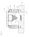
- Authority
- EP
- European Patent Office
- Prior art keywords
- sawing device
- accordance
- flying saw
- drive unit
- sawing
- Prior art date
- Legal status (The legal status is an assumption and is not a legal conclusion. Google has not performed a legal analysis and makes no representation as to the accuracy of the status listed.)
- Active
Links
Images


Classifications
-
- B—PERFORMING OPERATIONS; TRANSPORTING
- B23—MACHINE TOOLS; METAL-WORKING NOT OTHERWISE PROVIDED FOR
- B23D—PLANING; SLOTTING; SHEARING; BROACHING; SAWING; FILING; SCRAPING; LIKE OPERATIONS FOR WORKING METAL BY REMOVING MATERIAL, NOT OTHERWISE PROVIDED FOR
- B23D45/00—Sawing machines or sawing devices with circular saw blades or with friction saw discs
- B23D45/18—Machines with circular saw blades for sawing stock while the latter is travelling otherwise than in the direction of the cut
- B23D45/20—Flying sawing machines, the saw carrier of which is reciprocated in a guide and moves with the travelling stock during sawing
-
- B—PERFORMING OPERATIONS; TRANSPORTING
- B23—MACHINE TOOLS; METAL-WORKING NOT OTHERWISE PROVIDED FOR
- B23D—PLANING; SLOTTING; SHEARING; BROACHING; SAWING; FILING; SCRAPING; LIKE OPERATIONS FOR WORKING METAL BY REMOVING MATERIAL, NOT OTHERWISE PROVIDED FOR
- B23D45/00—Sawing machines or sawing devices with circular saw blades or with friction saw discs
- B23D45/12—Sawing machines or sawing devices with circular saw blades or with friction saw discs with a circular saw blade for cutting tubes
- B23D45/126—Sawing machines or sawing devices with circular saw blades or with friction saw discs with a circular saw blade for cutting tubes with the tool turning around the workpieces
-
- Y—GENERAL TAGGING OF NEW TECHNOLOGICAL DEVELOPMENTS; GENERAL TAGGING OF CROSS-SECTIONAL TECHNOLOGIES SPANNING OVER SEVERAL SECTIONS OF THE IPC; TECHNICAL SUBJECTS COVERED BY FORMER USPC CROSS-REFERENCE ART COLLECTIONS [XRACs] AND DIGESTS
- Y10—TECHNICAL SUBJECTS COVERED BY FORMER USPC
- Y10T—TECHNICAL SUBJECTS COVERED BY FORMER US CLASSIFICATION
- Y10T83/00—Cutting
- Y10T83/202—With product handling means
- Y10T83/2092—Means to move, guide, or permit free fall or flight of product
-
- Y—GENERAL TAGGING OF NEW TECHNOLOGICAL DEVELOPMENTS; GENERAL TAGGING OF CROSS-SECTIONAL TECHNOLOGIES SPANNING OVER SEVERAL SECTIONS OF THE IPC; TECHNICAL SUBJECTS COVERED BY FORMER USPC CROSS-REFERENCE ART COLLECTIONS [XRACs] AND DIGESTS
- Y10—TECHNICAL SUBJECTS COVERED BY FORMER USPC
- Y10T—TECHNICAL SUBJECTS COVERED BY FORMER US CLASSIFICATION
- Y10T83/00—Cutting
- Y10T83/465—Cutting motion of tool has component in direction of moving work
Definitions
- the invention relates to a flying saw according to the preamble of patent claim 1, with at least one guide rail on which a sawing device is mounted movably along at least one traction drive along profile or pipe material to be cut to predetermined lengths, in particular during cutting to length synchronized with the advancing movement of the profile or pipe material.
- a saw is for example from the US 2003/0209116 A1 out.
- flying saws To cut to length profiles or longitudinally welded pipe strands with a diameter of more than 100mm, which are theoretically endless, so-called flying saws are used, which are synchronized with the feed of the profile or pipe string and the separation process the advance of the profile or Continue with the tubing.
- flying saws as for example from the DE 31 12 519 A1 are known include a sawing device which is movably disposed within a machine bed. For this purpose, guide and drive elements are arranged in the machine bed. To move the sawing device along the machine bed a rack drive is regularly arranged in the machine bed.
- the invention aims to remedy this situation.
- the invention has for its object to provide a flying saw, which can be produced with minimal effort and is avoided in the contamination of the drive by coolant and chips. According to the invention, this object is solved by the features of claim 1.
- a flying saw is created, which can be produced with minimal effort and in which contamination of the drive by coolant and chips is avoided.
- By arranging the at least one guide rail and the drive above the sawing device contamination of the drive by cooling fluid and chips is counteracted. A complex creation of a machine bed is eliminated.
- two guide rails are arranged, which receive three on this movable cross member, whereby a portal is formed, on which the sawing device is attached.
- a frame element for receiving the sawing device is advantageously formed on a cross member.
- the sawing device is movable horizontally along at least one drive along the cross member and / or vertically along an orthogonal to the cross member. As a result, an optimal employment of the sawing device is made possible to be cut rod or tube material.
- the at least one drive comprises a spindle drive.
- At least one vertical guide is present within the frame element, via which the sawing device is connected to the frame element. This allows a guided vertical movement of the sawing device within the frame member.
- the sawing device is detachably connected to the frame element.
- the releasable connection is one with the vertical Movement of the sawing device formed within the frame member arranged threaded spindle.
- a simple extraction and threading of the sawing device in advantageously laterally arranged in the frame element vertical guide rails is made possible.
- the sawing device is formed by a vortex separating device.
- a vortex separation device As a result, an effective separation process for cutting profile or pipe material is possible.
- such a vortex separation device in a compact design can be realized, whereby centrifugal forces can be reduced and acceleration processes can be optimized.
- the at least one drive comprises a servomotor.
- the at least one drive is a rack drive, wherein a rack of a rack drive is arranged parallel to at least one guide rail.
- a uniform drive of the sawing device receiving cross member is made possible.
- a lateral adjustment of the sawing device due to a non-uniform drive is prevented.
- a rack of a rack and pinion drive is arranged parallel to each guide rail.
- the at least one traction drive is an electromagnetic floating drive.
- the cross member is formed on the portal in the manner of an electromagnetic levitation system, in which cause the attraction of electric or permanent magnets in a known manner the carrying and guiding the cross member on the two guide rails.
- a chip conveyor is arranged below the at least one sawing device. This allows a controlled return of coolant and chips for subsequent recycling.
- At least one clamping module for receiving a profile or pipe material to be cut is arranged, which is connected to a respective cross member and can be adjusted to the sawing device.
- the clamping modules can be moved or replaced independently of the sawing device, whereby, for example, the accessibility to the sawing tool improved and its wear-related change is facilitated.
- a clamping module is arranged on each side of the saw module.
- the pipe material to be cut off can be fixed on both sides of the sawing tool. In this case, a very close employment of the clamping modules to the sawing tool is possible, whereby vibrations during the sawing process can be reduced.
- the flying saw selected as an exemplary embodiment consists essentially of a rail system 1, on which a cross member 2 slidably disposed is that receives a removable frame 3 for receiving a vertebral separating device 4.
- a clamping module 5 is arranged for clamping of profile or tube material to be separated.
- a chip conveyor 6 is arranged for the removal of chips and coolant.
- the rail system 1 is formed from parallel stators 11, on which two mutually parallel supports 12 are attached.
- the stand 11 are screwed in the embodiment with a cast in a foundation 8 support section 81.
- a rail 13 for displaceable support of the cross member 2 is arranged on each of these.
- Parallel to the rails 13, a rack 14 is arranged on the support 12 in each case on the outside.
- the cross members 2 are formed in the embodiment by two transversely to the carriers 12 arranged carrier 21, which are connected to each other via two arranged along the carrier 12 profiles 22, so that a rectangular frame is formed. Below the profiles 22, a guide 23 for engagement with the rails 13 of the rail system 1 is arranged on each of these. At both ends of a carrier 21, a servo drive 24 is arranged in each case, the drive axle is provided with a gear 241 which engages in a rack 14 of the rail system. About the servo drives 24, the cross member 2 along the rails 13 of the rail system 1 are movable.
- the cross members 2 are identical in the embodiment for the vortex separation devices as for the clamping modules 5.
- a removable frame 3 is attached via horizontal guide rails 311.
- the removable frame 3 is formed from a support frame 31, on which opposite two side support 32 are arranged.
- the support frame 31 is connected to a horizontal linear drive 312, via which a horizontal movement of the removable frame 3 is made possible relative to the cross members 2.
- a spindle 33 is arranged on the support frame 31, which is drivable via a spindle drive 321 and connected to the vertebral separating device 4 via a coupling 332.
- the coupling 332 is formed hydraulically locked and unlocked in the embodiment. Via the spindle 33, the vertebral separating device 4 along the vertical side guides 321 along the side support 32 is slidable.
- Wirbeltrennvoriquesen for separating tubular and rod-shaped workpieces in the swirl process are for example from EP 490 328 B1 known.
- a swirling process is a machining process in which the tool orbits the workpiece in a spiral-twisted manner. The cutting depth is produced by one or more high-speed rotating knives in one operation.
- the inner circumferential surface formed by the cutting tool rolls on the cylindrical outer circumferential surface of the workpiece to be machined. This movement process is superimposed on the constantly rotating movement of the cutting tool.
- the swirling method has the advantage that a large number of cutting tools, in particular cutting steels, can be arranged next to one another, which are in engagement with the workpiece at the same time over a larger segment area.
- the vertebral separating device 4 has an integrated drive 41.
- the drive is designed as an electromagnetic rotary direct drive.
- positioning holes 332 are further arranged in the embodiment.
- the positioning holes 332 are used for the exact positioning of a - not shown - movable lifting device, which is provided with side guides which correspond in the position employed with the side guides 321 of the side support, such that the vertebral separating device 4 are moved via the spindle 33 in the side support of the lifting device and then decoupled from the spindle.
- a simple replacement of the vertebral separating device 4 is possible.
- positioning aids arranged on the lifting device are introduced into the position bores, so that a positionally accurate connection between the lifting device and the side supports is achieved.
- positioning holes and positioning pins may also be conical.
- a clamping module 5 is arranged on each two transverse beams 21 for clamping the profile or tubular material to be cut.
- the clamping module 5 is formed by a console 50 connected to the cross members 2, which accommodates three clamping jaws 51 which are offset by 120 ° and which can be pressed by a hydraulic cylinder 52 against a pipe 7 to be clamped.
- a - not shown - roller guide is arranged as a support of the rod or pipe material to be cut off .
- the roller guide (not shown) essentially comprises mutually employed tapered rollers on which the rod or tube material to be cut is slidably mounted.
- the clamping modules 5 are connected via hydraulic locks 53 releasably connected to two transverse struts 54, which are fixed to the two the removable frame 3 receiving cross members 2.
- the clamping modules 5 can be released by hydraulic unlocking of the cross braces 54 and moved separately along the rails 13 of the rail system 1.
- the clamping modules 5 are formed identically and arranged mirror-symmetrically on both sides of the vertebral separating device.
Landscapes
- Engineering & Computer Science (AREA)
- Mechanical Engineering (AREA)
- Sawing (AREA)
Description
- Die Erfindung betrifft eine fliegende Säge gemäß dem Oberbegriff des Patentanspruchs 1, mit wenigstens einer Führungsschiene, auf dem eine Sägevorrichtung über wenigstens einen Fahrantrieb entlang auf vorgegebene Längen abzulängenden Profil- oder Rohrmaterial verfahrbar gelagert ist, insbesondere während des Ablängens synchron zur Vorschubbewegung des Profil- oder Rohrmaterials. Eine derartige Säge geht beispielsweise aus der
US 2003/0209116 A1 hervor. - Zum Ablängen von Profilen oder von längsnahtgeschweißten Rohrsträngen mit einem Durchmesser von mehr als 100mm, die theoretisch endlos sind, kommen so genannte fliegende Sägen zum Einsatz, welche mit dem Vorschub des Profil- bzw. Rohrstrangs synchronisiert sind und den Trennvorgang dem Vorschub des Profil- bzw. Rohrstranges folgend vornehmen. Derartige fliegende Sägen, wie sie beispielsweise aus der
DE 31 12 519 A1 bekannt sind, umfassen eine Sägevorrichtung, die innerhalb eines Maschinenbetts bewegbar angeordnet ist. Hierzu sind in dem Maschinenbett Führungs- und Antriebselemente angeordnet. Zur Bewegung der Sägevorrichtung entlang des Maschinenbetts ist dabei regelmäßig in dem Maschinenbett ein Zahnstangenantrieb angeordnet. - Nachteilig an den vorbekannten fliegenden Sägen ist, dass die Erstellung des Maschinenbetts sich als sehr aufwendig gestaltet. Darüber hinaus ist der Zahnstangenantrieb Verschmutzungen durch mit Kühlflüssigkeit angespülte Späne ausgesetzt.
- Hier will die Erfindung Abhilfe schaffen. Der Erfindung liegt die Aufgabe zur Grunde, eine fliegende Säge zu schaffen, welche aufwandminimiert herstellbar ist und bei der Verschmutzungen des Antriebs durch Kühlflüssigkeit und Späne vermieden ist. Gemäß der Erfindung wird diese Aufgabe durch die Merkmale des Patentanspruchs 1 gelöst.
- Mit der Erfindung ist eine fliegende Säge geschaffen, welche aufwandminimiert herstellbar ist und bei der eine Verschmutzung des Antriebs durch Kühlflüssigkeit und Späne vermieden ist. Durch die Anordnung der wenigstens einen Führungsschiene sowie dem Fahrantrieb oberhalb der Sägevorrichtung ist einer Verunreinigung des Antriebs durch Kühlflüssigkeit und Späne entgegengewirkt. Eine aufwendige Erstellung eines Maschinenbetts entfällt.
- Erfindungsgemäß sind zwei Führungsschienen angeordnet, die drei auf diesen verfahrbare Querträger aufnehmen, wodurch ein Portal gebildet ist, an dem die Sägevorrichtung befestigt ist. Hierdurch ist eine zuverlässige Aufhängung der Sägevorrichtung erzielt. Dabei ist vorteilhaft an einem Querträger ein Rahmenelement zur Aufnahme der Sägevorrichtung gebildet.
- Die Sägevorrichtung ist über wenigstens einen Antrieb horizontal entlang des Querträgers und/oder vertikal entlang einer orthogonal zu dem Querträger bewegbar. Hierdurch ist eine optimale Anstellung der Sägevorrichtung zu dem abzulängenden Stangen- oder Rohrmaterial ermöglicht.
- In weiterer Ausgestaltung der Erfindung umfasst der wenigstens eine Antrieb einen Spindeltrieb. Hierdurch ist eine Feineinstellung der Sägevorrichtung ermöglicht.
- In Weiterbildung der Erfindung ist innerhalb des Rahmenelements wenigstens eine vertikale Führung vorhanden, über welche die Sägevorrichtung mit dem Rahmenelement verbunden ist. Hierdurch ist eine geführte vertikale Bewegung der Sägevorrichtung innerhalb des Rahmenelements ermöglicht.
- In weiterer Ausgestaltung der Erfindung ist die Sägevorrichtung lösbar mit dem Rahmenelement verbunden. Hierdurch ist ein einfacher Austausch der Sägevorrichtung ermöglicht. Bevorzugt ist die lösbare Verbindung mit einer zur vertikalen Bewegung der Sägevorrichtung innerhalb des Rahmenelements angeordneten Gewindespindel gebildet. Hierdurch ist ein einfaches Aus- und Einfädeln der Sägevorrichtung in vorteilhaft seitlich in dem Rahmenelement angeordneten vertikalen Führungsschienen ermöglicht.
- Gemäß der Erfindung ist die Sägevorrichtung durch eine Wirbeltrennvorrichtung gebildet. Hierdurch ist ein effektiver Trennvorgang zum Ablängen von Profil- oder Rohrmaterial ermöglicht. Zudem ist eine derartige Wirbeltrennvorrichtung in kompakter Bauweise realisierbar, wodurch Fliehkräfte reduziert und Beschleunigungsvorgänge optimiert werden können.
- In weiterer Ausgestaltung der Erfindung umfasst der wenigstens eine Antrieb einen Servomotor. Hierdurch ist eine genaue Anstellung der Sägevorrichtung an das abzulängende Stangen- oder Rohrmaterial ermöglicht.
- In weiterer Ausgestaltung der Erfindung ist der wenigstens eine Fahrantrieb ein Zahnstangenantrieb, wobei parallel zu wenigstens einer Führungsschiene eine Zahnstange eines Zahnstangenantriebs angeordnet ist. Hierdurch ist ein gleichmäßiger Antrieb des die Sägevorrichtung aufnehmenden Querträgers ermöglicht. Ein seitliches Verstellen der Sägevorrichtung auf Grund eines ungleichmäßigen Antriebs ist so verhindert. Vorteilhaft ist parallel zu jeder Führungsschiene eine Zahnstange eines Zahnstangenantriebs angeordnet.
- In vorteilhafter Ausgestaltung der Erfindung ist der wenigstens eine Fahrantrieb ein elektromagnetischer Schwebeantrieb. Hierbei ist der Querträger auf dem Portal in Art eines elektromagnetischen Schwebesystems ausgebildet, bei dem die Anziehungskräfte von Elektro- oder Permanentmagneten in bekannter Art und Weise das Tragen und Führen des Querträgers auf den beiden Führungsschienen bewirken. Hierdurch sind Reibungskräfte minimiert, wodurch hohe Beschleunigungen der Sägevorrichtung entlang des abzulängenden Stangen- oder Rohrmaterials realisierbar sind.
- Vorteilhaft ist unterhalb der wenigstens einen Sägevorrichtung eine Spänefördereinrichtung angeordnet. Hierdurch ist eine geregelte Rückführung von Kühlflüssigkeit und Spänen für ein nachfolgendes Recycling ermöglicht.
- Gemäß der Erfindung ist wenigstens ein Spannmodul zur Aufnahme eines abzulängenden Profil- oder Rohrmaterials angeordnet, das mit jeweils einem Querträger verbunden und an die Sägevorrichtung anstellbar ist. Hierdurch ist ein modularer Aufbau erzielt, bei dem die Spannmodule unabhängig von der Sägevorrichtung bewegt oder ausgetauscht werden können, wodurch beispielsweise die Zugänglichkeit zum Sägewerkzeug verbessert und dessen verschleißbedingter Wechsel erleichtert ist. In Strangrichtung ist beidseitig des Sägemoduls jeweils ein solches Spannmodul angeordnet. In den Spannmodulen kann das abzulängende Rohrmaterial so beidseitig des Sägewerkzeugs fixiert werden. Dabei ist eine sehr nahe Anstellung der Spannmodule an das Sägewerkzeug möglich, wodurch Vibrationen während des Sägevorgangs reduziert werden können.
- Andere Weiterbildungen und Ausgestaltungen der Erfindung sind in den übrigen Unteransprüchen angegeben. Ein Ausführungsbeispiel der Erfindung ist in den Zeichnungen dargestellt und wird nachfolgend im Einzelnen beschrieben. Es zeigen:
- Figur 1
- die schematische Darstellung einer fliegenden Säge mit zwei Sägevorrichtungen in der Draufsicht;
- Figur 2
- die schematische Darstellung einer Sägevorrichtung der fliegenden Säge aus
Figur 1 ; - Figur 3
- die schematische Darstellung der Sägevorrichtung aus
Figur 2 in der Seitenansicht und - Figur 4
- die schematische Darstellung eines Einspannmoduls der Sägevorrichtung aus
Figur 1 . - Die als Ausführungsbeispiel gewählte fliegende Säge besteht im Wesentlichen aus einem Schienensystem 1, auf dem ein Querträger 2 verschiebbar angeordnet ist, der einen Wechselrahmen 3 zur Aufnahme einer Wirbeltrennvorrichtung 4 aufnimmt. Beidseitig der Wirbeltrennvorrichtung 4 ist ein Spannmodul 5 zur Einspannung von zu trennendem Profil- oder Rohrmaterial angeordnet. Unterhalb der Wirbeltrennvorrichtung 4 ist ein Spanförderer 6 zum Abtransport von Spänen und Kühlflüssigkeit angeordnet.
- Das Schienensystem 1 ist gebildet aus parallel angeordneten Ständern 11, auf denen zwei zueinander parallel angeordnete Träger 12 befestigt sind. Die Ständer 11 sind im Ausführungsbeispiel mit einem in einem Fundament 8 eingegossenen Tragprofil 81 verschraubt. Entlang der Träger 12 ist auf diesen jeweils eine Schiene 13 zur verschieblichen Auflage der Querträger 2 angeordnet. Parallel zu den Schienen 13 ist jeweils außen eine Zahnstange 14 auf dem Träger 12 angeordnet.
- Die Querträger 2 sind im Ausführungsbeispiel gebildet durch zwei quer zu den Trägern 12 angeordnete Träger 21, welche über zwei entlang der Träger 12 angeordnete Profile 22 miteinander verbunden sind, sodass ein rechteckförmiger Rahmen gebildet ist. Unterhalb der Profile 22 ist an diesen jeweils eine Führung 23 zum Eingriff mit den Schienen 13 des Schienensystems 1 angeordnet. An beiden Enden eines Trägers 21 ist jeweils ein Servoantrieb 24 angeordnet, dessen Antriebsachse mit einem Zahnrad 241 versehen ist, das in eine Zahnstange 14 des Schienensystems eingreift. Über die Servoantriebe 24 sind die Querträger 2 entlang der Schienen 13 des Schienensystems 1 bewegbar. Die Querträger 2 sind im Ausführungsbeispiel für die Wirbeltrennvorrichtungen wie für die Spannmodule 5 identisch ausgebildet.
- An zwei Querträgern 21 ist über horizontale Führungsschienen 311 ein Wechselrahmen 3 befestigt. Der Wechselrahmen 3 ist gebildet aus einem Traggerüst 31, an dem gegenüberliegend zwei Seitenträger 32 angeordnet sind. Dabei ist das Traggerüst 31 mit einem horizontalen Lineartrieb 312 verbunden, über den eine horizontale Bewegung des Wechselrahmens 3 relativ zu den Querträgern 2 ermöglicht ist. An den Seitenträgern 32 sind an ihren dem jeweils gegenüberliegend angeordneten Seitenträger 32 zugewandten Seiten jeweils vertikale Seitenführungen 321 zur verschiebbaren Aufnahme der Wirbeltrennvorrichtung 4 angeordnet. Weiterhin ist an dem Traggerüst 31 eine Spindel 33 angeordnet, die über einen Spindelantrieb 321 antreibbar und mit der Wirbeltrennvorrichtung 4 über eine Kupplung 332 verbunden ist. Die Kupplung 332 ist im Ausführungsbeispiel hydraulisch ver- und entriegelbar ausgebildet. Über die Spindel 33 ist die Wirbeltrennvorrichtung 4 entlang der vertikalen Seitenführungen 321 entlang der Seitenträger 32 verschiebbar.
- Wirbeltrennvorrichtungen zum Trennen von rohr- und stangenförmigen Werkstücken im Wirbelverfahren sind beispielsweise aus der
EP 490 328 B1 - An den freien Enden der Seitenträger 32 sind im Ausführungsbeispiel weiterhin Positionierbohrungen 332 angeordnet. Die Positionierbohrungen 332 dienen der exakten Positionierung einer - nicht dargestellten - verfahrbaren Hubvorrichtung, die mit Seitenführungen versehen ist, welche im angestellter Position mit den Seitenführungen 321 der Seitenträger korrespondieren, derart, dass die Wirbeltrennvorrichtung 4 über die Spindel 33 in die Seitenträger der Hubvorrichtung bewegt werden und anschließend von der Spindel entkoppelt werden kann. Über eine solche Hubvorrichtung ist ein einfacher Austausch der Wirbeltrennvorrichtung 4 ermöglicht. Zur Positionierung werden an der Hubvorrichtung angeordnete Positionshilfen in die Positionsbohrungen eingeführt, so dass eine positionsgenaue Verbindung zwischen Hubvorrichtung und den Seitenträgern erzielt ist. Zur Vereinfachung des Einfädelvorgangs können Positionierbohrungen und Positionierstifte auch konisch ausgebildet sein.
- Beidseitig des von der Wirbeltrennvorrichtung 4 aufgenommen Wirbelwerkzeugs 42 ist an jeweils zwei Querträgern 21 jeweils ein Spannmodul 5 zur Einspannung des abzulängenden Profil- oder Rohrmaterials angeordnet. Das Spannmodul 5 ist gebildet durch eine mit den Querträgern 2 verbundene Konsole 50, welche drei um jeweils 120° versetzt angeordnete Spannbacken 51 aufnimmt, die über Hydraulikzylinder 52 gegen ein einzuspannendes Rohr 7 pressbar sind. Weiterhin ist als Auflager des abzulängenden Stangen- oder Rohrmaterials eine - nicht dargestellte - Rollenführung angeordnet. Die - nicht dargestellte - Rollenführung umfasst im Wesentlichen zueinander angestellte Kegelrollen, auf denen das abzulängende Stangen- oder Rohrmaterial verschieblich gelagert ist. Die Spannmodule 5 sind über hydraulische Verriegelungen 53 lösbar mit zwei Querstreben 54 verbunden, die an den beiden den Wechselrahmen 3 aufnehmenden Querträgern 2 befestigt sind. Die Spannmodule 5 können durch hydraulische Entriegelung von den Querstreben 54 gelöst und separat entlang den Schienen 13 des Schienensystems 1 verfahren werden. Im Ausführungsbeispiel sind die Spannmodule 5 identisch ausgebildet und spiegelgleich zueinander beidseitig der Wirbeltrennvorrichtung angeordnet.
Claims (11)
- Fliegende Säge, mit wenigstens einer Führungsschiene (13), auf dem eine Sägevorrichtung über wenigstens einen Fahrantrieb (24) entlang auf vorgegebene Längen abzulängendem Profil- oder Rohrmaterial verfahrbar gelagert ist, insbesondere während des Ablängens synchron zur Vorschubbewegung des Profil- oder Rohrmaterials, wobei die wenigstens eine Führungsschiene (13) wie auch der Fahrantrieb (24) oberhalb der Sägevorrichtung (4) angeordnet ist, wobei insbesondere kein Maschinenbett vorhanden ist, dadurch gekennzeichnet, dass die Sägevorrichtung (4) durch eine Wirbeltrennvorrichtung (4) mit einem Wirbelsägewerkzeug mit innenliegender Verzahnung gebildet ist, wobei zwei Führungsschienen (13) angeordnet sind, die drei auf diesen verfahrbare Querträger (2) aufnehmen, wodurch ein Portal gebildet ist, an dem die Sägevorrichtung (4) befestigt ist, wobei beidseitig der Sägevorrichtung (4) jeweils ein Spannmodul (5) zur Aufnahme eines abzulängenden Profil- oder Rohrmaterials angeordnet ist, das mit jeweils einem Querträger (2) verbunden und an die Sägevorrichtung (4) anstellbar ist.
- Fliegende Säge nach einem der vorgenannten Ansprüche, dadurch gekennzeichnet, dass an einem Querträger (2) ein Rahmenelement (3) zur Aufnahme der Sägevorrichtung (4) gebildet ist.
- Fliegende Säge nach Anspruch 2, dadurch gekennzeichnet, dass die Sägevorrichtung (4) über wenigstens einen Antrieb (34, 351) horizontal entlang des Querträgers (2) und/oder vertikal entlang einer Orthogonalen zu dem Querträger (2) bewegbar ist.
- Fliegende Säge nach Anspruch 3, dadurch gekennzeichnet, dass der wenigstens eine Antrieb (34, 351) einen Spindelantrieb umfasst.
- Fliegende Säge nach einem der Ansprüche 3 und 4, dadurch gekennzeichnet, dass innerhalb des Rahmenelements (3) wenigstens eine vertikale Führung (321) vorhanden ist, über welche die Sägevorrichtung (4) mit dem Rahmenelement (3) verbunden ist.
- Fliegende Säge nach einem der Ansprüche 2 bis 5, dadurch gekennzeichnet, dass die Sägevorrichtung (4) lösbar mit dem Rahmenelement verbunden ist.
- Fliegende Säge nach einem der vorgenannten Ansprüche, dadurch gekennzeichnet, dass der wenigstens eine Fahrantrieb (24) einen Servomotor umfasst.
- Fliegende Säge nach einem der vorgenannten Ansprüche, dadurch gekennzeichnet, dass der wenigstens eine Fahrantrieb (24) ein Zahnstangenantrieb ist, wobei parallel zu wenigstens einer Führungsschiene (13) eine Zahnstange (14) eines Zahnstangenantriebs angeordnet ist.
- Fliegende Säge nach Anspruch 8, dadurch gekennzeichnet, dass parallel zu jeder Führungsschiene (13) eine Zahnstange (14) eines Zahnstangenantriebs angeordnet ist.
- Fliegende Säge nach einem der Ansprüche 2 bis 8, dadurch gekennzeichnet, dass der wenigstens eine Fahrantrieb (24) ein elektromagnetischer Schwebeantrieb ist.
- Fliegende Säge nach einem der vorgenannten Ansprüche, dadurch gekennzeichnet, dass unterhalb der wenigstens einen Sägevorrichtung (4) eine Spanfördereinrichtung (5) angeordnet ist.
Priority Applications (2)
| Application Number | Priority Date | Filing Date | Title |
|---|---|---|---|
| EP20110003942 EP2522448B1 (de) | 2011-05-12 | 2011-05-12 | Fliegende Säge |
| US13/424,809 US20120285307A1 (en) | 2011-05-12 | 2012-03-20 | Flying saw |
Applications Claiming Priority (1)
| Application Number | Priority Date | Filing Date | Title |
|---|---|---|---|
| EP20110003942 EP2522448B1 (de) | 2011-05-12 | 2011-05-12 | Fliegende Säge |
Publications (2)
| Publication Number | Publication Date |
|---|---|
| EP2522448A1 EP2522448A1 (de) | 2012-11-14 |
| EP2522448B1 true EP2522448B1 (de) | 2013-08-28 |
Family
ID=44675383
Family Applications (1)
| Application Number | Title | Priority Date | Filing Date |
|---|---|---|---|
| EP20110003942 Active EP2522448B1 (de) | 2011-05-12 | 2011-05-12 | Fliegende Säge |
Country Status (2)
| Country | Link |
|---|---|
| US (1) | US20120285307A1 (de) |
| EP (1) | EP2522448B1 (de) |
Families Citing this family (2)
| Publication number | Priority date | Publication date | Assignee | Title |
|---|---|---|---|---|
| CN109352084B (zh) * | 2018-08-16 | 2020-10-09 | 安徽嘉诚建设工程有限公司 | 一种建筑工地施工用建筑板材分段装置 |
| CN109262677A (zh) * | 2018-09-13 | 2019-01-25 | 江阴市永昌交通机械部件有限公司 | 一种汽车软管加工用剪切装置 |
Family Cites Families (21)
| Publication number | Priority date | Publication date | Assignee | Title |
|---|---|---|---|---|
| US1699582A (en) * | 1927-06-20 | 1929-01-22 | Henry C Breidenbach | Veneer log-scoring mechanism |
| US2007225A (en) * | 1932-05-09 | 1935-07-09 | Karl Strobel Corp | Electric arc cutting machine |
| US2159282A (en) * | 1938-02-28 | 1939-05-23 | Marino Louis | Bat-forming table |
| US2506076A (en) * | 1948-09-16 | 1950-05-02 | Swenson Granite Co Inc John | Stonecutting machine |
| US2605841A (en) * | 1949-06-06 | 1952-08-05 | Earl R Overman | Drive for flying knives |
| US3072004A (en) * | 1959-07-31 | 1963-01-08 | Armstrong Rubber Co | Severing apparatus |
| DE2800528A1 (de) * | 1978-01-07 | 1979-07-12 | Iwm Ing Buero | Einrichtung zum trennschleifen von heissem walzgut |
| DE2948103A1 (de) * | 1979-11-29 | 1981-06-04 | Fried. Krupp Gmbh, 4300 Essen | Vorrichtung zum zerteilen in richtung seiner laengserstreckung bewegten stangenfoermigen materials |
| DE3112519A1 (de) | 1981-03-30 | 1982-11-04 | Hartmann & Lämmle GmbH & Co KG, 7255 Rutesheim | Fliegende saege mit einem eine saege tragenden saegeschlitten |
| US4444077A (en) * | 1981-09-25 | 1984-04-24 | Georgia-Pacific Corporation | Flying saw apparatus |
| JPS61111806A (ja) * | 1984-11-07 | 1986-05-29 | Yazaki Kako Kk | 走行するパイプ等の定寸自動切断装置 |
| IT1211447B (it) * | 1987-11-02 | 1989-10-26 | Raffaele Lapiccirella | Dispositivo per il taglio di lastre di cemento amianto o simili materiali |
| US4864906A (en) * | 1988-01-29 | 1989-09-12 | Hall Troy L | Core slabbing machine |
| DE3917002C1 (de) * | 1989-05-24 | 1990-05-10 | Elhaus Industrieanlagen Gmbh, 7703 Rielasingen-Worblingen, De | |
| JPH03221311A (ja) * | 1990-01-23 | 1991-09-30 | Mitsubishi Heavy Ind Ltd | ミーリング式走行鋼管切断機 |
| US5238337A (en) | 1990-12-14 | 1993-08-24 | Maschinenfabrik Ravensburg Ag | Method of machining round material or the like by the whirling process |
| US5138920A (en) * | 1991-08-09 | 1992-08-18 | Ryobi America Corporation | Passive differential power shunted load and speed control apparatus |
| US6923101B2 (en) * | 2002-05-10 | 2005-08-02 | Mid-South Engineering Co., Inc | Continuous log bucking saw system and method |
| US20060000521A1 (en) * | 2004-06-30 | 2006-01-05 | Edward Komori | Board fencing system |
| US20060037450A1 (en) * | 2004-08-17 | 2006-02-23 | Pobuda Ronald H | Flying saw and flighted chain conveyor apparatus |
| IT1392045B1 (it) * | 2008-09-12 | 2012-02-09 | Olimpia 80 Srl | Macchina verticale a doppia lama oscillante per il taglio di tubi e metodo di taglio mediante detta macchina |
-
2011
- 2011-05-12 EP EP20110003942 patent/EP2522448B1/de active Active
-
2012
- 2012-03-20 US US13/424,809 patent/US20120285307A1/en not_active Abandoned
Also Published As
| Publication number | Publication date |
|---|---|
| EP2522448A1 (de) | 2012-11-14 |
| US20120285307A1 (en) | 2012-11-15 |
Similar Documents
| Publication | Publication Date | Title |
|---|---|---|
| DE3035451C2 (de) | ||
| EP0968069B2 (de) | Werkzeugmaschine | |
| DE4113629C2 (de) | Reihenbohr- und Fräsmaschine | |
| EP2647457B1 (de) | Maschine zum Abtrennen von Abschnitten von stangen- oder rohrförmigen Werkstücken | |
| EP2036643A2 (de) | Werkzeugmaschine zum Schneiden und zum Bohren von Metallprofilen | |
| EP0895825B1 (de) | Zentriermaschine | |
| DE4101749A1 (de) | Fahrbare stahlrohr-fraesschneidemaschine | |
| DE2535202A1 (de) | Werkzeugmaschine und verfahren zur bearbeitung von werkstuecken | |
| DE69805961T2 (de) | Bearbeitungsvorrichtung zur spanenden metallbearbeitung, mit massivem block und gleitender säule, sowie maschine mit diesem massiven block und gleitender säule, sowie maschine mit dieser vorrichtung | |
| DE4015570A1 (de) | Werkzeugmaschine, insbesondere vertikal-schleifmaschine und verfahren zum bearbeiten von werkstuecken mit dieser maschine | |
| EP2193895A1 (de) | Plattenaufteilanlage sowie Verfahren zu deren Betrieb | |
| EP2522449B1 (de) | Fliegende Säge | |
| DE2901005A1 (de) | Bohranlage fuer profilstaehle | |
| DE102006027013B3 (de) | Maschine und Verfahren zum Formatieren von Platten | |
| EP2522448A1 (de) | Fliegende Säge | |
| DE202011100634U1 (de) | Fliegende Säge | |
| EP2185331B1 (de) | Vorrichtung zur bearbeitung von werkstücken aus holz, kunststoff und dergleichen sowie verfahren zum bearbeiten von solchen werkstücken | |
| DE19911156C2 (de) | Drehmaschine zur Bearbeitung von wellenförmigen Werkstücken | |
| DE60014192T2 (de) | Vorrichtung und verfahren zur herstellung von anschlussstutzen in einer abgasanlage | |
| EP0683001B1 (de) | Verfahren und Vorrichtung zum spanenden Bearbeiten von Stangen, Rohren oder Rohrluppen | |
| EP3795294A1 (de) | Schwenkvorrichtung für werkstückspindel einer werkzeugmaschine, werkzeugträger für eine werkzeugmaschine und werkzeugmaschine | |
| DE202011100631U1 (de) | Fliegende Säge | |
| DE102011118170B4 (de) | Flachbettdrehmaschine | |
| DE19710447A1 (de) | Vorrichtung zur Werkstückzuführung in einen Einspannbereich einer Werkzeugmaschine | |
| EP2206569B1 (de) | Verfahren zur Herstellung mehrerer bearbeiteter Werkstücke aus einem Rohteil |
Legal Events
| Date | Code | Title | Description |
|---|---|---|---|
| PUAI | Public reference made under article 153(3) epc to a published international application that has entered the european phase |
Free format text: ORIGINAL CODE: 0009012 |
|
| AK | Designated contracting states |
Kind code of ref document: A1 Designated state(s): AL AT BE BG CH CY CZ DE DK EE ES FI FR GB GR HR HU IE IS IT LI LT LU LV MC MK MT NL NO PL PT RO RS SE SI SK SM TR |
|
| AX | Request for extension of the european patent |
Extension state: BA ME |
|
| 17P | Request for examination filed |
Effective date: 20130111 |
|
| 17Q | First examination report despatched |
Effective date: 20130225 |
|
| GRAP | Despatch of communication of intention to grant a patent |
Free format text: ORIGINAL CODE: EPIDOSNIGR1 |
|
| INTG | Intention to grant announced |
Effective date: 20130426 |
|
| GRAS | Grant fee paid |
Free format text: ORIGINAL CODE: EPIDOSNIGR3 |
|
| GRAA | (expected) grant |
Free format text: ORIGINAL CODE: 0009210 |
|
| AK | Designated contracting states |
Kind code of ref document: B1 Designated state(s): AL AT BE BG CH CY CZ DE DK EE ES FI FR GB GR HR HU IE IS IT LI LT LU LV MC MK MT NL NO PL PT RO RS SE SI SK SM TR |
|
| REG | Reference to a national code |
Ref country code: GB Ref legal event code: FG4D Free format text: NOT ENGLISH |
|
| REG | Reference to a national code |
Ref country code: CH Ref legal event code: EP |
|
| REG | Reference to a national code |
Ref country code: AT Ref legal event code: REF Ref document number: 629006 Country of ref document: AT Kind code of ref document: T Effective date: 20130915 |
|
| REG | Reference to a national code |
Ref country code: IE Ref legal event code: FG4D Free format text: LANGUAGE OF EP DOCUMENT: GERMAN |
|
| REG | Reference to a national code |
Ref country code: DE Ref legal event code: R096 Ref document number: 502011001228 Country of ref document: DE Effective date: 20131024 |
|
| REG | Reference to a national code |
Ref country code: LT Ref legal event code: MG4D |
|
| REG | Reference to a national code |
Ref country code: NL Ref legal event code: VDEP Effective date: 20130828 |
|
| PG25 | Lapsed in a contracting state [announced via postgrant information from national office to epo] |
Ref country code: HR Free format text: LAPSE BECAUSE OF FAILURE TO SUBMIT A TRANSLATION OF THE DESCRIPTION OR TO PAY THE FEE WITHIN THE PRESCRIBED TIME-LIMIT Effective date: 20130828 Ref country code: PT Free format text: LAPSE BECAUSE OF FAILURE TO SUBMIT A TRANSLATION OF THE DESCRIPTION OR TO PAY THE FEE WITHIN THE PRESCRIBED TIME-LIMIT Effective date: 20131230 Ref country code: IS Free format text: LAPSE BECAUSE OF FAILURE TO SUBMIT A TRANSLATION OF THE DESCRIPTION OR TO PAY THE FEE WITHIN THE PRESCRIBED TIME-LIMIT Effective date: 20131228 Ref country code: SE Free format text: LAPSE BECAUSE OF FAILURE TO SUBMIT A TRANSLATION OF THE DESCRIPTION OR TO PAY THE FEE WITHIN THE PRESCRIBED TIME-LIMIT Effective date: 20130828 Ref country code: LT Free format text: LAPSE BECAUSE OF FAILURE TO SUBMIT A TRANSLATION OF THE DESCRIPTION OR TO PAY THE FEE WITHIN THE PRESCRIBED TIME-LIMIT Effective date: 20130828 Ref country code: CY Free format text: LAPSE BECAUSE OF FAILURE TO SUBMIT A TRANSLATION OF THE DESCRIPTION OR TO PAY THE FEE WITHIN THE PRESCRIBED TIME-LIMIT Effective date: 20130918 Ref country code: NO Free format text: LAPSE BECAUSE OF FAILURE TO SUBMIT A TRANSLATION OF THE DESCRIPTION OR TO PAY THE FEE WITHIN THE PRESCRIBED TIME-LIMIT Effective date: 20131128 |
|
| REG | Reference to a national code |
Ref country code: NL Ref legal event code: VDEP Effective date: 20130828 |
|
| PG25 | Lapsed in a contracting state [announced via postgrant information from national office to epo] |
Ref country code: GR Free format text: LAPSE BECAUSE OF FAILURE TO SUBMIT A TRANSLATION OF THE DESCRIPTION OR TO PAY THE FEE WITHIN THE PRESCRIBED TIME-LIMIT Effective date: 20131129 Ref country code: LV Free format text: LAPSE BECAUSE OF FAILURE TO SUBMIT A TRANSLATION OF THE DESCRIPTION OR TO PAY THE FEE WITHIN THE PRESCRIBED TIME-LIMIT Effective date: 20130828 Ref country code: PL Free format text: LAPSE BECAUSE OF FAILURE TO SUBMIT A TRANSLATION OF THE DESCRIPTION OR TO PAY THE FEE WITHIN THE PRESCRIBED TIME-LIMIT Effective date: 20130828 Ref country code: FI Free format text: LAPSE BECAUSE OF FAILURE TO SUBMIT A TRANSLATION OF THE DESCRIPTION OR TO PAY THE FEE WITHIN THE PRESCRIBED TIME-LIMIT Effective date: 20130828 |
|
| PG25 | Lapsed in a contracting state [announced via postgrant information from national office to epo] |
Ref country code: CY Free format text: LAPSE BECAUSE OF FAILURE TO SUBMIT A TRANSLATION OF THE DESCRIPTION OR TO PAY THE FEE WITHIN THE PRESCRIBED TIME-LIMIT Effective date: 20130828 |
|
| PG25 | Lapsed in a contracting state [announced via postgrant information from national office to epo] |
Ref country code: CZ Free format text: LAPSE BECAUSE OF FAILURE TO SUBMIT A TRANSLATION OF THE DESCRIPTION OR TO PAY THE FEE WITHIN THE PRESCRIBED TIME-LIMIT Effective date: 20130828 Ref country code: NL Free format text: LAPSE BECAUSE OF FAILURE TO SUBMIT A TRANSLATION OF THE DESCRIPTION OR TO PAY THE FEE WITHIN THE PRESCRIBED TIME-LIMIT Effective date: 20130828 Ref country code: DK Free format text: LAPSE BECAUSE OF FAILURE TO SUBMIT A TRANSLATION OF THE DESCRIPTION OR TO PAY THE FEE WITHIN THE PRESCRIBED TIME-LIMIT Effective date: 20130828 Ref country code: SK Free format text: LAPSE BECAUSE OF FAILURE TO SUBMIT A TRANSLATION OF THE DESCRIPTION OR TO PAY THE FEE WITHIN THE PRESCRIBED TIME-LIMIT Effective date: 20130828 Ref country code: RO Free format text: LAPSE BECAUSE OF FAILURE TO SUBMIT A TRANSLATION OF THE DESCRIPTION OR TO PAY THE FEE WITHIN THE PRESCRIBED TIME-LIMIT Effective date: 20130828 Ref country code: EE Free format text: LAPSE BECAUSE OF FAILURE TO SUBMIT A TRANSLATION OF THE DESCRIPTION OR TO PAY THE FEE WITHIN THE PRESCRIBED TIME-LIMIT Effective date: 20130828 |
|
| PG25 | Lapsed in a contracting state [announced via postgrant information from national office to epo] |
Ref country code: ES Free format text: LAPSE BECAUSE OF FAILURE TO SUBMIT A TRANSLATION OF THE DESCRIPTION OR TO PAY THE FEE WITHIN THE PRESCRIBED TIME-LIMIT Effective date: 20130828 Ref country code: IT Free format text: LAPSE BECAUSE OF FAILURE TO SUBMIT A TRANSLATION OF THE DESCRIPTION OR TO PAY THE FEE WITHIN THE PRESCRIBED TIME-LIMIT Effective date: 20130828 |
|
| REG | Reference to a national code |
Ref country code: DE Ref legal event code: R097 Ref document number: 502011001228 Country of ref document: DE |
|
| PLBE | No opposition filed within time limit |
Free format text: ORIGINAL CODE: 0009261 |
|
| STAA | Information on the status of an ep patent application or granted ep patent |
Free format text: STATUS: NO OPPOSITION FILED WITHIN TIME LIMIT |
|
| 26N | No opposition filed |
Effective date: 20140530 |
|
| REG | Reference to a national code |
Ref country code: DE Ref legal event code: R097 Ref document number: 502011001228 Country of ref document: DE Effective date: 20140530 |
|
| PG25 | Lapsed in a contracting state [announced via postgrant information from national office to epo] |
Ref country code: LU Free format text: LAPSE BECAUSE OF FAILURE TO SUBMIT A TRANSLATION OF THE DESCRIPTION OR TO PAY THE FEE WITHIN THE PRESCRIBED TIME-LIMIT Effective date: 20140512 |
|
| REG | Reference to a national code |
Ref country code: CH Ref legal event code: PL |
|
| PG25 | Lapsed in a contracting state [announced via postgrant information from national office to epo] |
Ref country code: LI Free format text: LAPSE BECAUSE OF NON-PAYMENT OF DUE FEES Effective date: 20140531 Ref country code: MC Free format text: LAPSE BECAUSE OF FAILURE TO SUBMIT A TRANSLATION OF THE DESCRIPTION OR TO PAY THE FEE WITHIN THE PRESCRIBED TIME-LIMIT Effective date: 20130828 Ref country code: CH Free format text: LAPSE BECAUSE OF NON-PAYMENT OF DUE FEES Effective date: 20140531 |
|
| REG | Reference to a national code |
Ref country code: IE Ref legal event code: MM4A |
|
| REG | Reference to a national code |
Ref country code: FR Ref legal event code: ST Effective date: 20150130 |
|
| PG25 | Lapsed in a contracting state [announced via postgrant information from national office to epo] |
Ref country code: IE Free format text: LAPSE BECAUSE OF NON-PAYMENT OF DUE FEES Effective date: 20140512 |
|
| PG25 | Lapsed in a contracting state [announced via postgrant information from national office to epo] |
Ref country code: FR Free format text: LAPSE BECAUSE OF NON-PAYMENT OF DUE FEES Effective date: 20140602 |
|
| GBPC | Gb: european patent ceased through non-payment of renewal fee |
Effective date: 20150512 |
|
| PG25 | Lapsed in a contracting state [announced via postgrant information from national office to epo] |
Ref country code: MT Free format text: LAPSE BECAUSE OF FAILURE TO SUBMIT A TRANSLATION OF THE DESCRIPTION OR TO PAY THE FEE WITHIN THE PRESCRIBED TIME-LIMIT Effective date: 20130828 |
|
| PG25 | Lapsed in a contracting state [announced via postgrant information from national office to epo] |
Ref country code: SM Free format text: LAPSE BECAUSE OF FAILURE TO SUBMIT A TRANSLATION OF THE DESCRIPTION OR TO PAY THE FEE WITHIN THE PRESCRIBED TIME-LIMIT Effective date: 20130828 Ref country code: GB Free format text: LAPSE BECAUSE OF NON-PAYMENT OF DUE FEES Effective date: 20150512 |
|
| PG25 | Lapsed in a contracting state [announced via postgrant information from national office to epo] |
Ref country code: BG Free format text: LAPSE BECAUSE OF FAILURE TO SUBMIT A TRANSLATION OF THE DESCRIPTION OR TO PAY THE FEE WITHIN THE PRESCRIBED TIME-LIMIT Effective date: 20130828 Ref country code: RS Free format text: LAPSE BECAUSE OF FAILURE TO SUBMIT A TRANSLATION OF THE DESCRIPTION OR TO PAY THE FEE WITHIN THE PRESCRIBED TIME-LIMIT Effective date: 20130828 |
|
| PG25 | Lapsed in a contracting state [announced via postgrant information from national office to epo] |
Ref country code: SI Free format text: LAPSE BECAUSE OF FAILURE TO SUBMIT A TRANSLATION OF THE DESCRIPTION OR TO PAY THE FEE WITHIN THE PRESCRIBED TIME-LIMIT Effective date: 20130828 Ref country code: BE Free format text: LAPSE BECAUSE OF FAILURE TO SUBMIT A TRANSLATION OF THE DESCRIPTION OR TO PAY THE FEE WITHIN THE PRESCRIBED TIME-LIMIT Effective date: 20140531 Ref country code: TR Free format text: LAPSE BECAUSE OF FAILURE TO SUBMIT A TRANSLATION OF THE DESCRIPTION OR TO PAY THE FEE WITHIN THE PRESCRIBED TIME-LIMIT Effective date: 20130828 Ref country code: HU Free format text: LAPSE BECAUSE OF FAILURE TO SUBMIT A TRANSLATION OF THE DESCRIPTION OR TO PAY THE FEE WITHIN THE PRESCRIBED TIME-LIMIT; INVALID AB INITIO Effective date: 20110512 |
|
| REG | Reference to a national code |
Ref country code: AT Ref legal event code: MM01 Ref document number: 629006 Country of ref document: AT Kind code of ref document: T Effective date: 20160512 |
|
| PG25 | Lapsed in a contracting state [announced via postgrant information from national office to epo] |
Ref country code: AT Free format text: LAPSE BECAUSE OF NON-PAYMENT OF DUE FEES Effective date: 20160512 |
|
| PG25 | Lapsed in a contracting state [announced via postgrant information from national office to epo] |
Ref country code: MK Free format text: LAPSE BECAUSE OF FAILURE TO SUBMIT A TRANSLATION OF THE DESCRIPTION OR TO PAY THE FEE WITHIN THE PRESCRIBED TIME-LIMIT Effective date: 20130828 |
|
| PG25 | Lapsed in a contracting state [announced via postgrant information from national office to epo] |
Ref country code: AL Free format text: LAPSE BECAUSE OF FAILURE TO SUBMIT A TRANSLATION OF THE DESCRIPTION OR TO PAY THE FEE WITHIN THE PRESCRIBED TIME-LIMIT Effective date: 20130828 |
|
| REG | Reference to a national code |
Ref country code: DE Ref legal event code: R081 Ref document number: 502011001228 Country of ref document: DE Owner name: ASMAG-HOLDING GMBH, AT Free format text: FORMER OWNER: REIKA GMBH & CO. KG, 58093 HAGEN, DE |
|
| PGFP | Annual fee paid to national office [announced via postgrant information from national office to epo] |
Ref country code: DE Payment date: 20250428 Year of fee payment: 15 |