EP2522467B1 - Machine-outil manuelle - Google Patents
Machine-outil manuelle Download PDFInfo
- Publication number
- EP2522467B1 EP2522467B1 EP12163528.8A EP12163528A EP2522467B1 EP 2522467 B1 EP2522467 B1 EP 2522467B1 EP 12163528 A EP12163528 A EP 12163528A EP 2522467 B1 EP2522467 B1 EP 2522467B1
- Authority
- EP
- European Patent Office
- Prior art keywords
- insert
- exciter
- hand
- machine tool
- held machine
- Prior art date
- Legal status (The legal status is an assumption and is not a legal conclusion. Google has not performed a legal analysis and makes no representation as to the accuracy of the status listed.)
- Active
Links
Images

Classifications
-
- B—PERFORMING OPERATIONS; TRANSPORTING
- B25—HAND TOOLS; PORTABLE POWER-DRIVEN TOOLS; MANIPULATORS
- B25D—PERCUSSIVE TOOLS
- B25D17/00—Details of, or accessories for, portable power-driven percussive tools
- B25D17/06—Hammer pistons; Anvils ; Guide-sleeves for pistons
-
- B—PERFORMING OPERATIONS; TRANSPORTING
- B25—HAND TOOLS; PORTABLE POWER-DRIVEN TOOLS; MANIPULATORS
- B25D—PERCUSSIVE TOOLS
- B25D2211/00—Details of portable percussive tools with electromotor or other motor drive
- B25D2211/06—Means for driving the impulse member
- B25D2211/068—Crank-actuated impulse-driving mechanisms
-
- B—PERFORMING OPERATIONS; TRANSPORTING
- B25—HAND TOOLS; PORTABLE POWER-DRIVEN TOOLS; MANIPULATORS
- B25D—PERCUSSIVE TOOLS
- B25D2217/00—Details of, or accessories for, portable power-driven percussive tools
- B25D2217/0011—Details of anvils, guide-sleeves or pistons
- B25D2217/0023—Pistons
-
- B—PERFORMING OPERATIONS; TRANSPORTING
- B25—HAND TOOLS; PORTABLE POWER-DRIVEN TOOLS; MANIPULATORS
- B25D—PERCUSSIVE TOOLS
- B25D2222/00—Materials of the tool or the workpiece
- B25D2222/21—Metals
- B25D2222/42—Steel
-
- B—PERFORMING OPERATIONS; TRANSPORTING
- B25—HAND TOOLS; PORTABLE POWER-DRIVEN TOOLS; MANIPULATORS
- B25D—PERCUSSIVE TOOLS
- B25D2222/00—Materials of the tool or the workpiece
- B25D2222/54—Plastics
- B25D2222/57—Elastomers, e.g. rubber
Definitions
- the present invention relates to a hand tool machine with a pneumatic impact mechanism, in particular a hand tool that is turning or merely chiseling.
- DE 2726214 A1 discloses a generic hand tool according to the preamble of claim 1 with a motor-driven exciter and a coupled via an air spring to the exciter racquet.
- the racket has a brake that permanently brakes the racket 11bz by static friction on a guide tube.
- the brake should be triggered when an impact speed due to wear exceeds a critical value.
- the brake is based on a plastically deformable plate made of plastic, the edge of which survives. The plate is arranged on the pathogen-facing side of the racket.
- EP 0841 127 A2 shows a hammer drill with a motor-driven exciter and a coupled via an air spring to the exciter racket.
- AT 175216 B discloses a differential hammer piston for a pneumatic hammer, such as from US Pat GB830725A known.
- the differential hammer piston is driven by compressed air, which flows alternately to a front and a back to hit the differential hammer piston on the tool or retrieve for the next blow.
- the mass of the differential hammer piston is reduced by hollowing out and filling with a plastic, which can increase the impact frequency of the pneumatic hammer.
- the volume of the pneumatic chamber places high demands on the tolerances of production. Touching the exciter and the club results in a failure of the impact mechanism.
- the distance between the exciter and the club is reduced to about 1 mm during the compression of the air spring in order to build up the pressure of 20 bar required for the required impact performance.
- the high pressure leads to a local deformation of the impact mechanism, for example, moves and deforms a gudgeon around the racket sealing ring.
- the mechanical and thermal continuous load of the elastic sealing ring causes it to age, making it more resilient to displacement. Even a slight shift can lead to a sufficient displacement of the volume of the air spring with a subsequent punctual contact of exciters and clubs.
- the hand tool according to the invention according to claim 1 with a pneumatic percussion mechanism has a motor-driven exciter, a guide tube and a piston-shaped racket.
- the piston-shaped racket is guided through an inner surface of the guide tube along a working axis and includes in the guide tube with the exciter an air spring completes.
- the racket has a pot-shaped base body with a path to the open-facing cavity and a cavity filling insert.
- the main body is made of a first material having a first density and the insert of a material having a second density which is lower than the first density.
- the lower density of the insert allows to reduce the mass of the racket with the same end face.
- the cup-shaped shape of the preferably rigid body ensures that the insert does not deform under the action of the air spring during compression. Furthermore, the use is subject to only low mechanical loads, because it is protected at the impact on the surrounding body in the direction of impact and the circumferential direction. It is also ensured by the completely filling insert that no parasitic air pockets between insert and body are connected to the pneumatic chamber. In particular, when the insert is formed from an elastomer. A distance between pathogen and bat is maintained during compression.
- the main body encloses the insert in the radial direction and in a direction away from the air spring direction.
- the base body completely surrounds in these directions, at least 95% of the surface of the insert facing in the radial direction and in the direction of impact touch the base body.
- the shape of the insert is predetermined and supported in all directions except for the direction opposite to the direction of impact by the body.
- the insert terminates flush with an end of the main body facing the exciter, or the insert projects beyond the base body counter to the direction of impact by less than 1 mm.
- a formed by the body and the insert, the pathogen-facing surface may be flat.
- an exciter facing, preferably convex, surface of the insert with respect to a radial direction may be inclined by less than 10 degrees.
- an embodiment provides that the insert is cylindrical and a diameter of the insert is between 50% and 75% of an inner diameter of the guide tube.
- a volume fraction of the insert on the racket is between 25% and 75%.
- Fig. 1 schematically shows a hammer drill 1 as an example of a chiseling hand tool .
- the hammer drill 1 has a tool holder 2, in which a shank end 3 of a tool, for example one of the drill bit 4, can be used.
- a primary drive of the hammer drill 1 is a motor 5, which drives a striking mechanism 6 and an output shaft 7 .
- a user can guide the hammer drill 1 by means of a handle 8 and take means of a system switch 9, the hammer drill 1 is in operation.
- the hammer drill 1 rotates the drill bit 4 continuously about a working axis 10 and can beat the drill bit 4 in the direction of impact 11 along the working axis 10 in a substrate.
- the percussion 6 is a pneumatic percussion 6.
- An exciter 12 and a racket 13 are guided in the percussion 6 along the working axis 10 movable.
- the exciter 12 is coupled via an eccentric 14 or a wobble finger to the motor 5 and forced to a periodic, linear movement.
- An air spring formed by a pneumatic chamber 15 between exciter 12 and racket 13 couples a movement of the racket 13 to the movement of the exciter 12 at.
- the bat 13 can strike directly on a rear end of the drill bit 4 or indirectly via a substantially resting intermediate beater 16 (striker) a portion of its impulse on the drill bit. 4 transfer.
- the striking mechanism 6 and preferably the further drive components are arranged within a machine housing 17 .
- the exemplary exciter 12 is designed as a piston which is moved back and forth in the cylindrical guide tube 20 .
- the racket 13 is also designed as a piston. Both the exciter 12 and the racket 13 close with their radial outer surfaces airtight with an inner surface 21 of the guide tube 20 from.
- the exciter 12 is rigidly connected to the guide tube 20 . Both the exciter 12 and the guide tube 20 are moved back and forth by the motor 5 .
- the cup-shaped structure of exciter 12 and the guide tube 20 may be suspended in a movable bearing.
- the racket 13 is disposed within the guide tube 20 , similar to the previous embodiments, and is accelerated by the air spring 15 between the exciter 12 and the racket 13 .
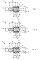
- Fig. 2 shows in a longitudinal section an exemplary racket 13.
- the racket 13 is in two parts from a cup-shaped base body 30 and an interior of the main body 30 completely filling insert 31 is formed.
- the base body 30 is preferably made of a steel
- the insert 31 is made of a material with a lower density than steel, for example a density less than 5.0 g / cm3.
- a preferred material for use are elastomers, eg, nitrile rubber (NBR), hydrogenated acrylonitrile-butadiene rubber (HNBR), fluoroaluminum (FPM, FKM).
- the insert 31 is formed without air pockets, in particular not as a foam, but its volume is completely filled by the material, whereby the insert 31 is incompressible.
- a surface 32 of the insert 31 facing the direction of impact 11 is exposed. All other sections of the surface of the insert 31, for example a surface 33 pointing in the direction of impact 11 , a lateral surface 34, touch an inner surface of the base body 30.
- a shape of the insert 31 is predetermined by a cavity 35 of the cup-shaped main body 30 . Neither the forces when striking the striker 16 nor the pressure during compression of the air spring deform the insert 31.
- the elastic construction of the insert 31 allows in a secure manner a complete filling of the cavity 35. Even small air bubbles between the insert 31 and the base body 30 can be avoided.
- the pot-shaped shape of the base body 30 includes an annular closed wall 36 which surrounds the cavity 35 circumferentially.
- a floor 37 adjoins the wall 36 in Impact direction 11 and closes the cavity 35 in the direction of impact 11.
- the single opening 38 of the cavity 35 thus points in a direction opposite to the direction of impact 11th
- the exemplary wall 36 may be formed by a hollow cylinder, ie with a cylindrical inner wall 39 and a coaxial cylindrical outer surface 40 .
- the outer surface 40 is guided along the working axis 10 on the inner surface 21 of the guide tube 20 at.
- a length 41 of the cylindrical portion 36, ie its dimension along the working axis 10, is preferably slightly larger than a diameter 42 of the base body 30.
- a ratio of length 41 to diameter 42 is for example in the range between 0.8 and 1.2, in order to prevent tilting of the racket 13 in the guide tube 20 .
- the outer surface 40 is preferably fully cylindrical, in an alternative embodiment composed of cylindrical segments.
- a wall thickness 43 of the wall 36 is, for example, in the range between 10% and 40% of the diameter 42 of the main body 30.
- the floor 37 may have a flat or curved inner surface 44 .
- a plunger 45 At the direction of impact 11 facing outside of the bottom 37 may be formed into a plunger 45 .
- the plunger 45 is essentially a full, cylindrical rod.
- the plunger 45 is thinner than the base body 30, and a diameter 46 of the plunger 45 is for example in the range between 30% and 50% of the diameter 42 of the base body 30 or bat 13.
- the diameter 46 is oriented on the diameter of the hammer drill 1 provided tools.
- the base body 30 may have a radial puncture in the wall 36 or a piercing in the bottom 37 , which allows the introduction of the insert 31, a leakage of air.
- a cross-sectional area of the puncture is smaller by at least an order of magnitude than an end face of the main body 30, for example less than 1 mm 2 or less than 1% of the cross-sectional area.
- the insert 31 contacts the entire inner surface 44 of the bottom 37 and the entire inner surface 39 of the wall 36.
- the exposed surface 46 of the insert 31 is preferably planar and terminates flush with the end 47 of the base body 30 .
- the entire rear surface of the racket 13 is preferably flat. For a given surface area of the end face, a distance between exciter 12 and racket 13 is a maximum at a predetermined pressure.
- An axial bore or a groove extending along the working axis 10 can be introduced into the insert 31 .
- the air can escape along this channel.
- the groove reduces the cross-sectional area of the insert 31 by less than 1%.
- the insert 31 can be fastened in the base body 30 in a form-fitting, material-locking and / or force-locking manner.
- a material closure can be achieved for example by gluing, pouring or vulcanizing.
- the illustrated insert 31 is inserted into the base body 30 and is clamped by a projection 48 on the inner surface 39 of the base body 30 .
- Fig. 3 shows a further embodiment of the racket 13.
- the insert 50 has an exposed back, opposite to the direction of impact 11 facing surface 51, which is convex, ie pointing away from the racket 13 , curved.
- the vault is small.
- An inclination of the surface 46 with respect to a plane perpendicular to the working axis 10 is in the range between 0 degrees and 10 degrees.
- a vertex 52 of the curvature preferably projects beyond the rear end 47 of the main body 30 by a distance 53 of less than 2 mm.
- the domed surface 51 preferably terminates flush with the rear end 47 .
- Fig. 4 shows a further embodiment of the racket 13.
- the insert 60 has an exposed back surface 61, which protrudes slightly beyond the rear end 47 of the base body 30 , without being flush with the ends 47 .
- An axial projection 62 of the insert 60 at the height of the wall 36 is less than 0.5 mm.
Landscapes
- Engineering & Computer Science (AREA)
- Mechanical Engineering (AREA)
- Percussive Tools And Related Accessories (AREA)
- Earth Drilling (AREA)
Claims (5)
- Machine-outil à main ayant un mécanisme de percussion pneumatique (6) qui comporte un excitateur entraîné par moteur (12), un tube de guidage (20) et un percuteur en forme de piston (13), dans laquelle le percuteur en forme de piston (13) est guidé par une surface intérieure (21) du tube de guidage (20) le long d'un axe de travail (10) et enferme, avec l'excitateur (12), un ressort pneumatique (15) dans le tube de guidage (20), dans laquelle le percuteur (13) est un corps de base en forme de cuvette (30) avec un espace creux ouvert dirigé vers l'excitateur et une pièce d'insertion (31, 50, 60) remplissant l'espace creux, dans laquelle le corps de base (30) est constitué d'un premier matériau ayant une première densité et la pièce d'insertion (31, 50, 60) est constituée d'un matériau ayant une seconde densité, et la première densité est supérieure à la seconde densité, dans laquelle le corps de base (30) entoure la pièce d'insertion (31, 50, 60) dans une direction radiale et dans une direction (11) opposée au ressort pneumatique (15), caractérisée en ce que la pièce d'insertion (31, 50) se termine de manière affleurante avec une extrémité (47) du corps de base (30) dirigée vers l'excitateur (12) ou en ce que la pièce d'insertion (31, 50) fait saillie à partir du corps de base (30) en direction de l'excitateur (12) de moins de 1 mm, et en ce que la pièce d'insertion (31, 50, 60) est formée d'un élastomère.
- Machine-outil à main selon la revendication 1, caractérisée en ce qu'une surface (32, 61), formée par le corps de base (30) et la pièce d'insertion (31, 50, 60) et dirigée vers l'excitateur (12), est plane.
- Machine-outil à main selon la revendication 2, caractérisée en ce qu'une surface (51) de la pièce d'insertion (50) dirigée vers l'excitateur (12) est inclinée de moins de 10 degrés par rapport à une direction radiale.
- Machine-outil à main selon l'une des revendications précédentes, caractérisée en ce que la pièce d'insertion (31, 50, 60) est réalisée de manière cylindrique et un diamètre de la pièce d'insertion (31, 50, 60) représente entre 50 % et 75 % d'un diamètre (42) du percuteur (13).
- Machine-outil à main selon l'une des revendications précédentes, caractérisée en ce qu'une portion de volume de la pièce d'insertion (31, 50, 60) sur le percuteur (13) est comprise entre 25 % et 75 %.
Applications Claiming Priority (1)
| Application Number | Priority Date | Filing Date | Title |
|---|---|---|---|
| DE201110075765 DE102011075765A1 (de) | 2011-05-12 | 2011-05-12 | Handwerkzeugmaschine |
Publications (2)
| Publication Number | Publication Date |
|---|---|
| EP2522467A1 EP2522467A1 (fr) | 2012-11-14 |
| EP2522467B1 true EP2522467B1 (fr) | 2015-06-03 |
Family
ID=46027607
Family Applications (1)
| Application Number | Title | Priority Date | Filing Date |
|---|---|---|---|
| EP12163528.8A Active EP2522467B1 (fr) | 2011-05-12 | 2012-04-10 | Machine-outil manuelle |
Country Status (4)
| Country | Link |
|---|---|
| US (1) | US9102044B2 (fr) |
| EP (1) | EP2522467B1 (fr) |
| CN (1) | CN102773842B (fr) |
| DE (1) | DE102011075765A1 (fr) |
Families Citing this family (11)
| Publication number | Priority date | Publication date | Assignee | Title |
|---|---|---|---|---|
| EP2910336A1 (fr) * | 2014-02-21 | 2015-08-26 | HILTI Aktiengesellschaft | Machine-outil portative |
| EP3034242A1 (fr) * | 2014-12-18 | 2016-06-22 | HILTI Aktiengesellschaft | Machine-outil manuelle |
| EP3117962A1 (fr) * | 2015-07-17 | 2017-01-18 | HILTI Aktiengesellschaft | Machine-outil portative |
| EP3260239A1 (fr) * | 2016-06-24 | 2017-12-27 | HILTI Aktiengesellschaft | Machine-outil portative |
| DE102017209829A1 (de) | 2017-06-12 | 2018-12-13 | Robert Bosch Gmbh | Handwerkzeugmaschine |
| EP3670097A1 (fr) * | 2018-12-21 | 2020-06-24 | Hilti Aktiengesellschaft | Machine-outil portative |
| JP6710419B1 (ja) * | 2019-05-22 | 2020-06-17 | 新シコー科技株式会社 | 光学素子駆動装置、カメラ装置、及び電子機器 |
| EP3822036A1 (fr) * | 2019-11-12 | 2021-05-19 | Hilti Aktiengesellschaft | Agencement de mécanisme de frappe |
| WO2022031641A1 (fr) * | 2020-08-03 | 2022-02-10 | Milwaukee Electric Tool Corporation | Mécanisme d'impact doté d'un percuteur multi-matériau |
| CN116352658A (zh) * | 2021-12-20 | 2023-06-30 | 南京泉峰科技有限公司 | 电动工具及锤钻 |
| EP4427885A1 (fr) * | 2023-03-07 | 2024-09-11 | Hilti Aktiengesellschaft | Procédé de fabrication d'un corps de percussion hybride pour un outil électrique à main |
Citations (1)
| Publication number | Priority date | Publication date | Assignee | Title |
|---|---|---|---|---|
| DE10356928A1 (de) * | 2003-12-05 | 2005-06-30 | Robert Bosch Gmbh | Schlagwerk, Kolbenvorrichtung und Werkzeugmaschine |
Family Cites Families (8)
| Publication number | Priority date | Publication date | Assignee | Title |
|---|---|---|---|---|
| US1167975A (en) * | 1914-05-21 | 1916-01-11 | Engineering Products Corp | Pneumatic-tool piston. |
| US2694383A (en) | 1948-04-08 | 1954-11-16 | Atlas Diesel Ab | Pressure fluid driven hammer piston for hammer drills and other percussion tools |
| DE2726214A1 (de) * | 1977-06-10 | 1978-12-21 | Hilti Ag | Bohrhammer mit pneumatisch angetriebenem schlagkolben |
| DE19646381A1 (de) | 1996-11-11 | 1998-05-14 | Hilti Ag | Handgerät |
| JP2006123025A (ja) * | 2004-10-26 | 2006-05-18 | Matsushita Electric Works Ltd | 衝撃工具 |
| DE102007000393A1 (de) * | 2007-07-19 | 2009-01-22 | Hilti Aktiengesellschaft | Handwerkzeugmaschine mit pneumatischem Schlagwerk |
| CN101444909B (zh) | 2007-11-27 | 2013-03-27 | 希尔蒂股份公司 | 具有气动冲击装置的手持式工具机 |
| CN101949260B (zh) * | 2010-07-22 | 2013-07-24 | 浙江师范大学 | 一种储能后释放的冲击锤的辅锤机构及储能式冲击锤 |
-
2011
- 2011-05-12 DE DE201110075765 patent/DE102011075765A1/de not_active Ceased
-
2012
- 2012-04-10 EP EP12163528.8A patent/EP2522467B1/fr active Active
- 2012-05-09 CN CN201210141496.5A patent/CN102773842B/zh active Active
- 2012-05-11 US US13/469,617 patent/US9102044B2/en active Active
Patent Citations (1)
| Publication number | Priority date | Publication date | Assignee | Title |
|---|---|---|---|---|
| DE10356928A1 (de) * | 2003-12-05 | 2005-06-30 | Robert Bosch Gmbh | Schlagwerk, Kolbenvorrichtung und Werkzeugmaschine |
Also Published As
| Publication number | Publication date |
|---|---|
| DE102011075765A1 (de) | 2012-11-15 |
| CN102773842A (zh) | 2012-11-14 |
| US9102044B2 (en) | 2015-08-11 |
| CN102773842B (zh) | 2016-08-24 |
| EP2522467A1 (fr) | 2012-11-14 |
| US20120298393A1 (en) | 2012-11-29 |
Similar Documents
| Publication | Publication Date | Title |
|---|---|---|
| EP2522467B1 (fr) | Machine-outil manuelle | |
| EP2653270B1 (fr) | Machine-outil portative | |
| DE102009026542A1 (de) | Werkzeugmaschine | |
| EP1716979B1 (fr) | Marteau perforateur ou marteau-burineur | |
| EP3442753B1 (fr) | Machine-outil portative | |
| EP2684646B1 (fr) | Machine-outil manuelle | |
| EP3140081B1 (fr) | Machine-outil portative | |
| EP3181301A1 (fr) | Machine-outil portative a percussion | |
| EP1355764B1 (fr) | Outil de percussion pneumatique comportant un piston d'entrainement de longueur reduite | |
| DE2437023A1 (de) | Schlag- oder drehschlaghammer | |
| DE102007035699A1 (de) | Handwerkzeugmaschine | |
| EP2919946B1 (fr) | Machine-outil | |
| DE19929183A1 (de) | Luftfederschlagwerk mit hohlem Schlagkolben | |
| DE3633675A1 (de) | Bohrhammer mit schlagwerk | |
| EP3389934B1 (fr) | Machine-outil portative a percussion | |
| EP1910039B1 (fr) | Mécanisme de percussion pour un outil portatif utilisé au moins en percussion | |
| EP0218547B1 (fr) | Marteau pour forer ou buriner | |
| DE2726214A1 (de) | Bohrhammer mit pneumatisch angetriebenem schlagkolben | |
| EP2540452A1 (fr) | Mécanisme de percussion pneumatique avec volumes d'amortisseur pneumatique séparés | |
| DE102006046472A1 (de) | Schlagvorrichtung | |
| DE2605998C3 (de) | Bohrhammer mit in einem Zylinder untergebrachten Antriebs- und Schlagelementen | |
| DE102011084465A1 (de) | Flugkolben | |
| DE102012201952A1 (de) | Pneumatische Schlagwerkvorrichtung | |
| DE102009045656A1 (de) | Werkzeugvorrichtung | |
| DE7718338U1 (de) | Bohrhammer mit pneumatisch angetriebenem schlagkolben |
Legal Events
| Date | Code | Title | Description |
|---|---|---|---|
| PUAI | Public reference made under article 153(3) epc to a published international application that has entered the european phase |
Free format text: ORIGINAL CODE: 0009012 |
|
| AK | Designated contracting states |
Kind code of ref document: A1 Designated state(s): AL AT BE BG CH CY CZ DE DK EE ES FI FR GB GR HR HU IE IS IT LI LT LU LV MC MK MT NL NO PL PT RO RS SE SI SK SM TR |
|
| AX | Request for extension of the european patent |
Extension state: BA ME |
|
| 17P | Request for examination filed |
Effective date: 20130514 |
|
| GRAP | Despatch of communication of intention to grant a patent |
Free format text: ORIGINAL CODE: EPIDOSNIGR1 |
|
| INTG | Intention to grant announced |
Effective date: 20150317 |
|
| GRAS | Grant fee paid |
Free format text: ORIGINAL CODE: EPIDOSNIGR3 |
|
| GRAA | (expected) grant |
Free format text: ORIGINAL CODE: 0009210 |
|
| AK | Designated contracting states |
Kind code of ref document: B1 Designated state(s): AL AT BE BG CH CY CZ DE DK EE ES FI FR GB GR HR HU IE IS IT LI LT LU LV MC MK MT NL NO PL PT RO RS SE SI SK SM TR |
|
| REG | Reference to a national code |
Ref country code: GB Ref legal event code: FG4D Free format text: NOT ENGLISH |
|
| REG | Reference to a national code |
Ref country code: CH Ref legal event code: EP |
|
| REG | Reference to a national code |
Ref country code: AT Ref legal event code: REF Ref document number: 729670 Country of ref document: AT Kind code of ref document: T Effective date: 20150715 Ref country code: IE Ref legal event code: FG4D Free format text: LANGUAGE OF EP DOCUMENT: GERMAN |
|
| REG | Reference to a national code |
Ref country code: DE Ref legal event code: R096 Ref document number: 502012003329 Country of ref document: DE |
|
| PG25 | Lapsed in a contracting state [announced via postgrant information from national office to epo] |
Ref country code: ES Free format text: LAPSE BECAUSE OF FAILURE TO SUBMIT A TRANSLATION OF THE DESCRIPTION OR TO PAY THE FEE WITHIN THE PRESCRIBED TIME-LIMIT Effective date: 20150603 Ref country code: FI Free format text: LAPSE BECAUSE OF FAILURE TO SUBMIT A TRANSLATION OF THE DESCRIPTION OR TO PAY THE FEE WITHIN THE PRESCRIBED TIME-LIMIT Effective date: 20150603 Ref country code: NO Free format text: LAPSE BECAUSE OF FAILURE TO SUBMIT A TRANSLATION OF THE DESCRIPTION OR TO PAY THE FEE WITHIN THE PRESCRIBED TIME-LIMIT Effective date: 20150903 Ref country code: HR Free format text: LAPSE BECAUSE OF FAILURE TO SUBMIT A TRANSLATION OF THE DESCRIPTION OR TO PAY THE FEE WITHIN THE PRESCRIBED TIME-LIMIT Effective date: 20150603 Ref country code: LT Free format text: LAPSE BECAUSE OF FAILURE TO SUBMIT A TRANSLATION OF THE DESCRIPTION OR TO PAY THE FEE WITHIN THE PRESCRIBED TIME-LIMIT Effective date: 20150603 |
|
| REG | Reference to a national code |
Ref country code: NL Ref legal event code: MP Effective date: 20150603 |
|
| REG | Reference to a national code |
Ref country code: LT Ref legal event code: MG4D |
|
| PG25 | Lapsed in a contracting state [announced via postgrant information from national office to epo] |
Ref country code: GR Free format text: LAPSE BECAUSE OF FAILURE TO SUBMIT A TRANSLATION OF THE DESCRIPTION OR TO PAY THE FEE WITHIN THE PRESCRIBED TIME-LIMIT Effective date: 20150904 Ref country code: RS Free format text: LAPSE BECAUSE OF FAILURE TO SUBMIT A TRANSLATION OF THE DESCRIPTION OR TO PAY THE FEE WITHIN THE PRESCRIBED TIME-LIMIT Effective date: 20150603 Ref country code: BG Free format text: LAPSE BECAUSE OF FAILURE TO SUBMIT A TRANSLATION OF THE DESCRIPTION OR TO PAY THE FEE WITHIN THE PRESCRIBED TIME-LIMIT Effective date: 20150903 Ref country code: LV Free format text: LAPSE BECAUSE OF FAILURE TO SUBMIT A TRANSLATION OF THE DESCRIPTION OR TO PAY THE FEE WITHIN THE PRESCRIBED TIME-LIMIT Effective date: 20150603 |
|
| PG25 | Lapsed in a contracting state [announced via postgrant information from national office to epo] |
Ref country code: EE Free format text: LAPSE BECAUSE OF FAILURE TO SUBMIT A TRANSLATION OF THE DESCRIPTION OR TO PAY THE FEE WITHIN THE PRESCRIBED TIME-LIMIT Effective date: 20150603 |
|
| PG25 | Lapsed in a contracting state [announced via postgrant information from national office to epo] |
Ref country code: PL Free format text: LAPSE BECAUSE OF FAILURE TO SUBMIT A TRANSLATION OF THE DESCRIPTION OR TO PAY THE FEE WITHIN THE PRESCRIBED TIME-LIMIT Effective date: 20150603 Ref country code: RO Free format text: LAPSE BECAUSE OF NON-PAYMENT OF DUE FEES Effective date: 20150603 Ref country code: SK Free format text: LAPSE BECAUSE OF FAILURE TO SUBMIT A TRANSLATION OF THE DESCRIPTION OR TO PAY THE FEE WITHIN THE PRESCRIBED TIME-LIMIT Effective date: 20150603 Ref country code: CZ Free format text: LAPSE BECAUSE OF FAILURE TO SUBMIT A TRANSLATION OF THE DESCRIPTION OR TO PAY THE FEE WITHIN THE PRESCRIBED TIME-LIMIT Effective date: 20150603 Ref country code: IS Free format text: LAPSE BECAUSE OF FAILURE TO SUBMIT A TRANSLATION OF THE DESCRIPTION OR TO PAY THE FEE WITHIN THE PRESCRIBED TIME-LIMIT Effective date: 20151003 Ref country code: PT Free format text: LAPSE BECAUSE OF FAILURE TO SUBMIT A TRANSLATION OF THE DESCRIPTION OR TO PAY THE FEE WITHIN THE PRESCRIBED TIME-LIMIT Effective date: 20151006 |
|
| REG | Reference to a national code |
Ref country code: DE Ref legal event code: R097 Ref document number: 502012003329 Country of ref document: DE |
|
| REG | Reference to a national code |
Ref country code: FR Ref legal event code: PLFP Year of fee payment: 5 |
|
| PLBE | No opposition filed within time limit |
Free format text: ORIGINAL CODE: 0009261 |
|
| STAA | Information on the status of an ep patent application or granted ep patent |
Free format text: STATUS: NO OPPOSITION FILED WITHIN TIME LIMIT |
|
| PG25 | Lapsed in a contracting state [announced via postgrant information from national office to epo] |
Ref country code: IT Free format text: LAPSE BECAUSE OF FAILURE TO SUBMIT A TRANSLATION OF THE DESCRIPTION OR TO PAY THE FEE WITHIN THE PRESCRIBED TIME-LIMIT Effective date: 20150603 Ref country code: DK Free format text: LAPSE BECAUSE OF FAILURE TO SUBMIT A TRANSLATION OF THE DESCRIPTION OR TO PAY THE FEE WITHIN THE PRESCRIBED TIME-LIMIT Effective date: 20150603 |
|
| 26N | No opposition filed |
Effective date: 20160304 |
|
| PG25 | Lapsed in a contracting state [announced via postgrant information from national office to epo] |
Ref country code: SI Free format text: LAPSE BECAUSE OF FAILURE TO SUBMIT A TRANSLATION OF THE DESCRIPTION OR TO PAY THE FEE WITHIN THE PRESCRIBED TIME-LIMIT Effective date: 20150603 |
|
| PG25 | Lapsed in a contracting state [announced via postgrant information from national office to epo] |
Ref country code: BE Free format text: LAPSE BECAUSE OF NON-PAYMENT OF DUE FEES Effective date: 20160430 |
|
| REG | Reference to a national code |
Ref country code: CH Ref legal event code: PL |
|
| PG25 | Lapsed in a contracting state [announced via postgrant information from national office to epo] |
Ref country code: LU Free format text: LAPSE BECAUSE OF FAILURE TO SUBMIT A TRANSLATION OF THE DESCRIPTION OR TO PAY THE FEE WITHIN THE PRESCRIBED TIME-LIMIT Effective date: 20160410 |
|
| REG | Reference to a national code |
Ref country code: IE Ref legal event code: MM4A |
|
| PG25 | Lapsed in a contracting state [announced via postgrant information from national office to epo] |
Ref country code: LI Free format text: LAPSE BECAUSE OF NON-PAYMENT OF DUE FEES Effective date: 20160430 Ref country code: CH Free format text: LAPSE BECAUSE OF NON-PAYMENT OF DUE FEES Effective date: 20160430 |
|
| REG | Reference to a national code |
Ref country code: FR Ref legal event code: PLFP Year of fee payment: 6 |
|
| PG25 | Lapsed in a contracting state [announced via postgrant information from national office to epo] |
Ref country code: IE Free format text: LAPSE BECAUSE OF NON-PAYMENT OF DUE FEES Effective date: 20160410 |
|
| PG25 | Lapsed in a contracting state [announced via postgrant information from national office to epo] |
Ref country code: NL Free format text: LAPSE BECAUSE OF FAILURE TO SUBMIT A TRANSLATION OF THE DESCRIPTION OR TO PAY THE FEE WITHIN THE PRESCRIBED TIME-LIMIT Effective date: 20150603 Ref country code: SE Free format text: LAPSE BECAUSE OF FAILURE TO SUBMIT A TRANSLATION OF THE DESCRIPTION OR TO PAY THE FEE WITHIN THE PRESCRIBED TIME-LIMIT Effective date: 20150603 |
|
| REG | Reference to a national code |
Ref country code: FR Ref legal event code: PLFP Year of fee payment: 7 |
|
| PG25 | Lapsed in a contracting state [announced via postgrant information from national office to epo] |
Ref country code: HU Free format text: LAPSE BECAUSE OF FAILURE TO SUBMIT A TRANSLATION OF THE DESCRIPTION OR TO PAY THE FEE WITHIN THE PRESCRIBED TIME-LIMIT; INVALID AB INITIO Effective date: 20120410 Ref country code: CY Free format text: LAPSE BECAUSE OF FAILURE TO SUBMIT A TRANSLATION OF THE DESCRIPTION OR TO PAY THE FEE WITHIN THE PRESCRIBED TIME-LIMIT Effective date: 20150603 Ref country code: SM Free format text: LAPSE BECAUSE OF FAILURE TO SUBMIT A TRANSLATION OF THE DESCRIPTION OR TO PAY THE FEE WITHIN THE PRESCRIBED TIME-LIMIT Effective date: 20150603 |
|
| REG | Reference to a national code |
Ref country code: AT Ref legal event code: MM01 Ref document number: 729670 Country of ref document: AT Kind code of ref document: T Effective date: 20170410 |
|
| PG25 | Lapsed in a contracting state [announced via postgrant information from national office to epo] |
Ref country code: TR Free format text: LAPSE BECAUSE OF FAILURE TO SUBMIT A TRANSLATION OF THE DESCRIPTION OR TO PAY THE FEE WITHIN THE PRESCRIBED TIME-LIMIT Effective date: 20150603 Ref country code: MK Free format text: LAPSE BECAUSE OF FAILURE TO SUBMIT A TRANSLATION OF THE DESCRIPTION OR TO PAY THE FEE WITHIN THE PRESCRIBED TIME-LIMIT Effective date: 20150603 Ref country code: MT Free format text: LAPSE BECAUSE OF FAILURE TO SUBMIT A TRANSLATION OF THE DESCRIPTION OR TO PAY THE FEE WITHIN THE PRESCRIBED TIME-LIMIT Effective date: 20150603 Ref country code: MC Free format text: LAPSE BECAUSE OF FAILURE TO SUBMIT A TRANSLATION OF THE DESCRIPTION OR TO PAY THE FEE WITHIN THE PRESCRIBED TIME-LIMIT Effective date: 20150603 |
|
| PG25 | Lapsed in a contracting state [announced via postgrant information from national office to epo] |
Ref country code: AT Free format text: LAPSE BECAUSE OF NON-PAYMENT OF DUE FEES Effective date: 20170410 |
|
| PG25 | Lapsed in a contracting state [announced via postgrant information from national office to epo] |
Ref country code: AL Free format text: LAPSE BECAUSE OF FAILURE TO SUBMIT A TRANSLATION OF THE DESCRIPTION OR TO PAY THE FEE WITHIN THE PRESCRIBED TIME-LIMIT Effective date: 20150603 |
|
| P01 | Opt-out of the competence of the unified patent court (upc) registered |
Effective date: 20230830 |
|
| PGFP | Annual fee paid to national office [announced via postgrant information from national office to epo] |
Ref country code: DE Payment date: 20250422 Year of fee payment: 14 |
|
| PGFP | Annual fee paid to national office [announced via postgrant information from national office to epo] |
Ref country code: GB Payment date: 20250423 Year of fee payment: 14 |
|
| PGFP | Annual fee paid to national office [announced via postgrant information from national office to epo] |
Ref country code: FR Payment date: 20250425 Year of fee payment: 14 |