EP2522484B1 - Dispositif et procédé de déformation d'ébauches en plastique en conteneurs en plastique dotés d'un verrouillage à actionnement magnétique - Google Patents
Dispositif et procédé de déformation d'ébauches en plastique en conteneurs en plastique dotés d'un verrouillage à actionnement magnétique Download PDFInfo
- Publication number
- EP2522484B1 EP2522484B1 EP12167262.0A EP12167262A EP2522484B1 EP 2522484 B1 EP2522484 B1 EP 2522484B1 EP 12167262 A EP12167262 A EP 12167262A EP 2522484 B1 EP2522484 B1 EP 2522484B1
- Authority
- EP
- European Patent Office
- Prior art keywords
- blow mould
- locking element
- blow
- locking
- magnetic
- Prior art date
- Legal status (The legal status is an assumption and is not a legal conclusion. Google has not performed a legal analysis and makes no representation as to the accuracy of the status listed.)
- Not-in-force
Links
- 229920003023 plastic Polymers 0.000 title claims description 36
- 239000004033 plastic Substances 0.000 title claims description 36
- 238000000034 method Methods 0.000 title claims description 11
- 230000008569 process Effects 0.000 title description 7
- 238000000071 blow moulding Methods 0.000 claims description 13
- 230000007246 mechanism Effects 0.000 claims description 13
- 230000003993 interaction Effects 0.000 claims description 3
- 239000000463 material Substances 0.000 claims 6
- 238000007493 shaping process Methods 0.000 claims 2
- 238000007664 blowing Methods 0.000 description 43
- 230000001954 sterilising effect Effects 0.000 description 15
- 238000004659 sterilization and disinfection Methods 0.000 description 13
- 238000010438 heat treatment Methods 0.000 description 5
- MHAJPDPJQMAIIY-UHFFFAOYSA-N Hydrogen peroxide Chemical compound OO MHAJPDPJQMAIIY-UHFFFAOYSA-N 0.000 description 4
- 238000007789 sealing Methods 0.000 description 4
- 230000008901 benefit Effects 0.000 description 3
- 239000000969 carrier Substances 0.000 description 2
- 238000006243 chemical reaction Methods 0.000 description 2
- 230000005672 electromagnetic field Effects 0.000 description 2
- 239000007789 gas Substances 0.000 description 2
- 238000004519 manufacturing process Methods 0.000 description 2
- 230000009466 transformation Effects 0.000 description 2
- XLYOFNOQVPJJNP-UHFFFAOYSA-N water Substances O XLYOFNOQVPJJNP-UHFFFAOYSA-N 0.000 description 2
- 230000003213 activating effect Effects 0.000 description 1
- 230000004913 activation Effects 0.000 description 1
- 235000013361 beverage Nutrition 0.000 description 1
- 230000015572 biosynthetic process Effects 0.000 description 1
- 230000001419 dependent effect Effects 0.000 description 1
- 238000011161 development Methods 0.000 description 1
- 230000018109 developmental process Effects 0.000 description 1
- 238000006073 displacement reaction Methods 0.000 description 1
- 230000000694 effects Effects 0.000 description 1
- 230000005670 electromagnetic radiation Effects 0.000 description 1
- 238000005265 energy consumption Methods 0.000 description 1
- 230000036512 infertility Effects 0.000 description 1
- 239000012212 insulator Substances 0.000 description 1
- 230000005415 magnetization Effects 0.000 description 1
- 230000001681 protective effect Effects 0.000 description 1
- 239000003206 sterilizing agent Substances 0.000 description 1
- 238000009423 ventilation Methods 0.000 description 1
Images

Classifications
-
- B—PERFORMING OPERATIONS; TRANSPORTING
- B29—WORKING OF PLASTICS; WORKING OF SUBSTANCES IN A PLASTIC STATE IN GENERAL
- B29C—SHAPING OR JOINING OF PLASTICS; SHAPING OF MATERIAL IN A PLASTIC STATE, NOT OTHERWISE PROVIDED FOR; AFTER-TREATMENT OF THE SHAPED PRODUCTS, e.g. REPAIRING
- B29C49/00—Blow-moulding, i.e. blowing a preform or parison to a desired shape within a mould; Apparatus therefor
- B29C49/42—Component parts, details or accessories; Auxiliary operations
- B29C49/56—Opening, closing or clamping means
- B29C49/5601—Mechanically operated, i.e. closing or opening of the mould parts is done by mechanic means
- B29C49/5602—Mechanically operated, i.e. closing or opening of the mould parts is done by mechanic means using cams
-
- B—PERFORMING OPERATIONS; TRANSPORTING
- B29—WORKING OF PLASTICS; WORKING OF SUBSTANCES IN A PLASTIC STATE IN GENERAL
- B29C—SHAPING OR JOINING OF PLASTICS; SHAPING OF MATERIAL IN A PLASTIC STATE, NOT OTHERWISE PROVIDED FOR; AFTER-TREATMENT OF THE SHAPED PRODUCTS, e.g. REPAIRING
- B29C49/00—Blow-moulding, i.e. blowing a preform or parison to a desired shape within a mould; Apparatus therefor
- B29C49/42—Component parts, details or accessories; Auxiliary operations
- B29C49/48—Moulds
- B29C2049/4879—Moulds characterised by mould configurations
- B29C2049/4892—Mould halves consisting of an independent main and bottom part
-
- B—PERFORMING OPERATIONS; TRANSPORTING
- B29—WORKING OF PLASTICS; WORKING OF SUBSTANCES IN A PLASTIC STATE IN GENERAL
- B29C—SHAPING OR JOINING OF PLASTICS; SHAPING OF MATERIAL IN A PLASTIC STATE, NOT OTHERWISE PROVIDED FOR; AFTER-TREATMENT OF THE SHAPED PRODUCTS, e.g. REPAIRING
- B29C49/00—Blow-moulding, i.e. blowing a preform or parison to a desired shape within a mould; Apparatus therefor
- B29C49/42—Component parts, details or accessories; Auxiliary operations
- B29C49/56—Opening, closing or clamping means
- B29C2049/566—Locking means
-
- B—PERFORMING OPERATIONS; TRANSPORTING
- B29—WORKING OF PLASTICS; WORKING OF SUBSTANCES IN A PLASTIC STATE IN GENERAL
- B29C—SHAPING OR JOINING OF PLASTICS; SHAPING OF MATERIAL IN A PLASTIC STATE, NOT OTHERWISE PROVIDED FOR; AFTER-TREATMENT OF THE SHAPED PRODUCTS, e.g. REPAIRING
- B29C49/00—Blow-moulding, i.e. blowing a preform or parison to a desired shape within a mould; Apparatus therefor
- B29C49/42—Component parts, details or accessories; Auxiliary operations
- B29C49/56—Opening, closing or clamping means
- B29C2049/566—Locking means
- B29C2049/5661—Mechanical
-
- B—PERFORMING OPERATIONS; TRANSPORTING
- B29—WORKING OF PLASTICS; WORKING OF SUBSTANCES IN A PLASTIC STATE IN GENERAL
- B29C—SHAPING OR JOINING OF PLASTICS; SHAPING OF MATERIAL IN A PLASTIC STATE, NOT OTHERWISE PROVIDED FOR; AFTER-TREATMENT OF THE SHAPED PRODUCTS, e.g. REPAIRING
- B29C49/00—Blow-moulding, i.e. blowing a preform or parison to a desired shape within a mould; Apparatus therefor
- B29C49/42—Component parts, details or accessories; Auxiliary operations
- B29C49/56—Opening, closing or clamping means
- B29C2049/566—Locking means
- B29C2049/5665—Magnetic
-
- B—PERFORMING OPERATIONS; TRANSPORTING
- B29—WORKING OF PLASTICS; WORKING OF SUBSTANCES IN A PLASTIC STATE IN GENERAL
- B29C—SHAPING OR JOINING OF PLASTICS; SHAPING OF MATERIAL IN A PLASTIC STATE, NOT OTHERWISE PROVIDED FOR; AFTER-TREATMENT OF THE SHAPED PRODUCTS, e.g. REPAIRING
- B29C2949/00—Indexing scheme relating to blow-moulding
- B29C2949/07—Preforms or parisons characterised by their configuration
- B29C2949/0715—Preforms or parisons characterised by their configuration the preform having one end closed
-
- B—PERFORMING OPERATIONS; TRANSPORTING
- B29—WORKING OF PLASTICS; WORKING OF SUBSTANCES IN A PLASTIC STATE IN GENERAL
- B29C—SHAPING OR JOINING OF PLASTICS; SHAPING OF MATERIAL IN A PLASTIC STATE, NOT OTHERWISE PROVIDED FOR; AFTER-TREATMENT OF THE SHAPED PRODUCTS, e.g. REPAIRING
- B29C49/00—Blow-moulding, i.e. blowing a preform or parison to a desired shape within a mould; Apparatus therefor
- B29C49/02—Combined blow-moulding and manufacture of the preform or the parison
- B29C49/06—Injection blow-moulding
-
- B—PERFORMING OPERATIONS; TRANSPORTING
- B29—WORKING OF PLASTICS; WORKING OF SUBSTANCES IN A PLASTIC STATE IN GENERAL
- B29C—SHAPING OR JOINING OF PLASTICS; SHAPING OF MATERIAL IN A PLASTIC STATE, NOT OTHERWISE PROVIDED FOR; AFTER-TREATMENT OF THE SHAPED PRODUCTS, e.g. REPAIRING
- B29C49/00—Blow-moulding, i.e. blowing a preform or parison to a desired shape within a mould; Apparatus therefor
- B29C49/28—Blow-moulding apparatus
- B29C49/30—Blow-moulding apparatus having movable moulds or mould parts
- B29C49/36—Blow-moulding apparatus having movable moulds or mould parts rotatable about one axis
-
- B—PERFORMING OPERATIONS; TRANSPORTING
- B29—WORKING OF PLASTICS; WORKING OF SUBSTANCES IN A PLASTIC STATE IN GENERAL
- B29C—SHAPING OR JOINING OF PLASTICS; SHAPING OF MATERIAL IN A PLASTIC STATE, NOT OTHERWISE PROVIDED FOR; AFTER-TREATMENT OF THE SHAPED PRODUCTS, e.g. REPAIRING
- B29C49/00—Blow-moulding, i.e. blowing a preform or parison to a desired shape within a mould; Apparatus therefor
- B29C49/42—Component parts, details or accessories; Auxiliary operations
- B29C49/56—Opening, closing or clamping means
- B29C49/561—Characterised by speed, e.g. variable opening closing speed
Definitions
- the present invention relates to an apparatus for forming plastic preforms into plastic containers.
- Such devices have been known for a long time from the prior art.
- heated plastic preforms are usually expanded by means of a gaseous medium and in particular by means of compressed air to plastic containers.
- the plastic preforms are introduced into a blow mold and then acted upon in particular via its mouth with compressed air. This means that during the expansion process, the blow mold is subjected to considerable forces. Therefore, it is also known from the prior art to provide a locking mechanism which locks the blow mold halves together at least during the expansion process.
- guide curves are provided in the prior art, along which run guide rollers, which is moved by this movement, a locking element.
- an electrically operated blow molding machine and a corresponding blow molding process are known. In this machine, an electric motor drive for driving the locking elements is provided.
- DE102009007717 A discloses an apparatus and a method for forming plastic preforms into plastic containers, wherein there is a magnetic element included in a guide element that is used on a guide curve, wherein the guide curve may be a locking curve of a mold carrier.
- the present invention has for its object to simplify the known from the prior art locking mechanisms, for example, to be able to dispense with the lubricated rollers usually required in the art.
- This is inventively achieved by a device according to claim 1 and a method according to claim 9.
- Advantageous embodiments and further developments are the subject of the dependent claims.
- a device according to the invention for forming plastic preforms into plastic containers is defined in claim 1. It is proposed according to the invention to provide, with the aid of an at least temporary magnetic element, for example an electromagnet, a contactless and thus frictionless, maintenance-free solution in order to effect the locking of the blow mold.
- the first locking element is pivotable with respect to a predetermined pivot axis.
- a maximum pivot angle of the first locking element between 3 ° and 40 °, preferably between 5 ° and 35 ° and particularly preferably between 5 ° and 30 °.
- This second pivot axis, with respect to which the first locking element is pivotable preferably extends substantially parallel to the pivot axis about which the Blasformamba is pivotable. Substantially parallel is understood to mean that a tilt angle between these two pivot axes is smaller in magnitude than 15 °, preferably smaller than 10 °, preferably smaller than 5 °.
- the magnetic element is arranged stationarily opposite the blowing station, for example on a stationary support. It is possible that the magnetic element is activated in each case if the locking element to be moved to lock. However, the magnetic element can also be permanently activated during operation. However, it is also conceivable that the magnetic element moves with the blowing station and is activated in each case when the blowing station is to be locked.
- the magnetic element has an electromagnet.
- a second magnetic element is provided on the blowing station, which temporarily holds the locking element in a locking position.
- This second magnetic element can serve as a backup to ensure the locking state of the blow mold.
- a mechanically acting locking means is provided, which maintains a locking state.
- this second magnetic element is a permanent magnet.
- This second magnetic element advantageously moves with the blowing station and is particularly preferably arranged stationarily on one of the blow molded carrier parts.
- a third magnetic element is provided, which holds the locking element at least temporarily in an unlocked position.
- this third magnetic element can be prevented that the locking mechanism inadvertently goes into a locked state and in this way, for example, blockages of the blowing station can occur.
- the device has a particularly stationary arranged movement generating element which moves the locking element.
- the locking element is moved by a mechanical contact.
- This movement generating element advantageously serves as a securing mechanism, if the magnetic locking mechanism should fail.
- this movement generating element is advantageously arranged at a position which is arranged downstream of the magnetic element in the direction of movement of the blowing station or in a position in which the locking would already be completed in error-free operation. This advantageously comes this movement generating element only used when the lock has not been properly closed by the magnetic element. As a rule, therefore, there is no intervention of the movement-generating element.
- the device has another movement generating element which unlocks the locking mechanism if a corresponding magnetic unlocking fails.
- the device has a second at least temporarily magnetic element, with respect to which the first locking element is movable and which causes a movement of the first locking element for unlocking the Blasformaniimaschinener by a magnetic interaction. It is therefore proposed that the unlocking of the blowing station or the blow mold carrier takes place in a magnetic and thus in particular contactless manner.
- the first magnetic element and a fourth magnetic element are arranged at different locations along the movement path of the blowing station. This is due to the fact that also the opening and closing of the blowing station and also the locking and unlocking take place at different positions of the blowing station with respect to their transport path.
- the device has a clean room, within which the blowing station is transported, wherein advantageously this clean room is separated by means of at least one wall with respect to an environment or arranged separately.
- a channel-like clean room is provided, which surrounds the blowing station.
- a plurality of advantageously identical blowing stations is arranged on the movable support. These blowing stations are advantageously all promoted by the said clean room.
- at least one wall also forms a wall bounding the clean room.
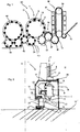
- FIG. 1 shows a schematic representation of a plant for producing plastic containers.
- This system 50 has a heating device 30 in which plastic preforms 10 are heated.
- these plastic preforms 10 are guided by means of a transport device 34, such as a revolving chain, through this heater 30 and thereby heated with a plurality of heating elements 31.
- This heating device 30 is followed by a transfer unit 36, which transfers the preforms 10 to a sterilization device 32.
- This sterilization device 32 in this case likewise has a transport wheel 37 and sterilizing elements can be arranged on this transport wheel 37 or even stationary. In this area, for example, a sterilization by hydrogen peroxide gas or by electromagnetic radiation is possible. In particular, an internal sterilization of the preforms is carried out in this area.
- the reference numeral 20 denotes in its entirety a clean room, the outer boundaries are indicated here by the dotted line L.
- the clean room 20 is arranged not only in the area of the transport wheel 2 and the filling device 40, but possibly already starts in the area of the heating device 30, the sterilization device 32, the plastic preform feed and / or the plastic preform production. It can be seen that this clean room 20 begins in the area of the sterilization unit 32. In this area, lock devices can be provided to introduce the plastic preforms into the clean room 20 without too much gas flowing inside the clean room and thus being lost.
- the clean room is, as indicated by the dashed line L, adapted to the outer shape of the individual plant components. In this way, the volume of the clean room can be reduced.
- Reference numeral 1 designates in its entirety a forming device in which a plurality of blowing stations or forming stations 8 is arranged on a transport wheel 2, wherein only one of these blowing stations 8 is shown here. With these blowing stations 8, the plastic preforms 10 are expanded to containers 10a. Although not shown in detail here, not the entire area of the transport device 2 is located within the clean room 20, but the clean room 20 or insulator is effectively implemented as a mini-isolator within the entire device. Thus, it would be possible for the clean room to be channel-like, at least in the area of the forming device 1.
- the reference numeral 22 refers to a feeding device which transfers the preforms to the forming device 1 and the reference numeral 24 to a discharge device which discharges the produced plastic containers 10a from the forming device 1. It can be seen that the clean room 20 in the area of the feed device 22 and the discharge device 24 each have recesses which receive these devices 22, 24. In this way, a transfer of the plastic preforms 10 to the forming device 1 and a takeover of the plastic containers 10a of the forming device 1 can be achieved in a particularly advantageous manner. With a transfer unit 42, the expanded plastic containers are transferred to a filling device 40 and then discharged from this filling device 40 via a further transport unit 44.
- the filling device it would also be possible that not the entire filling device 40 with, for example, a reservoir for a beverage are arranged completely within the clean room 20, but also only those regions, where the containers are actually kept.
- the filling device could be constructed in a similar manner as the device 1 for forming plastic preforms 10th
- the clean room 20 in the area of the device 1 is reduced to a minimum possible area, namely substantially to the blowing stations 8 itself.
- This small-sized design of the clean room 20 makes it easier and faster to produce a clean room at all and also to maintain sterility in the operating phase is less consuming. Also, less sterile air is needed, resulting in smaller filter units and also the risk of uncontrolled vortex formation is reduced.
- FIG. 2 shows a detailed representation of the device 1 in the region of a blowing station 8.
- a plurality of such blowing stations 8 is rotatably moved with a transport device 2 and a support about an axis X.
- the blowing station 8 is as in FIG. 2 can be seen within the clean room 20, which is here channel-like out.
- This clean room 20 is completed by a movable side wall 19 and a lid 17 integrally formed with this side wall 19. This side wall 19 and the cover 17 thereby rotate with the blowing station 8.
- the reference numeral 18 refers to a further wall which limits the clean room 20.
- This wall 18 is here an outer wall, which is arranged stationary.
- a sealing device 25 is provided between the cover 17 and the wall 18, which seals the mutually movable elements 17 and 18 against each other, for example, as mentioned above, using a water lock.
- the lower portion of the wall 18 is fixedly and sealingly arranged on a bottom 13.
- a support 26 is provided, which also moves in rotation and on which in turn a holding device 23 is provided, which holds the blowing station 8.
- the reference numeral 11 refers to a follower which can be actuated by a guide cam 9 to open and close the blow station on its way through the clean room 20, in particular to insert the plastic preform in the blowing station and to remove it again.
- a guide curve 9 is also arranged within the clean room 20.
- the transport device 2 may also have further elements, which are arranged above the clean room 20.
- the carrier 26 is fixedly arranged on a holding body 29 and this holding body is in turn movable relative to the bottom 13.
- the reference numeral 27 refers to a further sealing device, which causes a sealing of the mutually movable portions 13 and 29 in this area.
- the reference numeral 5 refers to a stretching rod which is movable with respect to the blowing station in order to stretch the plastic preforms 10 in their longitudinal direction.
- a carriage 12 is arranged on the lid 17, on the other hand, the stretch rod in the direction Y is movable.
- the reference numeral 21 refers to a further holder for this carriage 12 of the stretch rod. 5
- the reference numeral 55 refers to a sterilization device, which is preferably arranged here in the interior of the clean room 20 and serves to sterilize the individual transformation stations or components of these conversion stations 8.
- This sterilization device 55 can act on the conversion stations 8, for example, with hydrogen peroxide or other sterilizing agent.
- the sterilization device 55 can be arranged stationary and the transformation stations can move relative to this sterilization device 55.
- This sterilization device or loading device 55 may be located on the transport wheel 2 or on the stationary wall 18 or may be arranged generally stationary and consist of nozzles o similar.
- the blow molds (not shown) are disposed inside the blow mold carriers 6. More precisely, two Blasformabomaschine can be arranged, which are pivotable relative to each other and each holding a blow mold. By this pivoting process, the blow molding be opened for introducing plastic preforms and for removing finished blown containers.
- These blow mold carriers and blow molds are likewise arranged inside the clean room. It would, however, be different (unlike in Fig. 2 shown) possible and preferred that the transport device 2 or the carrier has a C-shaped outer circumference, which also partially forms the outer walls of the clean room. Thus, this C - shaped clean room wall rotates here with the transport device 2, ie the blowing wheel.
- the lower boundary of the clean room is spaced from the floor 13 and moves relative to the floor. In this way, the clean room can be made even smaller than in Fig.2 shown.
- a seal of this C-shaped profile of the transport device which here forms both an inner wall and a lower and upper cover of the clean room, takes place here preferably only with respect to the outer wall of the clean room. This outer wall is advantageously arranged stationary.
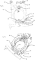
- FIGS. 3a and 3b show a blowing station 8 in an open position. It can be seen here the first Blasformitatiteil 6a and the second Blasformitatiteil 6b, which are pivotally provided with respect to a common pivot axis Y1 for opening and closing the blowing station.
- the reference numeral 72 designates a carrier for supporting the blow mold carrier parts 6a, 6b and the reference numerals 76 and 78 two levers, which are each preferably arranged rigidly on the blow mold carrier parts 6a and 6b.
- the pivotal movements of the blow mold carrier parts 6a and 6b can be effected via a drive mechanism (not shown). Inside the blow mold carrier parts 6a and 6b, a blow mold (not shown) is received.
- the reference numeral 82 refers to a first locking element, which is arranged on the second Blasformangoteil 6 b and the reference numeral 84 to a second locking element, which is here arranged on the first Blasformitatiteil 6 a.
- the second locking element is here rigidly arranged on the Blasformitatiteil 6a, while the first locking element 82 is pivotally mounted about a pivot axis Z.
- the blowing station 8 is here arranged with the mentioned carrier 72 on the main carrier 2 and moves in total along the arrow P1.
- the reference numeral 92 denotes a magnetic element, which here has an electromagnet 94. By activating this electromagnet 94, another magnet 96 or a magnetic element 96 can be attracted, this further magnetic element being fixedly connected to the first locking element 82. By this tightening of the further magnetic element 96, the locking element is pivoted about the pivot axis in the clockwise direction and can thus engage in the second locking element 84.
- Reference numeral 80 denotes the locking mechanism in its entirety.
- FIGS. 4a, 4b show a corresponding closed state of the blowing station, ie a state in which the first locking element 82 engages in the second locking element 84.
- the reference numeral 95 denotes a holding magnet, which cooperates with a magnetizable element 91, which is also fixedly arranged on the locking element 82, and thus holds the first locking element with a predetermined magnetic force in the locking position.
- This holding magnet 95 thus constitutes the above-mentioned second magnetic element.
- the individual magnetic forces can be designed such that the force of the magnet 95 can be overcome by the electromagnet 94.
- the device further includes another magnet 98 (the above-mentioned third magnetic element) which can hold the locking element 82 in an open position or attracts the magnet 91 when the locking element is opened so that the locking element 82 is held in the open position becomes.
- another magnet 98 the above-mentioned third magnetic element
- the magnet 95 and / or the magnet 98 are each designed as permanent magnets.
- all magnets which are arranged on the locking element are advantageously designed here as permanent magnets.
- the outer magnet 95 holds the first locking element 82 in the locking position after leaving the electromagnetic field.
- the pivot lever 85 To unlock the mold carrier (see. Fig. 3a, b ) after the blowing process in the concentricity, pushes a second, opposite polarized stationary electromagnet, on which the mold carrier passes, the pivot lever 85 from.
- the pivoting lever is, as mentioned, mounted on the first locking element 82 so that the hook 82a of the first locking element 82 pivots out of the contour 84a of the fixed second locking element.
- the magnet 98 holds after leaving the electromagnetic field, the first locking element in the unlocked position.
- the advantage of using an electromagnet is that it can be switched off for assembly and set-up work and also has no influence on tools.
- the advantage of a permanent magnet is that it does not cause any energy consumption.
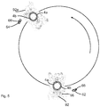
- Fig. 5 shows a further illustration to illustrate the invention.
- a carrier or a blow wheel 2 is shown, on which a plurality of blowing stations 8 (only two shown) are arranged.
- the first magnetic element 92 serves to open the locking element 82, as described above, and a second magnetic element 92a is used to reset the locking element or to open the lock, then the Blasstation 8 can be opened again.
- the reference numerals 4a, 4b refer to the blow moldings.
- the reference numeral 62 denotes a mechanically acting movement generating element which is disposed on the transport path P of the blowing stations after the electromagnet 94 and magnetic element 92, respectively.
- This mechanical-action movement-generating element Actuator 62 causes a pivoting movement of the locking member 82, if this is not yet locked at the position of the magnetic element 96.
- the movement generating element 62 may have an inclined surface 66, which cooperates with a projection (not shown) arranged under the magnet.
- this mechanically acting movement generating element 62 is arranged such that it does not contact the magnet 96 or the said projection when the locking element 82 is already locked in this position.
- the mechanically acting movement generating element 62 acts as an emergency locking element, if the magnetically acting locking should fail.
- the reference numeral 64 refers to another mechanically acting movement generating element, which is arranged correspondingly in the direction of movement of the blowing station 8 after the second magnetic element 92a and also serves to unlock the blowing station, if the second magnetic element has not yet reset the locking element at this position should.
- the other mechanically acting movement generating element contacted the magnet or the pivot lever 85 only when the magnetic unlocking should have failed.
- This second movement generating element may also have an inclined surface 64.
Landscapes
- Engineering & Computer Science (AREA)
- Manufacturing & Machinery (AREA)
- Mechanical Engineering (AREA)
- Blow-Moulding Or Thermoforming Of Plastics Or The Like (AREA)
- Moulds For Moulding Plastics Or The Like (AREA)
Claims (9)
- Dispositif (1) de transformation d'ébauches en matière plastique (10) en récipients en matière plastique (10a), comprenant au moins une station de soufflage (8) agencée sur un support (2) mobile, dans lequel cette station de soufflage (8) comprend un support de moule de soufflage destiné à retenir un moule de soufflage (4a, 4b) et ce support de moule de soufflage comprend une première partie de support de moule de soufflage (6a) et une deuxième partie de moule de soufflage (6b), laquelle peut pivoter vis-à-vis de la première partie de moule de soufflage (6a) par rapport à un premier axe de pivotement (Y1) prédéfini, afin d'ouvrir et de fermer le moule de soufflage (4a, 4b) et dans lequel la station de soufflage (8) comprend en outre un mécanisme de verrouillage (80), afin de verrouiller la première partie de support de moule de soufflage (6a) vis-à-vis de la deuxième partie de support de moule de soufflage (6b) et le mécanisme de verrouillage (80) comprend un premier élément de verrouillage (82) agencé au moins indirectement sur la première partie de support de moule de soufflage (6a) et un deuxième élément de verrouillage (84) agencé au moins indirectement sur la deuxième partie de support de moule de soufflage (6b), dans lequel les éléments de verrouillage (82, 84) coopèrent lorsque les parties de support de moule de soufflage (6a, 6b) se trouvent dans un état verrouillé,
dans lequel le dispositif (1) comprend un premier élément magnétique (92) au moins par intermittence, par rapport auquel le premier élément de verrouillage (82) est mobile et lequel provoque, à la suite d'une interaction magnétique sans contact, un déplacement du premier élément de verrouillage (82) pour le verrouillage des parties de support de moule de soufflage (6a, 6b), afin qu'une solution sans contact et donc sans entretien et sans friction soit créée à l'aide dudit au moins un élément magnétique (92) au moins par intermittence, afin de provoquer le verrouillage du moule de soufflage (4a, 4b), et dans lequel le premier élément de verrouillage (82) peut pivoter par rapport à un deuxième axe de pivotement (Z) prédéfini, et dans lequel ce deuxième axe de pivotement (Z), par rapport auquel le premier élément de verrouillage (82) peut pivoter, s'étend sensiblement parallèlement à l'axe de pivotement (Y1) autour duquel la partie de support de moule de soufflage (6a, 6b) peut pivoter. - Dispositif selon la revendication 1,
caractérisé en ce que
l'élément magnétique (92) est monté fixe par rapport à la station de soufflage (8). - Dispositif (1) selon au moins l'une des revendications précédentes,
caractérisé en ce que
l'élément magnétique (92) comprend un électroaimant (94). - Dispositif (1) selon au moins l'une des revendications précédentes,
caractérisé en ce que
un deuxième élément magnétique (95), lequel retient l'élément de verrouillage (82) par intermittence dans une position de verrouillage, est prévu sur la station de soufflage (8). - Dispositif (1) selon la revendication 4,
caractérisé en ce que
un troisième élément magnétique (98), lequel maintient par intermittence le premier élément de verrouillage (82) dans une position non verrouillée, est prévu sur la station de soufflage (8). - Dispositif (1) selon au moins l'une des revendications précédentes,
caractérisé en ce que
le dispositif (1) comprend un élément de génération de déplacement (62) monté fixe, lequel déplace l'élément de verrouillage (82). - Dispositif (1) selon au moins l'une des revendications précédentes,
caractérisé en ce que
le dispositif (1) comprend un quatrième élément magnétique (92a) au moins par intermittence, par rapport auquel le premier élément de verrouillage (82) est mobile et lequel, à la suite d'une interaction magnétique, provoque un déplacement du premier élément de verrouillage (82) pour le déverrouillage des parties de support de moule de soufflage (6a, 6b). - Dispositif (1) selon au moins l'une des revendications 4 à 7,
caractérisé en ce que
le premier élément magnétique (92) et le deuxième élément magnétique (92a) sont agencés en des emplacements différents le long du trajet de déplacement de la station de soufflage (8). - Procédé de transformation d'ébauches en matière plastique (10) en récipients en matière plastique (10a), dans lequel l'ébauche en matière plastique (10) est transformée en récipient en matière plastique (10a) dans une station de soufflage (8) agencée sur un support (2) mobile et dans lequel la station de soufflage (8) comprend une première partie de support de moule de soufflage (6a) pouvant pivoter par rapport à un premier axe de pivotement (Y1) et une deuxième partie de support de moule de soufflage (6b) et la première partie de support de moule de soufflage (6a) et la deuxième partie de support de moule de soufflage (6b) sont verrouillées l'une par rapport à l'autre au moyen d'un mécanisme de verrouillage (80) et dans lequel un premier élément de verrouillage (82) effectue un déplacement par rapport à un deuxième axe (X) pour le verrouillage des parties de support de moule de soufflage (6a, 6b),
dans lequel le premier élément de verrouillage (82) est poussé par une force magnétique dans une position de verrouillage, dans lequel la force magnétique est générée par un élément magnétique (92) vis-à-vis duquel le premier élément de verrouillage (82) est monté mobile, afin de créer ainsi une solution sans contact et donc sans entretien et sans friction à l'aide dudit au moins un élément magnétique (92) au moins par intermittence, afin de provoquer le verrouillage du moule de soufflage (4a, 4b), et dans lequel le premier élément de verrouillage (82) est amené à pivoter vis-à-vis d'un deuxième axe de pivotement (Z) prédéfini, et dans lequel ce deuxième axe de pivotement (Z), par rapport auquel le premier élément de verrouillage (82) est amené à pivoter, s'étend sensiblement parallèlement à l'axe de pivotement (Y1) autour duquel la partie de support de moule de soufflage (6a, 6b) peut pivoter.
Applications Claiming Priority (1)
| Application Number | Priority Date | Filing Date | Title |
|---|---|---|---|
| DE102011101262A DE102011101262A1 (de) | 2011-05-11 | 2011-05-11 | Vorrichtung zum Umformen von Kunststoffvorformlingen zu Kunststoffbehältnissen mit magnetisch betätigter Verriegelung |
Publications (3)
| Publication Number | Publication Date |
|---|---|
| EP2522484A2 EP2522484A2 (fr) | 2012-11-14 |
| EP2522484A3 EP2522484A3 (fr) | 2014-11-05 |
| EP2522484B1 true EP2522484B1 (fr) | 2018-05-02 |
Family
ID=46177301
Family Applications (1)
| Application Number | Title | Priority Date | Filing Date |
|---|---|---|---|
| EP12167262.0A Not-in-force EP2522484B1 (fr) | 2011-05-11 | 2012-05-09 | Dispositif et procédé de déformation d'ébauches en plastique en conteneurs en plastique dotés d'un verrouillage à actionnement magnétique |
Country Status (4)
| Country | Link |
|---|---|
| US (1) | US9067354B2 (fr) |
| EP (1) | EP2522484B1 (fr) |
| CN (1) | CN102774000B (fr) |
| DE (1) | DE102011101262A1 (fr) |
Families Citing this family (9)
| Publication number | Priority date | Publication date | Assignee | Title |
|---|---|---|---|---|
| FR2949709B1 (fr) * | 2009-09-08 | 2011-10-07 | Sidel Participations | Machine pour la fabrication de recipients comportant un module de commande de dispositifs d'une unite de moulage en vue d'operer un changement de moule |
| DE102012106821A1 (de) * | 2012-07-26 | 2014-05-22 | Krones Ag | Vorrichtung zum Umformen von Kunststoffvorformlingen mit direkt angesteuerter Verriegelung |
| DE102012023703A1 (de) | 2012-12-05 | 2014-06-05 | Krones Ag | Blasformmaschine |
| DE102013102878A1 (de) * | 2013-03-21 | 2014-09-25 | Krones Ag | Vorrichtung zum Transportieren von Kunststoffvorformlingen mit kontinuierlicher Zuführung |
| CN103552231B (zh) * | 2013-10-30 | 2016-02-03 | 广州达意隆包装机械股份有限公司 | 一种吹瓶机锁模机构 |
| FR3027548B1 (fr) * | 2014-10-24 | 2016-12-09 | Sidel Participations | Mecanisme de commande d'ouverture de moule a axe double |
| DE102017112496A1 (de) * | 2017-06-07 | 2018-12-13 | Krones Ag | Blasformanordnung zum Umformen von Kunststoffvorformlingen zu Kunststoffbehältnissen mit Kraftableitungselementen und Verfahren hierzu sowie Vorrichtung zum Umformen von Kunststoffvorformlingen mit Verriegelungseinrichtung |
| FR3101010B1 (fr) * | 2019-09-19 | 2021-09-10 | Sidel Participations | Unité de moulage à verrouillage par crochets |
| CN117382146A (zh) * | 2023-10-17 | 2024-01-12 | 江苏新美星包装机械股份有限公司 | 吹瓶机制瓶模架中锁模轴的定位方法及定位机构 |
Family Cites Families (10)
| Publication number | Priority date | Publication date | Assignee | Title |
|---|---|---|---|---|
| DE19918709A1 (de) * | 1999-04-26 | 2000-11-02 | Apis Maschinenbau Gmbh | Werkzeugmodul für eine Spritzblasmaschine und Verfahren zum Betreiben dieser Maschine |
| DE29913182U1 (de) * | 1999-07-28 | 2000-08-31 | KRONES AG, 93073 Neutraubling | Blasform |
| RU2184654C1 (ru) * | 2001-03-20 | 2002-07-10 | Общество с ограниченной ответственностью "МГП Этакор" | Способ удержания пресс-формы от размыкания при формировании изделий |
| FR2914580B1 (fr) * | 2007-04-06 | 2013-04-12 | Sidel Participations | Dispositif de soufflage ou d'etirage soufflage pour la fabrication de recipients comprenant des moyens a pince propres a supporter une ebauche par son col |
| EP2130663B8 (fr) * | 2008-06-05 | 2013-09-25 | PARCO S.r.l. | Machine de thermoformage comprenant un cadre de capot réglable |
| EP2263854B1 (fr) | 2008-12-19 | 2013-05-01 | Krones AG | Machine de formage par soufflage entraînée de manière électrique et le procédé |
| DE102009007717A1 (de) * | 2009-02-05 | 2010-08-12 | Krones Ag | Verschleißreduktion von Steuerkurven |
| DE102009039696A1 (de) * | 2009-09-02 | 2011-03-24 | Krones Ag | Vorrichtung zum Umformen von Kunststoffbehältnissen mit einer Blasform |
| DE102009039699A1 (de) * | 2009-09-02 | 2011-04-28 | Krones Ag | Verfahren und Vorrichtung zur Montage und/oder Demontage von Blasformen |
| CN101890805B (zh) * | 2010-04-13 | 2012-07-11 | 苏州同大机械有限公司 | 中空塑料制品成型机的磁力合模装置 |
-
2011
- 2011-05-11 DE DE102011101262A patent/DE102011101262A1/de not_active Ceased
-
2012
- 2012-05-09 EP EP12167262.0A patent/EP2522484B1/fr not_active Not-in-force
- 2012-05-10 US US13/468,290 patent/US9067354B2/en not_active Expired - Fee Related
- 2012-05-11 CN CN201210147900.XA patent/CN102774000B/zh not_active Expired - Fee Related
Non-Patent Citations (1)
| Title |
|---|
| None * |
Also Published As
| Publication number | Publication date |
|---|---|
| US9067354B2 (en) | 2015-06-30 |
| CN102774000B (zh) | 2015-05-20 |
| DE102011101262A1 (de) | 2012-11-15 |
| US20120286455A1 (en) | 2012-11-15 |
| CN102774000A (zh) | 2012-11-14 |
| EP2522484A2 (fr) | 2012-11-14 |
| EP2522484A3 (fr) | 2014-11-05 |
Similar Documents
| Publication | Publication Date | Title |
|---|---|---|
| EP2522484B1 (fr) | Dispositif et procédé de déformation d'ébauches en plastique en conteneurs en plastique dotés d'un verrouillage à actionnement magnétique | |
| EP2511070B1 (fr) | Dispositif et procédé de transformation de préformes en matière synthétique en récipients en plastique avec mouvements couplés de verrouillage et d'oscillation | |
| EP2495086B1 (fr) | Souffleuse dotée d'un verrouillage de moule de soufflage dans la salle stérile | |
| EP1979153B1 (fr) | Dispositif de moulage par soufflage de recipients dote d'elements de transport de type pince a deux bras | |
| DE69918692T2 (de) | Verbesserte vorrichtung zum herstellen von behältern aus kunststoffmaterial | |
| DE102007022638A1 (de) | Vorrichtung zur Blasformung von Behältern | |
| EP2848384B1 (fr) | Dispositif de transformation de préformes en matière synthétique avec salle blanche | |
| EP2740582B1 (fr) | Machine de formage par soufflage et procédé apparenté. | |
| EP3294525B1 (fr) | Poste de moulage pour les machines de moulage par soufflage sans coussins de pression | |
| EP2570251B1 (fr) | Souffleuse avec stations de soufflage démontables | |
| DE10354506A1 (de) | Vorrichtung zur Blasformung von Behältern | |
| EP2559545A1 (fr) | Dispositif et procédé moulage par soufflage d'ébauches en plastique en conteneurs en plastique doté d'un coussin de pression | |
| DE102011116192A1 (de) | Verfahren und Vorrichtung zur Blasformung von Behältern | |
| EP2495090A1 (fr) | Souffleuse dotée d'une chambre stérile et d'une entrée de fluides dans la chambre stérile | |
| EP2848386B1 (fr) | Appareil pour souffler des préformes en matière plastique en conteneurs en matière plastique | |
| EP2368692A2 (fr) | Dispositif de moulage par soufflage doté d'un mécanisme de verrouillage contrôlé | |
| EP2913174B1 (fr) | Machine de formage par soufflage à centrage du fond de moule de soufflage | |
| DE202013104120U1 (de) | Vorrichtung zum Umformen von Kunststoffvorformlingen zu Kunststoffbehältnissen mit asymmetrischer Blasformöffnungsbewegung | |
| DE102012104754A1 (de) | Blasformmaschine mit umlaufender Verriegelungskurve | |
| DE102018131396A1 (de) | Aseptische Blasformmaschine mit Entlüftungskanal | |
| DE202013008081U1 (de) | Vorrichtung zum Umformen von Kunststoffvorformlingen zu Kunststoffbehältnissen sowie Blasformträger | |
| WO2018224479A1 (fr) | Ensemble moule de soufflage servant à transformer des préformes en matière plastique en contenants en matière plastique comportant des éléments de déviation de force et un procédé dédié à cet effet et un dispositif servant à transformer des préformes en matière plastique comportant un dispositif de verrouillage | |
| EP4299280B1 (fr) | Dispositif et procédé de déformation d'ébauches en plastique en récipients en plastique | |
| DE102013102692A1 (de) | Verfahren und Vorrichtung zum Umformen von Kunststoffvorformlingen zu Kunststoffbehältnissen sowie Getränkebehälterherstellanlage und/oder Getränkeabfüllanlage | |
| DE102012106821A1 (de) | Vorrichtung zum Umformen von Kunststoffvorformlingen mit direkt angesteuerter Verriegelung |
Legal Events
| Date | Code | Title | Description |
|---|---|---|---|
| PUAI | Public reference made under article 153(3) epc to a published international application that has entered the european phase |
Free format text: ORIGINAL CODE: 0009012 |
|
| AK | Designated contracting states |
Kind code of ref document: A2 Designated state(s): AL AT BE BG CH CY CZ DE DK EE ES FI FR GB GR HR HU IE IS IT LI LT LU LV MC MK MT NL NO PL PT RO RS SE SI SK SM TR |
|
| AX | Request for extension of the european patent |
Extension state: BA ME |
|
| PUAL | Search report despatched |
Free format text: ORIGINAL CODE: 0009013 |
|
| AK | Designated contracting states |
Kind code of ref document: A3 Designated state(s): AL AT BE BG CH CY CZ DE DK EE ES FI FR GB GR HR HU IE IS IT LI LT LU LV MC MK MT NL NO PL PT RO RS SE SI SK SM TR |
|
| AX | Request for extension of the european patent |
Extension state: BA ME |
|
| RIC1 | Information provided on ipc code assigned before grant |
Ipc: B29C 49/56 20060101AFI20140930BHEP |
|
| 17P | Request for examination filed |
Effective date: 20150505 |
|
| RBV | Designated contracting states (corrected) |
Designated state(s): AL AT BE BG CH CY CZ DE DK EE ES FI FR GB GR HR HU IE IS IT LI LT LU LV MC MK MT NL NO PL PT RO RS SE SI SK SM TR |
|
| 17Q | First examination report despatched |
Effective date: 20170628 |
|
| GRAP | Despatch of communication of intention to grant a patent |
Free format text: ORIGINAL CODE: EPIDOSNIGR1 |
|
| RIC1 | Information provided on ipc code assigned before grant |
Ipc: B29C 49/48 20060101ALN20171204BHEP Ipc: B29C 49/56 20060101AFI20171204BHEP Ipc: B29C 49/36 20060101ALN20171204BHEP Ipc: B29C 49/06 20060101ALN20171204BHEP |
|
| INTG | Intention to grant announced |
Effective date: 20171218 |
|
| GRAS | Grant fee paid |
Free format text: ORIGINAL CODE: EPIDOSNIGR3 |
|
| GRAA | (expected) grant |
Free format text: ORIGINAL CODE: 0009210 |
|
| REG | Reference to a national code |
Ref country code: FR Ref legal event code: PLFP Year of fee payment: 7 |
|
| AK | Designated contracting states |
Kind code of ref document: B1 Designated state(s): AL AT BE BG CH CY CZ DE DK EE ES FI FR GB GR HR HU IE IS IT LI LT LU LV MC MK MT NL NO PL PT RO RS SE SI SK SM TR |
|
| REG | Reference to a national code |
Ref country code: GB Ref legal event code: FG4D Free format text: NOT ENGLISH |
|
| RIN1 | Information on inventor provided before grant (corrected) |
Inventor name: WEISS, JOHANNES |
|
| REG | Reference to a national code |
Ref country code: CH Ref legal event code: EP Ref country code: AT Ref legal event code: REF Ref document number: 994729 Country of ref document: AT Kind code of ref document: T Effective date: 20180515 |
|
| REG | Reference to a national code |
Ref country code: DE Ref legal event code: R096 Ref document number: 502012012619 Country of ref document: DE |
|
| REG | Reference to a national code |
Ref country code: IE Ref legal event code: FG4D Free format text: LANGUAGE OF EP DOCUMENT: GERMAN |
|
| REG | Reference to a national code |
Ref country code: NL Ref legal event code: MP Effective date: 20180502 |
|
| REG | Reference to a national code |
Ref country code: LT Ref legal event code: MG4D |
|
| PG25 | Lapsed in a contracting state [announced via postgrant information from national office to epo] |
Ref country code: ES Free format text: LAPSE BECAUSE OF FAILURE TO SUBMIT A TRANSLATION OF THE DESCRIPTION OR TO PAY THE FEE WITHIN THE PRESCRIBED TIME-LIMIT Effective date: 20180502 Ref country code: SE Free format text: LAPSE BECAUSE OF FAILURE TO SUBMIT A TRANSLATION OF THE DESCRIPTION OR TO PAY THE FEE WITHIN THE PRESCRIBED TIME-LIMIT Effective date: 20180502 Ref country code: BG Free format text: LAPSE BECAUSE OF FAILURE TO SUBMIT A TRANSLATION OF THE DESCRIPTION OR TO PAY THE FEE WITHIN THE PRESCRIBED TIME-LIMIT Effective date: 20180802 Ref country code: FI Free format text: LAPSE BECAUSE OF FAILURE TO SUBMIT A TRANSLATION OF THE DESCRIPTION OR TO PAY THE FEE WITHIN THE PRESCRIBED TIME-LIMIT Effective date: 20180502 Ref country code: NO Free format text: LAPSE BECAUSE OF FAILURE TO SUBMIT A TRANSLATION OF THE DESCRIPTION OR TO PAY THE FEE WITHIN THE PRESCRIBED TIME-LIMIT Effective date: 20180802 Ref country code: LT Free format text: LAPSE BECAUSE OF FAILURE TO SUBMIT A TRANSLATION OF THE DESCRIPTION OR TO PAY THE FEE WITHIN THE PRESCRIBED TIME-LIMIT Effective date: 20180502 |
|
| PG25 | Lapsed in a contracting state [announced via postgrant information from national office to epo] |
Ref country code: GR Free format text: LAPSE BECAUSE OF FAILURE TO SUBMIT A TRANSLATION OF THE DESCRIPTION OR TO PAY THE FEE WITHIN THE PRESCRIBED TIME-LIMIT Effective date: 20180803 Ref country code: HR Free format text: LAPSE BECAUSE OF FAILURE TO SUBMIT A TRANSLATION OF THE DESCRIPTION OR TO PAY THE FEE WITHIN THE PRESCRIBED TIME-LIMIT Effective date: 20180502 Ref country code: NL Free format text: LAPSE BECAUSE OF FAILURE TO SUBMIT A TRANSLATION OF THE DESCRIPTION OR TO PAY THE FEE WITHIN THE PRESCRIBED TIME-LIMIT Effective date: 20180502 Ref country code: LV Free format text: LAPSE BECAUSE OF FAILURE TO SUBMIT A TRANSLATION OF THE DESCRIPTION OR TO PAY THE FEE WITHIN THE PRESCRIBED TIME-LIMIT Effective date: 20180502 Ref country code: RS Free format text: LAPSE BECAUSE OF FAILURE TO SUBMIT A TRANSLATION OF THE DESCRIPTION OR TO PAY THE FEE WITHIN THE PRESCRIBED TIME-LIMIT Effective date: 20180502 |
|
| REG | Reference to a national code |
Ref country code: CH Ref legal event code: PL |
|
| PG25 | Lapsed in a contracting state [announced via postgrant information from national office to epo] |
Ref country code: PT Free format text: LAPSE BECAUSE OF FAILURE TO SUBMIT A TRANSLATION OF THE DESCRIPTION OR TO PAY THE FEE WITHIN THE PRESCRIBED TIME-LIMIT Effective date: 20180903 |
|
| REG | Reference to a national code |
Ref country code: BE Ref legal event code: MM Effective date: 20180531 |
|
| PG25 | Lapsed in a contracting state [announced via postgrant information from national office to epo] |
Ref country code: CZ Free format text: LAPSE BECAUSE OF FAILURE TO SUBMIT A TRANSLATION OF THE DESCRIPTION OR TO PAY THE FEE WITHIN THE PRESCRIBED TIME-LIMIT Effective date: 20180502 Ref country code: RO Free format text: LAPSE BECAUSE OF FAILURE TO SUBMIT A TRANSLATION OF THE DESCRIPTION OR TO PAY THE FEE WITHIN THE PRESCRIBED TIME-LIMIT Effective date: 20180502 Ref country code: PL Free format text: LAPSE BECAUSE OF FAILURE TO SUBMIT A TRANSLATION OF THE DESCRIPTION OR TO PAY THE FEE WITHIN THE PRESCRIBED TIME-LIMIT Effective date: 20180502 Ref country code: EE Free format text: LAPSE BECAUSE OF FAILURE TO SUBMIT A TRANSLATION OF THE DESCRIPTION OR TO PAY THE FEE WITHIN THE PRESCRIBED TIME-LIMIT Effective date: 20180502 Ref country code: DK Free format text: LAPSE BECAUSE OF FAILURE TO SUBMIT A TRANSLATION OF THE DESCRIPTION OR TO PAY THE FEE WITHIN THE PRESCRIBED TIME-LIMIT Effective date: 20180502 Ref country code: SK Free format text: LAPSE BECAUSE OF FAILURE TO SUBMIT A TRANSLATION OF THE DESCRIPTION OR TO PAY THE FEE WITHIN THE PRESCRIBED TIME-LIMIT Effective date: 20180502 |
|
| REG | Reference to a national code |
Ref country code: DE Ref legal event code: R097 Ref document number: 502012012619 Country of ref document: DE |
|
| REG | Reference to a national code |
Ref country code: IE Ref legal event code: MM4A |
|
| PG25 | Lapsed in a contracting state [announced via postgrant information from national office to epo] |
Ref country code: SM Free format text: LAPSE BECAUSE OF FAILURE TO SUBMIT A TRANSLATION OF THE DESCRIPTION OR TO PAY THE FEE WITHIN THE PRESCRIBED TIME-LIMIT Effective date: 20180502 Ref country code: CH Free format text: LAPSE BECAUSE OF NON-PAYMENT OF DUE FEES Effective date: 20180531 Ref country code: LI Free format text: LAPSE BECAUSE OF NON-PAYMENT OF DUE FEES Effective date: 20180531 |
|
| PLBE | No opposition filed within time limit |
Free format text: ORIGINAL CODE: 0009261 |
|
| STAA | Information on the status of an ep patent application or granted ep patent |
Free format text: STATUS: NO OPPOSITION FILED WITHIN TIME LIMIT |
|
| PG25 | Lapsed in a contracting state [announced via postgrant information from national office to epo] |
Ref country code: MC Free format text: LAPSE BECAUSE OF FAILURE TO SUBMIT A TRANSLATION OF THE DESCRIPTION OR TO PAY THE FEE WITHIN THE PRESCRIBED TIME-LIMIT Effective date: 20180502 Ref country code: LU Free format text: LAPSE BECAUSE OF NON-PAYMENT OF DUE FEES Effective date: 20180509 |
|
| 26N | No opposition filed |
Effective date: 20190205 |
|
| GBPC | Gb: european patent ceased through non-payment of renewal fee |
Effective date: 20180802 |
|
| PG25 | Lapsed in a contracting state [announced via postgrant information from national office to epo] |
Ref country code: IE Free format text: LAPSE BECAUSE OF NON-PAYMENT OF DUE FEES Effective date: 20180509 |
|
| PG25 | Lapsed in a contracting state [announced via postgrant information from national office to epo] |
Ref country code: BE Free format text: LAPSE BECAUSE OF NON-PAYMENT OF DUE FEES Effective date: 20180531 Ref country code: SI Free format text: LAPSE BECAUSE OF FAILURE TO SUBMIT A TRANSLATION OF THE DESCRIPTION OR TO PAY THE FEE WITHIN THE PRESCRIBED TIME-LIMIT Effective date: 20180502 |
|
| REG | Reference to a national code |
Ref country code: AT Ref legal event code: MM01 Ref document number: 994729 Country of ref document: AT Kind code of ref document: T Effective date: 20180509 |
|
| PG25 | Lapsed in a contracting state [announced via postgrant information from national office to epo] |
Ref country code: GB Free format text: LAPSE BECAUSE OF NON-PAYMENT OF DUE FEES Effective date: 20180802 Ref country code: AT Free format text: LAPSE BECAUSE OF NON-PAYMENT OF DUE FEES Effective date: 20180509 |
|
| PG25 | Lapsed in a contracting state [announced via postgrant information from national office to epo] |
Ref country code: AL Free format text: LAPSE BECAUSE OF FAILURE TO SUBMIT A TRANSLATION OF THE DESCRIPTION OR TO PAY THE FEE WITHIN THE PRESCRIBED TIME-LIMIT Effective date: 20180502 |
|
| PG25 | Lapsed in a contracting state [announced via postgrant information from national office to epo] |
Ref country code: MT Free format text: LAPSE BECAUSE OF FAILURE TO SUBMIT A TRANSLATION OF THE DESCRIPTION OR TO PAY THE FEE WITHIN THE PRESCRIBED TIME-LIMIT Effective date: 20180502 |
|
| PG25 | Lapsed in a contracting state [announced via postgrant information from national office to epo] |
Ref country code: TR Free format text: LAPSE BECAUSE OF FAILURE TO SUBMIT A TRANSLATION OF THE DESCRIPTION OR TO PAY THE FEE WITHIN THE PRESCRIBED TIME-LIMIT Effective date: 20180502 |
|
| PG25 | Lapsed in a contracting state [announced via postgrant information from national office to epo] |
Ref country code: HU Free format text: LAPSE BECAUSE OF FAILURE TO SUBMIT A TRANSLATION OF THE DESCRIPTION OR TO PAY THE FEE WITHIN THE PRESCRIBED TIME-LIMIT; INVALID AB INITIO Effective date: 20120509 |
|
| PG25 | Lapsed in a contracting state [announced via postgrant information from national office to epo] |
Ref country code: CY Free format text: LAPSE BECAUSE OF FAILURE TO SUBMIT A TRANSLATION OF THE DESCRIPTION OR TO PAY THE FEE WITHIN THE PRESCRIBED TIME-LIMIT Effective date: 20180502 Ref country code: MK Free format text: LAPSE BECAUSE OF NON-PAYMENT OF DUE FEES Effective date: 20180502 |
|
| PG25 | Lapsed in a contracting state [announced via postgrant information from national office to epo] |
Ref country code: IS Free format text: LAPSE BECAUSE OF FAILURE TO SUBMIT A TRANSLATION OF THE DESCRIPTION OR TO PAY THE FEE WITHIN THE PRESCRIBED TIME-LIMIT Effective date: 20180902 |
|
| PGFP | Annual fee paid to national office [announced via postgrant information from national office to epo] |
Ref country code: FR Payment date: 20210412 Year of fee payment: 10 Ref country code: DE Payment date: 20210413 Year of fee payment: 10 Ref country code: IT Payment date: 20210412 Year of fee payment: 10 |
|
| REG | Reference to a national code |
Ref country code: DE Ref legal event code: R119 Ref document number: 502012012619 Country of ref document: DE |
|
| PG25 | Lapsed in a contracting state [announced via postgrant information from national office to epo] |
Ref country code: FR Free format text: LAPSE BECAUSE OF NON-PAYMENT OF DUE FEES Effective date: 20220531 |
|
| PG25 | Lapsed in a contracting state [announced via postgrant information from national office to epo] |
Ref country code: DE Free format text: LAPSE BECAUSE OF NON-PAYMENT OF DUE FEES Effective date: 20221201 |
|
| PG25 | Lapsed in a contracting state [announced via postgrant information from national office to epo] |
Ref country code: IT Free format text: LAPSE BECAUSE OF NON-PAYMENT OF DUE FEES Effective date: 20220509 |