EP2522771A2 - Wäschetrockner - Google Patents
Wäschetrockner Download PDFInfo
- Publication number
- EP2522771A2 EP2522771A2 EP12171057A EP12171057A EP2522771A2 EP 2522771 A2 EP2522771 A2 EP 2522771A2 EP 12171057 A EP12171057 A EP 12171057A EP 12171057 A EP12171057 A EP 12171057A EP 2522771 A2 EP2522771 A2 EP 2522771A2
- Authority
- EP
- European Patent Office
- Prior art keywords
- tank
- drier
- door
- bracket
- protrusion
- Prior art date
- Legal status (The legal status is an assumption and is not a legal conclusion. Google has not performed a legal analysis and makes no representation as to the accuracy of the status listed.)
- Withdrawn
Links
Images



Classifications
-
- D—TEXTILES; PAPER
- D06—TREATMENT OF TEXTILES OR THE LIKE; LAUNDERING; FLEXIBLE MATERIALS NOT OTHERWISE PROVIDED FOR
- D06F—LAUNDERING, DRYING, IRONING, PRESSING OR FOLDING TEXTILE ARTICLES
- D06F58/00—Domestic laundry dryers
- D06F58/20—General details of domestic laundry dryers
- D06F58/24—Condensing arrangements
Definitions
- the present invention relates to a laundry drier.
- the present invention relates to a laundry drier of the type comprising a casing; a laundry loading-unloading opening; a door closing said opening; a condensation collecting device for condensed water extracted from the laundry; a removable tank; a liquid circulation device connecting the condensation collecting device to the removable tank to convey the condensed water from the condensation collecting device to the removable tank; and an overflow line fluidly connecting the removable tank to the condensation collecting device.
- the overflow line normally forms part of the removable tank itself, and is defined by a groove formed on the outside of the removable tank to conduct overflow water from the removable tank into the condensation collecting device.
- this solution has the major drawback of condensed water flowing uncontrolled and unconfined within the drier, and dripping on the outside of the removable tank, if the removable tank is extracted after water is fed along the overflow from the removable tank into the condensation collecting device.
- driers of the type described above such as, for example, the drier disclosed in EP-0789105
- the mounting of the removable tank requires the provision of a casing adapted to receive the tank in a removable manner and is not only very complicated and bulky from the structural point of view, but also in no way "user friendly” and ergonomic.
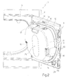
- Number 1 in Figure 1 indicates as a whole a laundry drier comprising a parallelepiped-shaped casing 2 designed to rest on the floor and housing a known laundry drying drum (not shown); a laundry loading-unloading opening 3; and a door 4 hinged to a front wall of casing 2 to rotate to and from a closed position closing opening 3 and the drying drum (not shown).
- Drier 1 also comprises a known hot-air-generating device 5 for circulating hot air inside the drum (not shown) to dry the laundry; and a condensation collecting device comprising a tank 6 located at the bottom of casing 2 to collect the condensed water extracted from the laundry by the hot air flowing through it.
- a known hot-air-generating device 5 for circulating hot air inside the drum (not shown) to dry the laundry
- a condensation collecting device comprising a tank 6 located at the bottom of casing 2 to collect the condensed water extracted from the laundry by the hot air flowing through it.
- the drier also comprises a liquid circulation device which, in the embodiment shown, comprises, in turn, a pump 7 for drawing the condensed water from tank 6 and feeding it along a feed line 8 into a reservoir 9, which forms part of drier 1 and comprises a tank fitted removably to, and projecting from, an inner wall 10 of door 4 facing opening 3.
- a liquid circulation device which, in the embodiment shown, comprises, in turn, a pump 7 for drawing the condensed water from tank 6 and feeding it along a feed line 8 into a reservoir 9, which forms part of drier 1 and comprises a tank fitted removably to, and projecting from, an inner wall 10 of door 4 facing opening 3.
- reservoir 9 is substantially truncated-cone-shaped, is fitted with its wide side 11 facing wall 10, and has a hole 12 at the top which, when door 4 is closed and reservoir 9 projects inside the drying drum (not shown), is aligned with an outlet 13 of feed line 8, so that the water drawn from tank 6 by pump 7 flows into reservoir 9 by force of gravity.
- Hole 12 also acts as a pour opening by which to pour the condensed water out of reservoir 9 when this is detached from door 4.
- Reservoir 9 is fitted to door 4 by two brackets 14 integral with wall 10 and each engaging a respective recess 15 formed on a corresponding side of reservoir 9, and is locked in position on wall 10 by two catches 16, which are fitted to reservoir 9, engage respective slots 18 formed in wall 10, and are released manually by the user acting on a lever (not shown) built into a handgrip 17 for easy handling of reservoir 9 by the user.
- an elongated protrusion 15a is provided which protrudes transversely from the respective side of reservoir 9 and, when reservoir 9 is mounted on door 4, slidably engages a respective guide 14a provided on the inner surface of the respective bracket 14 in a position facing the other guide 14a.
- each guide 14a has a funnel-shaped upper inlet portion and an enlarged lower portion.
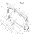
- protrusions 15a engage, with a transverse play, the enlarged lower portions of the respective guides 14a so as to hook reservoir 9 to door 4, but to allow reservoir 9, still resting on brackets 14, to tilt through a predetermined angle of about 10-15° in relation to door 4 ( Figure 2 ) about a substantially horizontal axis extending transversely to the mounting direction and parallel to wall 10 for insertion of catches 16 into slots 18.
- protrusions 15a when engaged in the respective lower portions of guides 14a, define, with said lower portions, a virtual hinge allowing reservoir 9 to assume spontaneously and automatically, when lowered, a backwards inclined position.
- the upper surface of each bracket 14 and the upper surface of each recess 15 are equally curved in order to allow reservoir 9 to tilt freely about the axis of the aforementioned virtual hinge without loosing contact with brackets 14 so as to be always supported thereby.
- drier 1 also comprises an overflow line 19 connecting reservoir 9 to tank 6 to feed overflow water from reservoir 9 back into tank 6.
- overflow line 19 comprises a portion 26, which may be mounted on door 4, but which, in the embodiment shown, is built within door 4.
- Portion 26 consists of a L-shaped pipe of substantially rectangular cross section and is fitted to wall 10 between wall 10 itself and an outer panel 20 of door 4.
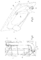
- overflow passage 26 has an inlet 21 aligned with a hole in wall 10 and communicating, when reservoir 9 is fitted to door 4, with the inside of reservoir 9 via a valve 22, which is inserted through an opening in side 11 of reservoir 9, close to hole 12, and is movable between an open position, when reservoir 9 is fitted to door 4 ( Figure 1 ), and a closed position when reservoir 9 is detached from door 4 ( Figure 3 ).
- Insertion of valve 22 into inlet 21 is carried out during the mounting of reservoir 9 onto door 4 simultaneously with the insertion of catches 16 into slots 18 described above.
- Valve 22 prevents water leaking from side 11 of reservoir 9, when the water level in reservoir 9 reaches the level of valve 22 and reservoir 9 is detached from door 4 to be emptied.
- portion 26 has an outlet 23 aligned with an opening through wall 10 and closed by a valve 24, which is movable between a closed position ( Figures 2 , 3 , 5 ) when door 4 is open, and an open position (not shown) when door 4 is closed. In the open position, valve 24 connects outlet 23 of portion 26 to a pipe (shown in figure 6 ) of overflow line 19 communicating directly with tank 6.
- Valve 24 automatically closes the outlet of portion 26, when door 4 is opened, to prevent water leakage in the event the water level inside reservoir 9 has reached the level of valve 22 and overflow line 19 is full.
- reservoir 9 On the wall facing opening 3 and on the opposite side to side 11, reservoir 9 has a window 25 of transparent material to enable the user to check the water level inside reservoir 9 and empty it in time.
- drier 1 comprises a float (not shown) located inside tank 6 and connected to pump 7 to activate it when the water level inside tank 6 exceeds a given level. If reservoir 9 is full, any water pumped by pump 7 to reservoir 9 flows back into tank 6 along overflow line 19. In which case, as opposed to being reduced by pump 7, the water level inside tank 6 is increased by the continual inflow of water extracted from the laundry; and the increase in the water level is detected by the float, which stops drier 1.
Landscapes
- Engineering & Computer Science (AREA)
- Textile Engineering (AREA)
- Detail Structures Of Washing Machines And Dryers (AREA)
- Drying Of Solid Materials (AREA)
Priority Applications (1)
| Application Number | Priority Date | Filing Date | Title |
|---|---|---|---|
| EP12171057.8A EP2522771A3 (de) | 2008-05-29 | 2008-05-29 | Wäschetrockner |
Applications Claiming Priority (2)
| Application Number | Priority Date | Filing Date | Title |
|---|---|---|---|
| EP12171057.8A EP2522771A3 (de) | 2008-05-29 | 2008-05-29 | Wäschetrockner |
| EP08157219A EP2128328A1 (de) | 2008-05-29 | 2008-05-29 | Wäschetrockner |
Related Parent Applications (4)
| Application Number | Title | Priority Date | Filing Date |
|---|---|---|---|
| EP08157219A Division EP2128328A1 (de) | 2008-05-29 | 2008-05-29 | Wäschetrockner |
| EP08157219A Previously-Filed-Application EP2128328A1 (de) | 2008-05-29 | 2008-05-29 | Wäschetrockner |
| EP08157219 Previously-Filed-Application | 2008-05-29 | ||
| EP08157219.0 Division | 2008-05-29 |
Publications (2)
| Publication Number | Publication Date |
|---|---|
| EP2522771A2 true EP2522771A2 (de) | 2012-11-14 |
| EP2522771A3 EP2522771A3 (de) | 2014-08-27 |
Family
ID=39870087
Family Applications (2)
| Application Number | Title | Priority Date | Filing Date |
|---|---|---|---|
| EP12171057.8A Withdrawn EP2522771A3 (de) | 2008-05-29 | 2008-05-29 | Wäschetrockner |
| EP08157219A Withdrawn EP2128328A1 (de) | 2008-05-29 | 2008-05-29 | Wäschetrockner |
Family Applications After (1)
| Application Number | Title | Priority Date | Filing Date |
|---|---|---|---|
| EP08157219A Withdrawn EP2128328A1 (de) | 2008-05-29 | 2008-05-29 | Wäschetrockner |
Country Status (2)
| Country | Link |
|---|---|
| EP (2) | EP2522771A3 (de) |
| RU (2) | RU2516945C2 (de) |
Cited By (2)
| Publication number | Priority date | Publication date | Assignee | Title |
|---|---|---|---|---|
| CN106192326A (zh) * | 2015-04-30 | 2016-12-07 | 无锡小天鹅股份有限公司 | 干衣机 |
| US11697901B2 (en) | 2020-01-09 | 2023-07-11 | Whirlpool Corporation | Door assembly for a laundry treating appliance |
Families Citing this family (9)
| Publication number | Priority date | Publication date | Assignee | Title |
|---|---|---|---|---|
| ITMI20101401A1 (it) * | 2010-07-28 | 2012-01-29 | Candy Spa | Macchina asciuga-biancheria. |
| EP2412867B1 (de) * | 2010-07-28 | 2012-07-04 | Candy S.p.A. | Wäschetrocknermaschine |
| EP2458072A1 (de) * | 2010-11-29 | 2012-05-30 | Electrolux Home Products Corporation N.V. | Wäschetrockner |
| DE102012223433A1 (de) * | 2012-12-17 | 2014-06-18 | BSH Bosch und Siemens Hausgeräte GmbH | Wäschebehandlungsgerät mit entnehmbarem Flüssigkeitsbehälter |
| CN105603702A (zh) * | 2014-11-25 | 2016-05-25 | 青岛海尔洗衣机有限公司 | 一种干衣机集水盒及干衣机 |
| CN107687074B (zh) * | 2016-08-04 | 2020-08-11 | 博西华电器(江苏)有限公司 | 衣物护理机 |
| CN110195341A (zh) * | 2018-02-27 | 2019-09-03 | 海信(山东)冰箱有限公司 | 一种冷凝式烘干设备及其控制方法和控制装置 |
| CN110761051A (zh) * | 2019-11-04 | 2020-02-07 | 安徽欧斯福科技有限公司 | 一种烘干机前门板可视储水系统 |
| CN115707820B (zh) * | 2021-08-18 | 2025-11-04 | 天津海尔洗涤电器有限公司 | 衣物处理设备 |
Family Cites Families (6)
| Publication number | Priority date | Publication date | Assignee | Title |
|---|---|---|---|---|
| SU1587093A1 (ru) * | 1988-03-23 | 1990-08-23 | В.П.Алешин | Сушильна машина дл бель |
| FR2668780B1 (fr) * | 1990-11-02 | 1993-10-22 | Ciapem | Seche-linge se chargeant par le dessus et equipe d'un bac de recuperation de l'eau de sechage. |
| DE4204360A1 (de) * | 1992-02-14 | 1993-08-19 | Bauknecht Hausgeraete | Waeschetrockner |
| IT237177Y1 (it) * | 1995-09-28 | 2000-08-31 | Candy Spa | Asciugabiancheria a condensazione e caricamento frontale condispositivo di recupero della condensa in contenitore rimovibile |
| IT240433Y1 (it) | 1996-02-06 | 2001-04-02 | Candy Spa | Asciugabiancheria con sportello frontale a pannello e serbatoioestraibile di recupero dell'acqua di condensa |
| ES2370508T3 (es) * | 2006-09-29 | 2011-12-19 | Electrolux Home Products Corporation N.V. | Secadora de ropa con depósito de condensación montado en la puerta. |
-
2008
- 2008-05-29 EP EP12171057.8A patent/EP2522771A3/de not_active Withdrawn
- 2008-05-29 EP EP08157219A patent/EP2128328A1/de not_active Withdrawn
-
2009
- 2009-05-28 RU RU2009120375/12A patent/RU2516945C2/ru not_active IP Right Cessation
-
2013
- 2013-05-30 RU RU2013125210/12A patent/RU2013125210A/ru not_active Application Discontinuation
Cited By (2)
| Publication number | Priority date | Publication date | Assignee | Title |
|---|---|---|---|---|
| CN106192326A (zh) * | 2015-04-30 | 2016-12-07 | 无锡小天鹅股份有限公司 | 干衣机 |
| US11697901B2 (en) | 2020-01-09 | 2023-07-11 | Whirlpool Corporation | Door assembly for a laundry treating appliance |
Also Published As
| Publication number | Publication date |
|---|---|
| RU2013125210A (ru) | 2014-12-10 |
| RU2516945C2 (ru) | 2014-05-20 |
| RU2009120375A (ru) | 2010-12-10 |
| EP2522771A3 (de) | 2014-08-27 |
| EP2128328A1 (de) | 2009-12-02 |
Similar Documents
| Publication | Publication Date | Title |
|---|---|---|
| EP2128328A1 (de) | Wäschetrockner | |
| US10196773B2 (en) | Laundry dryer | |
| AU2011335184B2 (en) | Laundry dryer | |
| JP6526320B2 (ja) | 乾燥機 | |
| EP2415921A1 (de) | Waschmaschine mit einer Tür mit einem Hohlraum für eine Ladung | |
| CN100590249C (zh) | 洗涤干燥机 | |
| EP0789105B1 (de) | Wäschetrockner mit einer Frontplattetypetür und einem abnehmbaren Kondensatsammelbehälter | |
| CN101652512B (zh) | 洗衣机和控制该洗衣机的方法 | |
| EP3112528B1 (de) | Trockner | |
| EP2224052A1 (de) | Waschmaschine/trockner | |
| EP2458073B1 (de) | Wäschetrockner | |
| MX2009008446A (es) | Maquina secadora de ropa con arreglo mejorado de inyeccion de vapor. | |
| AU2014415237B2 (en) | Laundry drying apparatus having a pump for draining liquid | |
| US20140090265A1 (en) | Heat Pump Laundry Dryer | |
| CN106436239A (zh) | 一种储水盒及具有该储水盒的干衣机 | |
| KR101359463B1 (ko) | 컨벡션 스팀 오븐의 배수구조 | |
| KR102819442B1 (ko) | 의류처리장치 | |
| US9107562B2 (en) | Dishwasher | |
| EP2412867A1 (de) | Wäschetrocknermaschine | |
| EP3124683B1 (de) | Wäschetrockner | |
| KR20050063118A (ko) | 건조기의 응축수 배관구조 | |
| CN119145207A (zh) | 液罐装置、衣服处理装置以及液罐的拆装方法 |
Legal Events
| Date | Code | Title | Description |
|---|---|---|---|
| PUAI | Public reference made under article 153(3) epc to a published international application that has entered the european phase |
Free format text: ORIGINAL CODE: 0009012 |
|
| AC | Divisional application: reference to earlier application |
Ref document number: 2128328 Country of ref document: EP Kind code of ref document: P |
|
| AK | Designated contracting states |
Kind code of ref document: A2 Designated state(s): AT BE BG CH CY CZ DE DK EE ES FI FR GB GR HR HU IE IS IT LI LT LU LV MC MT NL NO PL PT RO SE SI SK TR |
|
| PUAL | Search report despatched |
Free format text: ORIGINAL CODE: 0009013 |
|
| AK | Designated contracting states |
Kind code of ref document: A3 Designated state(s): AT BE BG CH CY CZ DE DK EE ES FI FR GB GR HR HU IE IS IT LI LT LU LV MC MT NL NO PL PT RO SE SI SK TR |
|
| RIC1 | Information provided on ipc code assigned before grant |
Ipc: D06F 58/24 20060101AFI20140723BHEP |
|
| STAA | Information on the status of an ep patent application or granted ep patent |
Free format text: STATUS: THE APPLICATION IS DEEMED TO BE WITHDRAWN |
|
| 18D | Application deemed to be withdrawn |
Effective date: 20141202 |