EP2522818A2 - Mesure de température radiale d'entretoise d'échappement - Google Patents
Mesure de température radiale d'entretoise d'échappement Download PDFInfo
- Publication number
- EP2522818A2 EP2522818A2 EP12167194A EP12167194A EP2522818A2 EP 2522818 A2 EP2522818 A2 EP 2522818A2 EP 12167194 A EP12167194 A EP 12167194A EP 12167194 A EP12167194 A EP 12167194A EP 2522818 A2 EP2522818 A2 EP 2522818A2
- Authority
- EP
- European Patent Office
- Prior art keywords
- exhaust
- turbine
- gas turbine
- temperature
- struts
- Prior art date
- Legal status (The legal status is an assumption and is not a legal conclusion. Google has not performed a legal analysis and makes no representation as to the accuracy of the status listed.)
- Withdrawn
Links
- 238000009529 body temperature measurement Methods 0.000 title 1
- 238000000034 method Methods 0.000 claims abstract description 20
- 238000009826 distribution Methods 0.000 claims abstract description 18
- 238000012546 transfer Methods 0.000 claims abstract description 18
- 230000001681 protective effect Effects 0.000 claims abstract description 7
- 238000004364 calculation method Methods 0.000 claims abstract description 6
- 238000012360 testing method Methods 0.000 claims abstract description 5
- 238000004590 computer program Methods 0.000 claims description 8
- 238000000611 regression analysis Methods 0.000 claims description 3
- 230000006870 function Effects 0.000 abstract description 15
- 238000004519 manufacturing process Methods 0.000 abstract description 6
- 238000005259 measurement Methods 0.000 description 10
- 238000012937 correction Methods 0.000 description 9
- 239000002184 metal Substances 0.000 description 6
- 238000013459 approach Methods 0.000 description 5
- 230000008901 benefit Effects 0.000 description 4
- 230000007774 longterm Effects 0.000 description 4
- 238000004458 analytical method Methods 0.000 description 3
- 238000013461 design Methods 0.000 description 3
- 230000003287 optical effect Effects 0.000 description 3
- 238000012545 processing Methods 0.000 description 3
- 238000002485 combustion reaction Methods 0.000 description 2
- 238000004891 communication Methods 0.000 description 2
- 239000002131 composite material Substances 0.000 description 2
- 238000010586 diagram Methods 0.000 description 2
- 230000000694 effects Effects 0.000 description 2
- 230000002093 peripheral effect Effects 0.000 description 2
- 230000015556 catabolic process Effects 0.000 description 1
- 230000008859 change Effects 0.000 description 1
- 238000006731 degradation reaction Methods 0.000 description 1
- 230000001419 dependent effect Effects 0.000 description 1
- 239000012636 effector Substances 0.000 description 1
- 239000000284 extract Substances 0.000 description 1
- 238000010304 firing Methods 0.000 description 1
- 239000000446 fuel Substances 0.000 description 1
- 239000000203 mixture Substances 0.000 description 1
- 238000012986 modification Methods 0.000 description 1
- 230000004048 modification Effects 0.000 description 1
- 238000011084 recovery Methods 0.000 description 1
- 230000004044 response Effects 0.000 description 1
- 238000003860 storage Methods 0.000 description 1
Images

Classifications
-
- F—MECHANICAL ENGINEERING; LIGHTING; HEATING; WEAPONS; BLASTING
- F01—MACHINES OR ENGINES IN GENERAL; ENGINE PLANTS IN GENERAL; STEAM ENGINES
- F01D—NON-POSITIVE DISPLACEMENT MACHINES OR ENGINES, e.g. STEAM TURBINES
- F01D21/00—Shutting-down of machines or engines, e.g. in emergency; Regulating, controlling, or safety means not otherwise provided for
- F01D21/003—Arrangements for testing or measuring
-
- F—MECHANICAL ENGINEERING; LIGHTING; HEATING; WEAPONS; BLASTING
- F01—MACHINES OR ENGINES IN GENERAL; ENGINE PLANTS IN GENERAL; STEAM ENGINES
- F01D—NON-POSITIVE DISPLACEMENT MACHINES OR ENGINES, e.g. STEAM TURBINES
- F01D25/00—Component parts, details, or accessories, not provided for in, or of interest apart from, other groups
- F01D25/30—Exhaust heads, chambers, or the like
-
- F—MECHANICAL ENGINEERING; LIGHTING; HEATING; WEAPONS; BLASTING
- F05—INDEXING SCHEMES RELATING TO ENGINES OR PUMPS IN VARIOUS SUBCLASSES OF CLASSES F01-F04
- F05D—INDEXING SCHEME FOR ASPECTS RELATING TO NON-POSITIVE-DISPLACEMENT MACHINES OR ENGINES, GAS-TURBINES OR JET-PROPULSION PLANTS
- F05D2270/00—Control
- F05D2270/30—Control parameters, e.g. input parameters
- F05D2270/303—Temperature
Definitions
- the present invention relates to turbines, and more particularly, to measuring exhaust temperature distributions in gas turbines.
- exhaust temperature rakes that measure exhaust temperature at a number of radial positions in the turbine exhaust. These rakes measure a more complete distribution of the gas turbine's exhaust temperature, and can be used to define a correction to the gas turbine station's instrumentation measurement.
- these rakes are typically not robust enough to be used as long term, production instrumentation.
- the design of production rakes faces the challenge of being mechanically robust in a high temperature/flow environment, with concerns of dynamic responses. In addition, any such design must have a negligible impact on turbine performance.
- the invention resides in a method of measuring the exhaust temperature distribution in a gas turbine comprising the steps of installing inside a skin of each of a plurality struts comprising the gas turbine's exhaust frame a plurality of thermocouples at a plurality of radial positions along each strut, collecting temperature data from each of the thermocouples within the skins of each of the struts, using the strut skin temperature data to calculate turbine exhaust gas flow path temperatures at each thermocouple installed inside the skins of the exhaust frame struts, using the exhaust gas flow path temperatures to produce a radial profile of the gas turbine's exhaust temperature, and using the radial profile of the gas turbine's exhaust temperature to improve the gas turbine control and to provide protective actions for selected turbine components.
- the invention resides in a computer program comprising computer program code means adapted to perform the above method, when run on a computer and in the computer program embodied on a computer-readable medium.
- the present invention relates to providing a real time, radial exhaust temperature distribution at the exhaust frame of a gas turbine to improve the understanding of the bulk exhaust temperature or "Tx" and radial profile that is similar to that achieved when installing exhaust temperature rakes.
- Thermocouples are preferably installed inside the skins of the exhaust frame's struts at a number of radial positions.
- the data from the thermocouples in each strut is used to produce a normalized radial profile of the gas turbine's exhaust temperature.
- the existing station instrumentation is then used to expand the normalized radial profile into an actual profile of the gas turbine's exhaust temperature.
- the calculations/transfer functions for temperatures are verified, or calibrated during performance testing with full rakes.
- This profile is integrated to determine a bulk Tx to improve the Gas turbine control, including model-based controls or corrected parameter controls (MBC/CPC controls), or specific radial temperatures are used, to provide protective action for bucket platforms, or other turbine components.
- the present invention relates to the measurement of the radial exhaust temperature distribution in turbines without the addition of temperature rakes. Rather, multiple thermocouples are applied at a number of radial positions along the struts of the exhaust frame of the turbine. For robust operation, these thermocouples measure the metal temperature inside the struts' skins. Thermocouple locations, however, could be inside or outside the struts, at the struts' leading and/or trailing edges. A transfer function is defmed between the metal temperature and the flow path temperature based on turbine commissioning data taken from performance rakes and/or analysis.
- thermocouples are not used to define an absolute exhaust temperature profile. Rather, they are used to define a characteristic, or normalized radial profile that is expanded to the actual radial profile using the turbine's existing station instrumentation.
- a transfer function is used to calculate flow path temperatures at each thermocouple installed inside or outside on the exhaust strut skins. Additional processing of the radial temperatures from all struts using, for example, regression analysis, is then used to produce a normalized radial temperature profile.
- This approach addresses concerns of the circumferential distribution and measuring the radial profile at a limited number of circumferential locations.
- the typical turbine station instrumentation is used to expand or calibrate the normalized profile, which can then be integrated into a bulk exhaust temperature, or could be fed into protective control loops to avoid excessive temperature at bucket platforms or for similar applications.
- Existing Tx measurements occur at one radial position, and a correction is applied to calculate a bulk exhaust temperature. This correction is not constant. It varies with load, combustor mode, etc.
- each rake places a number of thermocouples (TCs) at different radial positions along the turbine exhaust frame.
- TCs thermocouples
- the exhaust temperature is non-uniform circumferentially due to the effects of discrete combustion cans, and it also varies radially due to the combustor exit profile.
- the performance rakes provide enough data throughout the flow field to allow the calculation of the average exhaust temperature.
- the performance rakes provide an optimal measurement of Tx, but they are not robust enough for long term use.
- long term instrumentation or "station” instrumentation
- typically single thermocouples are mounted in the exhaust flow at a single radial position, and at a large number (e.g., twenty seven) of circumferential positions. These account for circumferential temperature distributions, but do not capture radial distributions.
- the average Tx from the performance rakes is compared to the average from the station instrumentation. This ratio is then used to correct the station measurement to be consistent with the more accurate measurement.
- the design of the station instrumentation tries to target a radial position where the measured temperature will also be the average temperature. Therefore the ratio is typically close to 1.0.
- the average exhaust temperature is typically used for gas turbine control and depends on this correction factor. Since the correction is typically determined empirically, near ISO day base load and a single value is used to provide the best understanding at base load.
- the ratio may vary with load, ambient temperature, degradation, firing temperature or other factors.
- thermocouple centered between struts of the exhaust frame at a given radial position would have a "clean" measurement of the exhaust gas temperature.
- Another thermocouple mounted on the outside of a strut at the same radial position would have thermal and aero effects that may cause it measure a different, but related temperature to that measured by the centered thermocouple.
- a transfer function is used that would be, for example, a function of total mass flow and exhaust pressure. The transfer function is dependent on the axial and radial location of the thermocouples on the strut. Thus, for example, the transfer function for the leading edge of the strut could be different from the transfer function for the trailing edge of the strut.
- thermocouple is mounted on the outside of the skin of the strut. In another embodiment, the thermocouple is mounted inside the skin of the strut. This embodiment is desirable for having more protected and durable instrumentation.
- the metal temperature inside the strut has a relationship to the gas temperature outside of the strut, and, in turn, the clean exhaust temperature. A transfer function is then used to relate the two values.
- thermocouples In another embodiment, a composite of the thermocouples is used. Where the existing station instrumentation provides an accurate circumferential measurement at one radial location, an account for the radial distribution is needed. All the thermocouples on a single strut are used to define the radial profile at that strut. This profile is normalized, and all of the normalized profiles for all of the struts is averaged to define a normalized radial profile of exhaust gas temperature. The measured temperature at the radial position of the station instrumentation is used to expand the normalized radial profile for use in the gas turbine control system. This embodiment is desirable, given the relatively low number of struts comprising the exhaust frame versus the number of combustion cans. This composite or normalized approach can be used with thermocouples at any location on or in a strut.
- the transfer functions may be determined by analysis, but, typically, they are developed by testing.
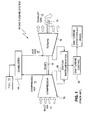
- FIG. 1 is a simple diagram showing the components of a typical gas turbine system 10.
- the gas turbine system 10 includes (i) a compressor 12, which compresses incoming air 11 to high pressure, (ii) a combustor 14, which bums fuel 13 so as to produce a high-pressure, high-velocity hot gas 17, and (iii) a turbine 16, which extracts energy from the high-pressure, high-velocity hot gas 17 entering the turbine 16 from the combustor 14, so as to be rotated by the hot gas 17.
- a shaft 18 connected to the turbine 16 and compressor 12 is caused to be rotated as well.
- exhaust gas 19 exits the turbine 16.
- the cycle conditions at various locations in the gas turbine are measured by long term instrumentation referred to as station instrumentation 36. This instrumentation provides input to the gas turbine's control system 42 which will change the gas turbine effectors as defined in the control laws.
- Figure 2 is a plan view of turbine 16's exhaust frame 20, looking aft.
- the exhaust frame 20 consists of an outer cylinder 22 and an inner cylinder 24 interconnected by a plurality of radially extending struts 26.
- the exhaust frame 20 typically receives a flow of exhaust gas 19 from turbine 16's exhaust diffuser (not shown).
- FIG. 2 there are a total of six radially extending struts 26 interconnecting outer cylinder 22 and an inner cylinder 24.
- Figure 3 is a partial perspective view in greater detail of one of the radially extending struts 26 interconnecting outer cylinder 22 and inner cylinder 24.
- Each of the struts 26 includes, relative to the exhaust gas 19 flowing from the turbine's exhaust diffuser, a leading edge 28 and a trailing edge 30.
- thermocouples 32 are installed along the skins 38 of the exhaust frame struts 26 at a number of positions extending radially from the inner cylinder 24.
- the thermocouples 32 shown in Fig. 3 are shown as being installed at multiple radial locations inside the skin 38 of each exhaust strut 26.
- the thermocouples 32 could be located, however, inside or outside the struts, and at the struts' leading and/or trailing edges.
- the thermocouple locations could also be a mixture of locations including inside and outside the struts, and at the struts' leading and trailing edges.
- Temperature data from the thermocouples 32 in each of the struts 26 is used to produce a normalized radial profile of the exhaust temperature of turbine 16.
- the turbine's existing station instrumentation 36 is then used to expand the normalized profile into the actual profile of the turbine's exhaust temperature.
- the turbine's existing station instrumentation 36 preferably includes a suitable computer system, which may be the gas turbine control system 42 for performing calculations used to develop profiles of the exhaust temperature of turbine 16.
- the calculations/transfer functions for temperatures are verified, or calibrated during performance testing with full rakes.
- This profile is integrated to determine a bulk Tx to improve model-based controls or corrected parameter controls (MBC/CPC) controls, or specific radial temperatures are used, to provide protective action for turbine bucket platforms, etc.
- computer system 42 would typically include a central processing unit (CPU) and system bus that would couple various computer components to the CPU.
- the system buses may be any of several types of bus structures, including a memory bus or memory controller, a peripheral bus, and a local bus using any of a variety of bus architectures.
- the memory used by computer system 42 would also typically include random access memory (RAM) and one or more hard disk drives that read from, and write to, (typically fixed) magnetic hard disks.
- RAM random access memory
- a basic input/output system (BIOS) containing the basic routines that help to transfer information between elements within a computer system, such as during start-up, may also be stored in read only memory (ROM).
- ROM read only memory
- Computer system 42 might also include other types of drives for accessing other computer-readable media, such as removable "floppy" disks, or an optical disk, such as a CD ROM.
- the hard disk, floppy disk, and optical disk drives are typically connected to a system bus by a hard disk drive interface, a floppy disk drive interface, and an optical drive interface, respectively.
- the drives and their associated computer-readable media provide nonvolatile storage of computer-readable instructions, data structures, program modules, and other data used by machines, such as computer system 42.
- Computer system 42 will also include an input/output (I/O) device (not shown) and/or a communications device (not shown) for connecting to external devices, such as thermocouples 32.
- I/O input/output
- communications device not shown
- I/O and communications devices may be internal or external, and are typically connected to the computer's system bus via a serial or parallel port interface.
- Computer system 42 may also include other typical peripheral devices, such as printers, displays and keyboards.
- printers such as printers, displays and keyboards.
- computer system 42 would include a display monitor (not shown), on which various information is displayed.
- thermocouples 32 are applied at a number of radial positions along the struts 26 of the exhaust frame 20 of the turbine 16. For robust operation, these thermocouples 32 measure the metal temperature inside the struts' skins 38. A transfer function is used to determine the difference between the metal temperature and the flow path temperature based on performance data from performance rakes and/or analysis. Given the limited number of exhaust struts 26, and lobed nature of the circumferential profile, variation swirl, etc., the thermocouples 32 are not used to define an absolute exhaust temperature. Rather, they are used to define a normalized radial profile that is used with the existing station instrumentation to calculate an actual radial profile.
- a transfer function is used to calculate flow path temperatures at each thermocouple 32. Additional processing (e.g., regression analysis or the like) of the radial temperatures from all struts 26 produces a normalized radial temperature profile. This approach addresses concerns of the circumferential distribution and measuring the radial profile at a limited number of circumferential locations.
- the station instrumentation 36 is used to expand or calibrate the normalized profile, which is then integrated into a bulk exhaust temperature, or could fed into protective control loops to avoid excessive temperature at bucket platforms or similar applications. Existing Tx measurements occur at one radial position, and a correction is applied to calculate a bulk exhaust temperature. That correction is not constant. It varies with load, combustor mode, etc.
- the method of the present invention achieves reliable data equivalent to a production rake by:
- Potential benefits of the present method include improved control of emissions, improved hot gas path and HRSG life, increased peak fire capability by adjusting splits to minimize temperature at critical locations.
- Technical advantages of the present method include improved input to model based control systems to improve model tuning and improved understanding of Tx into the HRSG.
Landscapes
- Engineering & Computer Science (AREA)
- Mechanical Engineering (AREA)
- General Engineering & Computer Science (AREA)
- Control Of Turbines (AREA)
- Measuring Temperature Or Quantity Of Heat (AREA)
Applications Claiming Priority (1)
| Application Number | Priority Date | Filing Date | Title |
|---|---|---|---|
| US13/104,250 US8965728B2 (en) | 2011-05-10 | 2011-05-10 | Exhaust strut radial temperature measurement |
Publications (2)
| Publication Number | Publication Date |
|---|---|
| EP2522818A2 true EP2522818A2 (fr) | 2012-11-14 |
| EP2522818A3 EP2522818A3 (fr) | 2018-03-07 |
Family
ID=46125202
Family Applications (1)
| Application Number | Title | Priority Date | Filing Date |
|---|---|---|---|
| EP12167194.5A Withdrawn EP2522818A3 (fr) | 2011-05-10 | 2012-05-08 | Mesure de température radiale d'entretoise d'échappement |
Country Status (3)
| Country | Link |
|---|---|
| US (1) | US8965728B2 (fr) |
| EP (1) | EP2522818A3 (fr) |
| CN (1) | CN102853943B (fr) |
Families Citing this family (10)
| Publication number | Priority date | Publication date | Assignee | Title |
|---|---|---|---|---|
| US9207128B2 (en) * | 2012-06-05 | 2015-12-08 | General Electric Company | Dynamic fiber temperature sensing package and method of assembling the same |
| US9528440B2 (en) | 2013-05-31 | 2016-12-27 | General Electric Company | Gas turbine exhaust diffuser strut fairing having flow manifold and suction side openings |
| US9494086B2 (en) | 2014-02-28 | 2016-11-15 | General Electric Company | Systems and methods for improved combined cycle control |
| CN105675158A (zh) * | 2016-01-06 | 2016-06-15 | 南京航空航天大学 | 一种同时测量燃气轮机燃烧室出口温度与燃烧产物浓度的装置及方法 |
| US10697316B2 (en) | 2017-12-18 | 2020-06-30 | Rolls-Royce North American Technologies Inc. | Apparatus and method for measuring turbine temperature |
| US11655737B2 (en) | 2020-07-30 | 2023-05-23 | General Electric Company | Heat exchanger with inner sensor grid and restraints for sensor wires and heat exchange tubes |
| FR3117213B1 (fr) * | 2020-12-08 | 2024-02-23 | Safran | Peigne d’instrumentation pour moteur d’aéronef à capteurs et électronique intégrés |
| US11994432B2 (en) * | 2021-09-13 | 2024-05-28 | Pratt & Whitney Canada Corp. | Method and system for detecting failure in an array of thermocouples connected in parallel |
| US12031490B2 (en) * | 2021-09-20 | 2024-07-09 | Ge Infrastructure Technology Llc | System and method for non-model based control utilizing turbine exit mach number surrogate |
| US12529325B1 (en) | 2025-07-29 | 2026-01-20 | Pratt & Whitney Canada Corp. | Turbine exhaust duct with stiffeners for aircraft engines |
Family Cites Families (8)
| Publication number | Priority date | Publication date | Assignee | Title |
|---|---|---|---|---|
| US2698872A (en) * | 1951-08-30 | 1955-01-04 | Gen Motors Corp | Thermocouple mount |
| US4765751A (en) * | 1987-06-29 | 1988-08-23 | United Technologies Corporation | Temperature and pressure probe |
| US6595062B1 (en) * | 2000-10-16 | 2003-07-22 | Lockheed Martin Corporation | High temperature rake for suspersonic flow |
| JP3960826B2 (ja) * | 2002-03-07 | 2007-08-15 | 株式会社荏原製作所 | ガスタービン装置及びその制御方法 |
| US6952639B2 (en) * | 2002-11-12 | 2005-10-04 | General Electric Company | Method and system for temperature estimation of gas turbine combustion cans |
| JP2008218449A (ja) | 2007-02-28 | 2008-09-18 | Dainippon Screen Mfg Co Ltd | 基板処理装置のスケジュール作成方法及びそのプログラム |
| US20090228230A1 (en) * | 2008-03-06 | 2009-09-10 | General Electric Company | System and method for real-time detection of gas turbine or aircraft engine blade problems |
| CN101825503B (zh) * | 2010-04-16 | 2011-07-06 | 东南大学 | 汽机表面式加热器的出水及疏水温度测算方法 |
-
2011
- 2011-05-10 US US13/104,250 patent/US8965728B2/en not_active Expired - Fee Related
-
2012
- 2012-05-08 EP EP12167194.5A patent/EP2522818A3/fr not_active Withdrawn
- 2012-05-10 CN CN201210143055.9A patent/CN102853943B/zh not_active Expired - Fee Related
Non-Patent Citations (1)
| Title |
|---|
| None |
Also Published As
| Publication number | Publication date |
|---|---|
| CN102853943A (zh) | 2013-01-02 |
| CN102853943B (zh) | 2016-12-21 |
| US8965728B2 (en) | 2015-02-24 |
| EP2522818A3 (fr) | 2018-03-07 |
| US20120290250A1 (en) | 2012-11-15 |
Similar Documents
| Publication | Publication Date | Title |
|---|---|---|
| US8965728B2 (en) | Exhaust strut radial temperature measurement | |
| CN104595038B (zh) | 多分管型燃烧室使用燃烧动态调谐算法的系统和方法 | |
| US8490404B1 (en) | Sensor-based performance-seeking gas turbine engine control | |
| EP2400118B1 (fr) | Système et procédé de gestion de la durée de vie d'aubes de turbomachine | |
| US6785633B2 (en) | Method and apparatus for assessing performance of combined cycle power-plants | |
| US8862433B2 (en) | Partitioning of turbomachine faults | |
| JP2005509794A5 (fr) | ||
| US10598041B2 (en) | Inlet performance measurement system for gas turbine engine | |
| US20110142602A1 (en) | Methods of determining variable element settings for a turbine engine | |
| EP2586998A2 (fr) | Capteurs de mesure disposés radialement dans une turbine | |
| EP3719256B1 (fr) | Système et procédé de réparation de composants d'aéronefs | |
| Jie et al. | A physics-based framework for online surface roughness assessment for high-pressure turbines | |
| Naik et al. | GT36 turbine development and full-scale validation | |
| D’ercole et al. | Results and experience from Ge energy’s MS5002e Gas Turbine Testing and evaluation | |
| Torkaman et al. | Gas turbine cycle upgrade and validation for heavy duty industrial machines | |
| Eulitz et al. | Design and validation of a compressor for a new generation of heavy-duty gas turbines | |
| US20250356085A1 (en) | Process of preparing a vane ring | |
| KR101930592B1 (ko) | 가스터빈 고온부품의 사용수명 산출 장치 및 방법 | |
| US20220357229A1 (en) | Methods of identifying unbalance of engine rotors based on engine vibration | |
| Kurzke et al. | Model based performance analysis | |
| RU2555950C2 (ru) | Турбореактивный двигатель | |
| Ko¨ rba¨ cher et al. | Development and validation of the new Alstom GT24/GT26 upgrade compressor | |
| Veerappan et al. | Shop testing of the W501FD gas turbine at the Berlin Test Facility | |
| Bessone et al. | Simplified method to evaluate the “under platform” damper effects on turbine blade eigenfrequencies supported by experimental test | |
| Bullard et al. | Case Study of Compressor Blade Tip Clearance and Implications to Operational Flexibility of an Industrial Gas Turbine |
Legal Events
| Date | Code | Title | Description |
|---|---|---|---|
| PUAI | Public reference made under article 153(3) epc to a published international application that has entered the european phase |
Free format text: ORIGINAL CODE: 0009012 |
|
| AK | Designated contracting states |
Kind code of ref document: A2 Designated state(s): AL AT BE BG CH CY CZ DE DK EE ES FI FR GB GR HR HU IE IS IT LI LT LU LV MC MK MT NL NO PL PT RO RS SE SI SK SM TR |
|
| AX | Request for extension of the european patent |
Extension state: BA ME |
|
| PUAL | Search report despatched |
Free format text: ORIGINAL CODE: 0009013 |
|
| AK | Designated contracting states |
Kind code of ref document: A3 Designated state(s): AL AT BE BG CH CY CZ DE DK EE ES FI FR GB GR HR HU IE IS IT LI LT LU LV MC MK MT NL NO PL PT RO RS SE SI SK SM TR |
|
| AX | Request for extension of the european patent |
Extension state: BA ME |
|
| RIC1 | Information provided on ipc code assigned before grant |
Ipc: F01D 21/00 20060101AFI20180126BHEP Ipc: F01D 25/30 20060101ALI20180126BHEP Ipc: F01D 21/12 20060101ALI20180126BHEP |
|
| STAA | Information on the status of an ep patent application or granted ep patent |
Free format text: STATUS: THE APPLICATION IS DEEMED TO BE WITHDRAWN |
|
| 18D | Application deemed to be withdrawn |
Effective date: 20180908 |