EP2522849A2 - Système de pompage d'eau - Google Patents
Système de pompage d'eau Download PDFInfo
- Publication number
- EP2522849A2 EP2522849A2 EP12003737A EP12003737A EP2522849A2 EP 2522849 A2 EP2522849 A2 EP 2522849A2 EP 12003737 A EP12003737 A EP 12003737A EP 12003737 A EP12003737 A EP 12003737A EP 2522849 A2 EP2522849 A2 EP 2522849A2
- Authority
- EP
- European Patent Office
- Prior art keywords
- water
- drive
- pump
- rocker
- container
- Prior art date
- Legal status (The legal status is an assumption and is not a legal conclusion. Google has not performed a legal analysis and makes no representation as to the accuracy of the status listed.)
- Withdrawn
Links
- XLYOFNOQVPJJNP-UHFFFAOYSA-N water Substances O XLYOFNOQVPJJNP-UHFFFAOYSA-N 0.000 title claims abstract description 99
- 238000005086 pumping Methods 0.000 title description 11
- 230000033001 locomotion Effects 0.000 claims abstract description 17
- 230000005540 biological transmission Effects 0.000 claims abstract description 5
- 238000007789 sealing Methods 0.000 claims description 2
- 239000012530 fluid Substances 0.000 claims 2
- 238000012423 maintenance Methods 0.000 description 8
- 230000008878 coupling Effects 0.000 description 6
- 238000010168 coupling process Methods 0.000 description 6
- 238000005859 coupling reaction Methods 0.000 description 6
- 238000010586 diagram Methods 0.000 description 3
- 238000002485 combustion reaction Methods 0.000 description 2
- 238000011109 contamination Methods 0.000 description 2
- 239000002245 particle Substances 0.000 description 2
- 230000003716 rejuvenation Effects 0.000 description 2
- 239000003643 water by type Substances 0.000 description 2
- 241001465754 Metazoa Species 0.000 description 1
- 230000001419 dependent effect Effects 0.000 description 1
- 239000003651 drinking water Substances 0.000 description 1
- 235000020188 drinking water Nutrition 0.000 description 1
- 230000005611 electricity Effects 0.000 description 1
- 230000005484 gravity Effects 0.000 description 1
- 210000003127 knee Anatomy 0.000 description 1
- 230000007257 malfunction Effects 0.000 description 1
- 238000000034 method Methods 0.000 description 1
- 230000001681 protective effect Effects 0.000 description 1
- 239000007787 solid Substances 0.000 description 1
- 239000008400 supply water Substances 0.000 description 1
Images




Classifications
-
- F—MECHANICAL ENGINEERING; LIGHTING; HEATING; WEAPONS; BLASTING
- F04—POSITIVE - DISPLACEMENT MACHINES FOR LIQUIDS; PUMPS FOR LIQUIDS OR ELASTIC FLUIDS
- F04B—POSITIVE-DISPLACEMENT MACHINES FOR LIQUIDS; PUMPS
- F04B9/00—Piston machines or pumps characterised by the driving or driven means to or from their working members
- F04B9/02—Piston machines or pumps characterised by the driving or driven means to or from their working members the means being mechanical
-
- F—MECHANICAL ENGINEERING; LIGHTING; HEATING; WEAPONS; BLASTING
- F04—POSITIVE - DISPLACEMENT MACHINES FOR LIQUIDS; PUMPS FOR LIQUIDS OR ELASTIC FLUIDS
- F04B—POSITIVE-DISPLACEMENT MACHINES FOR LIQUIDS; PUMPS
- F04B17/00—Pumps characterised by combination with, or adaptation to, specific driving engines or motors
-
- F—MECHANICAL ENGINEERING; LIGHTING; HEATING; WEAPONS; BLASTING
- F04—POSITIVE - DISPLACEMENT MACHINES FOR LIQUIDS; PUMPS FOR LIQUIDS OR ELASTIC FLUIDS
- F04B—POSITIVE-DISPLACEMENT MACHINES FOR LIQUIDS; PUMPS
- F04B9/00—Piston machines or pumps characterised by the driving or driven means to or from their working members
- F04B9/08—Piston machines or pumps characterised by the driving or driven means to or from their working members the means being fluid
- F04B9/10—Piston machines or pumps characterised by the driving or driven means to or from their working members the means being fluid the fluid being liquid
-
- Y—GENERAL TAGGING OF NEW TECHNOLOGICAL DEVELOPMENTS; GENERAL TAGGING OF CROSS-SECTIONAL TECHNOLOGIES SPANNING OVER SEVERAL SECTIONS OF THE IPC; TECHNICAL SUBJECTS COVERED BY FORMER USPC CROSS-REFERENCE ART COLLECTIONS [XRACs] AND DIGESTS
- Y02—TECHNOLOGIES OR APPLICATIONS FOR MITIGATION OR ADAPTATION AGAINST CLIMATE CHANGE
- Y02E—REDUCTION OF GREENHOUSE GAS [GHG] EMISSIONS, RELATED TO ENERGY GENERATION, TRANSMISSION OR DISTRIBUTION
- Y02E10/00—Energy generation through renewable energy sources
- Y02E10/30—Energy from the sea, e.g. using wave energy or salinity gradient
Definitions
- the present invention relates to a system for conveying water according to the preamble of patent claim 1 and a drive for such a system according to the preamble of claim 12.
- ES 2234391 and US 1 260 204 disclose systems with water-powered rockers for generating electricity or for driving an engine.
- the inventive system for conveying water has a pump for conveying the water and a pump drive for driving the pump.
- the inventive pump drive according to the invention is a water-actuated rocker. This rocker is operatively connected to a drive axis of the pump, so that a pivoting movement of the rocker has a drive movement of the drive axle result.
- water of the same origin for the drive, from which the water should also be conveyed by means of the pump.
- This origin is preferably a stream or a river. If the source is a lake, a pond, a pool of water or some other still water, an outflow from that body of water is usually used to extract water to operate the seesaw.
- the water which is to be conveyed by means of the pump can also have a different origin than that for the rocker.
- the pump can pump clean water and the rocker can be operated with dirty water.
- connection between rocker and drive axle can be done directly by the drive shaft is attached by suitable means to the rocker. It can be firmly connected to the rocker.
- the connection can also be made indirectly via gearboxes, connecting rods or other suitable means, in particular via detachable couplings.
- the pump for conveying the water is preferably a piston pump, although other types of mechanically driven pumps can be used.
- Piston pumps have the advantage that they are relatively low maintenance and also easy to maintain.
- a multi-piston pump in particular a two-piston pump is used.
- This pump has a relatively high flow rate.
- the drive axis of the pump is preferably connected to the pivot axis of the rocker, preferably pivotal movements of the rocker are converted in both directions in a piston movement of the pump and thus in a delivery stroke.
- a suitable transmission means of known type can be used in the coupling part between the drive axle and the pivot axle.
- the pump is formed by one or more single piston pumps.
- This embodiment has the advantage that the individual pumps are inexpensive and are extremely easy to maintain. If more than one single-piston pump is used, the system will still work if one of these pumps fails. If single-piston pumps are used, their piston rods are preferably connected to one arm of the rocker at a location spaced from the pivot axis of the rocker.
- the rocker is driven as follows: the rocker has a beam pivotally mounted on a base and having a first free end, a water collecting container being arranged at this first free end. Furthermore, a water pipe for automatically filling the container is present when the container is in a upper position of the first free end is located. Further, there is a means for emptying the container when it is in a lower position of the first free end.
- the rocker already works with a single water tank at one end of the beam.
- a counterweight is preferably present at the other end to bring the container back to its raised position after emptying.
- the beam has two free ends, wherein a water collecting container is arranged at both free ends.
- These two water collectors are alternately automatically filled with water and alternately automatically emptied again, so they mutually form the counterweights to bring the empty containers back to the raised position.
- the water collecting container preferably has on its underside an opening which is spring-loaded after emptying again closed. In this way, the container can form completely closed except for a filling inlet and an emptying outlet. It is also possible to force a filled, preferably open-topped container in a pivoting movement to empty it.
- the filling of the containers takes place along the beam.
- the water pipe can be attached to the beam.
- the beam itself is hollow and thus forms the water pipe itself.
- connection for connection to a water-supplying drive line is present.
- this connection is located in a plane passing through the pivot axis. In this way, a single valve can be used, on the one hand to block the supply of water in one container and to allow in the other container.
- a valve is present, which permits a fluid-communicating connection between a first of the water collecting container and the drive line and a fluidkommunitudede Interrupt connection between the second of the water collecting container and the drive line and alternately the fluid-communicating connection between the first water collecting container and the drive line permits and interrupts the fluid-communicating connection between the second water collecting container and the drive line.
- this valve is formed by a ball, wherein the water line in the beam tapers from the pivot axis to the water collection containers at one point, so that the ball during rocking of the beam between these two tapered points rolls back and forth and alternately sealing these rejuvenated areas.
- This embodiment has the advantage that the valve is virtually maintenance-free. In case of malfunction, the ball can be easily removed or cleaned. Replacement balls are easy to find or produce.
- a window in the water pipe, in particular in the beam, which is arranged in the region of the valve, allows a regular check of the wear of the ball and the pollution of this area of the water pipe.
- another closure element e.g. one or more flaps are used.
- the drive according to the invention is not only suitable for driving pumps which themselves are used to convey water. It is also suitable as a drive for differently used pumps and / or mechanical drives, for example for alternators or other pumps used especially in third world countries or remote regions.
- FIGS. 1 to 4 a first embodiment of the inventive system is shown. From a flowing water, especially a river or a small mountain stream, water is taken, as in FIG. 1 is recognizable.
- an opening of a line, here called drive line 1 placed in the river.
- the opening is closed with a particle sieve 10, so that no larger solids can get into the conduit 1.
- the drive line 1 leads to a rocker 7. It is sealingly coupled to the rocker 7. This can be done for example by means of a connecting flange 72. Preferably, this is a radial shaft seal, also called Simmerring used.
- the system further comprises a pump 3, which supplies water from a supply line 2 into one Pumping line 4 should promote.
- the water of the pumping line 4 can be used directly or it can lead to a reservoir 5, a so-called high tank or pump tank.
- the pumping tank 5 is usually higher than the location of the drive line 1 in the flowing waters. From this reservoir 5, a utility line 6 carries water under pressure to the user.
- the supply line 2 may be a branch of the pumping line 1. However, it may also carry water from another location of the same flowing body of water. Alternatively or additionally, it may also pass water from other waters, in particular a stagnant water, a deep well or a basin.
- the supply line 2 is preferably provided with a closer 20 in order to interrupt the supply of water into the pump 3. This is especially helpful during maintenance.
- the closer 20 may for example be a simple slide or a ball valve.
- the pumping line 4 is preferably closable with a closer 40. The nature of the lock and the reason of its arrangement is the same as in the first closing 20.
- the drive line 1 may be provided with a Schliesser.
- a pressure gauge 41 is preferably arranged, which measures the pressure in the pump line 4.
- the pump 3 shown here is a piston pump, in particular a pump with two mutually conveying piston 30. That is, they are alternatively raised and lowered, so that water is continuously pumped through the pump. It is also possible to use other types of pumps, whereby the water does not necessarily have to pass through the pump.
- the drive shaft 31 of the pump 3 is mechanically operatively connected to the rocker 7. A rocking movement of the rocker 7 causes the drive shaft 31 is moved and so the pump 3 is actuated.
- the drive shaft 31 may be mechanically connected directly or via a transmission unit 8 with the pivot axis 781 of the rocker 7.
- the transfer unit 8 can, as shown in Figure 8, be a simple flange, which connects the two axes 781, 31 together. But it may also include, for example, a gearbox or a motion converter.
- the rocker 7 is in FIG. 2 shown in detail. It has a bar 73 which is pivotally mounted on a bearing block 70.
- the bearing block 70 is preferably firmly anchored in the ground.
- a pivot axis 781 of the beam 73 is pivotally supported in a bearing 780 of the bearing block 70.
- the bar 73 is divided on both sides of the pivot axis in each case an arm 730, 731.
- the arms 730, 731 are preferably the same length or the pivot axis is preferably in the center of gravity of the beam 73rd
- Both arms 730, 731 each have a free end, to each of which a water collecting container 74, 74 'is arranged.
- the beam 73 is hollow and connects these water tank 74, 74 'with the drive line 1.
- the bar 73 thus represents an internal wippen water pipe.
- the connection of bar 73 with the drive line 1 is preferably carried out in the plane of the pivot axis.
- the water pipe of the beam 73 has in the region of the pivot axis of the rocker a larger inner diameter than in the region of the container 74, 74 '.
- the rejuvenation can be continuous.
- a clearly defined step is provided in both arms 730, 731, which serves as a valve seat for a valve ball 75.
- This valve ball 75 rolls during the rocking movement of the beam 73 between these two valve seats back and forth. This closes depending on the position of the bar 73 one or the other arm 730, 731 and leaves the alternative arm 730, 731 open. Water thus flows from the drive line 1 through the bar 73 into the respective higher water collecting container 74 '. In FIG. 2 this is shown with an arrow.
- a suitable choice takes into account the flow of the flowing water in combination with the relative altitude of the upper tank 74 'to the location of the drive line 1 in the water, so that the water actually through the above Line system in the raised container 74 'flows.
- This opening 740 is closed when the container 74 'is raised and opened when the container 74 is lowered.
- the opening 740 is preferably located at a lower location of the container 74, 74 '.
- the effluent from the container 74, 74 'water can be recycled to the flowing water. It can also be used elsewhere.
- the opening 740 can be closed in different ways and opened automatically.
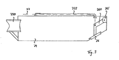
- a closure flap 76, 76 ' is provided, which is arranged in the interior of the container 74, 74'.
- This closure flap 76, 76 ' is pivotally mounted via a knee lever 760, 760' in a pivot bearing 761, 761 '.
- a return spring 770, 770 ' is arranged at an operating line 77.
- the return spring 770, 770 'on the pivot axis 781 opposite side of the bearing block 70 is arranged.
- the return spring 770 is connected to the cord 77 and thus to the closure flap 76. Thanks to this arrangement, the flap 76 opens when lowering the container 74. It releases the opening 740. The water can flow out of the container 74. At the same time, the flap 76 'of the other container 74' closes while it is being lifted. The raised container 74 'can thus be filled.
- a protective tube 772 In order for the cord 77 not to wear too quickly, it is preferably at least partially guided in a protective tube 772, as shown in FIG FIG. 3 is shown.
- a flange cover 71 with viewing window is preferably present (see FIG. 1 ). If maintenance is necessary, only the flange cover 71 needs to be removed.
- the pivot axis 781 of the rocker 7 thereby pivots back and forth and transmits this rotational movement directly or translated to the drive shaft 31, which drives the pump 3. Water is thus pumped from the supply line 2 into the pumping line 4.
- the drive line 1 has a substantially larger diameter than the feed line 2.
- FIG. 5 an alternative way of supplying water into the rocker 7 is shown.
- the drive line is at least partially formed by a tube 1. This ends via a raised container 74 'of the rocker 7.
- a connecting tube 11 is attached on the bar 73 of the rocker 7. This extends at an angle to the beam 73 so that the connecting tube 11, when the other container 74 is raised, connects to the first tube 1 and has a slight slope from the first tube 1 to the raised second container 74.
- the connecting tube 11 is secured by correspondingly different lengths supports 12, 12 ', 12 "on the beam 73.
- the connecting pipe 11 ends with its mouth 110 above this second container 74, so that it can fill the container 74.
- a coupling part for automatic coupling with the pipe 1 is mounted or the end is shaped accordingly.
- FIG. 6 is another pump shown.
- This has two or more single-piston pumps 32, 32 ', which are spaced from the pivot axis 781 of the rocker 7 with the arms 730, 731 of the rocker 7 mechanically operatively connected.
- the piston rods of the pumps 32, 32 ' With the arms 730, 731 firmly connected.
- the piston pumps 32, 32 ' can thus convey water from a supply line 2 into a pressure line 4.
- the water can be taken at the same point over a single line for both the drive line 1 as well as for the supply line 2.
- a separate version is shown, so that the supply line 2 is provided with a sieve 21.
- FIG. 6 an alternative form of the containers 74, 74 'can be seen.
- a spring-loaded outlet valve 79, 79 ' is arranged in the containers 74, 74' instead of the closure flap 76, 76 '.
- the valve body here in the form of a truncated cone, closes the opening, but protrudes downwards out of this. If now the container 74, 74 'on the ground, so the valve body is pressed against a spring force in the container 74, 74' in and gives the outlet opening of the Container 74, 74 'free.
- This embodiment has the advantage that no operating cords must be used.
- the closure caps 76, 76 ' have the advantage that the containers 74, 74' do not have to rest on the ground in order to be emptied.
- the system according to the invention and the pump drive according to the invention make it possible to supply water with the simplest possible means, as maintenance-free as possible.
Landscapes
- Engineering & Computer Science (AREA)
- Mechanical Engineering (AREA)
- General Engineering & Computer Science (AREA)
- Structures Of Non-Positive Displacement Pumps (AREA)
- Details Of Reciprocating Pumps (AREA)
Applications Claiming Priority (1)
| Application Number | Priority Date | Filing Date | Title |
|---|---|---|---|
| ATA678/2011A AT511101B1 (de) | 2011-05-12 | 2011-05-12 | System zum fördern von wasser |
Publications (2)
| Publication Number | Publication Date |
|---|---|
| EP2522849A2 true EP2522849A2 (fr) | 2012-11-14 |
| EP2522849A3 EP2522849A3 (fr) | 2017-05-31 |
Family
ID=46147249
Family Applications (1)
| Application Number | Title | Priority Date | Filing Date |
|---|---|---|---|
| EP12003737.9A Withdrawn EP2522849A3 (fr) | 2011-05-12 | 2012-05-10 | Système de pompage d'eau |
Country Status (2)
| Country | Link |
|---|---|
| EP (1) | EP2522849A3 (fr) |
| AT (1) | AT511101B1 (fr) |
Citations (2)
| Publication number | Priority date | Publication date | Assignee | Title |
|---|---|---|---|---|
| US1260204A (en) | 1917-05-08 | 1918-03-19 | James M Keithly | Water-operated motor. |
| ES2234391A1 (es) | 2003-03-26 | 2005-06-16 | Antonio Oblanca Martinez | Balancin hidraulico para generar electricidad. |
Family Cites Families (3)
| Publication number | Priority date | Publication date | Assignee | Title |
|---|---|---|---|---|
| US836504A (en) * | 1905-12-12 | 1906-11-20 | Alfred E Jones | Water-actuated pumping apparatus. |
| US1466861A (en) * | 1921-07-06 | 1923-09-04 | Tuttle Merritt Isaac | Water-power motor |
| FR836218A (fr) * | 1938-04-05 | 1939-01-12 | Moteur hydraulique utilisant de faibles chutes d'eau |
-
2011
- 2011-05-12 AT ATA678/2011A patent/AT511101B1/de not_active IP Right Cessation
-
2012
- 2012-05-10 EP EP12003737.9A patent/EP2522849A3/fr not_active Withdrawn
Patent Citations (2)
| Publication number | Priority date | Publication date | Assignee | Title |
|---|---|---|---|---|
| US1260204A (en) | 1917-05-08 | 1918-03-19 | James M Keithly | Water-operated motor. |
| ES2234391A1 (es) | 2003-03-26 | 2005-06-16 | Antonio Oblanca Martinez | Balancin hidraulico para generar electricidad. |
Also Published As
| Publication number | Publication date |
|---|---|
| AT511101A4 (de) | 2012-09-15 |
| EP2522849A3 (fr) | 2017-05-31 |
| AT511101B1 (de) | 2012-09-15 |
Similar Documents
| Publication | Publication Date | Title |
|---|---|---|
| DE2357143A1 (de) | Membranpumpe und druckregel- und entlastungsventil | |
| WO2014019642A1 (fr) | Élément de remplissage et machine de remplissage | |
| DE2308460A1 (de) | Ventil | |
| DE29610900U1 (de) | Kugelschleuse für eine Einrichtung zum Rückführen von Kugeln zum Reinigen der Rohre von Kühlsystemen | |
| WO1985000413A1 (fr) | Installation de pompage d'eau | |
| AT511101B1 (de) | System zum fördern von wasser | |
| DE2357023A1 (de) | Vorrichtung zur reinigung von bierzapfanlagen | |
| DE4239420A1 (en) | Piston fluid pump - has two chambers divided by movable wall allowing variable compressed volumes in both chambers | |
| EP2224069B1 (fr) | Système de montage transportant du fluide | |
| DE583147C (de) | Luftableitungs- und Leckfluessigkeitsableitvorrichtung bei Kolbenfluessigkeitsmessern | |
| DE102010005778A1 (de) | Vorrichtung zum selbsttätigen Verschließen eines Zulaufes eines Behälters zur Aufnahme einer Flüssigkeit und Abscheidevorrichtung | |
| DE102419C (fr) | ||
| DE19610697A1 (de) | Fußstück | |
| DE58036C (de) | Zweikammerige Vorrichtung zum Heben von Flüssigkeiten durch Druckluft | |
| DE63493C (de) | Wassersäulenmaschine mit zwei Cylindern und durch das verbrauchte Wasser bewegtem schwingenden Steuerhebel | |
| DE85777C (fr) | ||
| DE48197C (de) | Als Pumpe wirkender Dampfwasser-Abieiter | |
| AT279366B (de) | Pumpeinrichtung für Tiefbrunnen | |
| DE3526758A1 (de) | Selbsttaetiges fluessigkeits-hebewerk | |
| DE28680C (de) | Neuerungen an Schmiervorrichtung gen | |
| DE698713C (de) | Zweikammeriger Druckluftfluessigkeitscheber | |
| AT500413B1 (de) | Einlaufeinheit für ein bis zu einem bestimmten niveau zu füllendes gefäss | |
| DE231861C (fr) | ||
| AT18820B (de) | Faßfüllvorrichtung mit Einrichtung zum selbsttätigen Abgleichen der durch das Füllrohr aus dem Fasse verdrängten Biermenge. | |
| AT33927B (de) | Pumpe mit Kolbendichtung durch einen Flüssigkeitsstrahl. |
Legal Events
| Date | Code | Title | Description |
|---|---|---|---|
| PUAI | Public reference made under article 153(3) epc to a published international application that has entered the european phase |
Free format text: ORIGINAL CODE: 0009012 |
|
| AK | Designated contracting states |
Kind code of ref document: A2 Designated state(s): AL AT BE BG CH CY CZ DE DK EE ES FI FR GB GR HR HU IE IS IT LI LT LU LV MC MK MT NL NO PL PT RO RS SE SI SK SM TR |
|
| AX | Request for extension of the european patent |
Extension state: BA ME |
|
| PUAL | Search report despatched |
Free format text: ORIGINAL CODE: 0009013 |
|
| AK | Designated contracting states |
Kind code of ref document: A3 Designated state(s): AL AT BE BG CH CY CZ DE DK EE ES FI FR GB GR HR HU IE IS IT LI LT LU LV MC MK MT NL NO PL PT RO RS SE SI SK SM TR |
|
| AX | Request for extension of the european patent |
Extension state: BA ME |
|
| RIC1 | Information provided on ipc code assigned before grant |
Ipc: F04B 9/02 20060101ALI20170425BHEP Ipc: F04B 17/00 20060101ALI20170425BHEP Ipc: F04B 9/10 20060101ALI20170425BHEP Ipc: F03B 13/18 20060101AFI20170425BHEP |
|
| STAA | Information on the status of an ep patent application or granted ep patent |
Free format text: STATUS: THE APPLICATION IS DEEMED TO BE WITHDRAWN |
|
| 18D | Application deemed to be withdrawn |
Effective date: 20171201 |