EP2522860B1 - Hydraulic distributor having a connection parallel to the recesses adjusting the flow rate of the slide and to the local compensator - Google Patents
Hydraulic distributor having a connection parallel to the recesses adjusting the flow rate of the slide and to the local compensator Download PDFInfo
- Publication number
- EP2522860B1 EP2522860B1 EP20120167550 EP12167550A EP2522860B1 EP 2522860 B1 EP2522860 B1 EP 2522860B1 EP 20120167550 EP20120167550 EP 20120167550 EP 12167550 A EP12167550 A EP 12167550A EP 2522860 B1 EP2522860 B1 EP 2522860B1
- Authority
- EP
- European Patent Office
- Prior art keywords
- channel
- slide
- flow rate
- shutter
- pressure
- Prior art date
- Legal status (The legal status is an assumption and is not a legal conclusion. Google has not performed a legal analysis and makes no representation as to the accuracy of the status listed.)
- Not-in-force
Links
- 238000006073 displacement reaction Methods 0.000 claims description 8
- 230000001105 regulatory effect Effects 0.000 claims description 5
- 238000007599 discharging Methods 0.000 claims description 2
- 238000007789 sealing Methods 0.000 claims description 2
- 238000011144 upstream manufacturing Methods 0.000 description 5
- 238000010586 diagram Methods 0.000 description 3
- 238000000034 method Methods 0.000 description 3
- 230000001419 dependent effect Effects 0.000 description 2
- 230000035939 shock Effects 0.000 description 2
- 230000001276 controlling effect Effects 0.000 description 1
- 230000003247 decreasing effect Effects 0.000 description 1
- 239000003344 environmental pollutant Substances 0.000 description 1
- 231100000719 pollutant Toxicity 0.000 description 1
- 230000000750 progressive effect Effects 0.000 description 1
- 230000003068 static effect Effects 0.000 description 1
Images

Classifications
-
- F—MECHANICAL ENGINEERING; LIGHTING; HEATING; WEAPONS; BLASTING
- F15—FLUID-PRESSURE ACTUATORS; HYDRAULICS OR PNEUMATICS IN GENERAL
- F15B—SYSTEMS ACTING BY MEANS OF FLUIDS IN GENERAL; FLUID-PRESSURE ACTUATORS, e.g. SERVOMOTORS; DETAILS OF FLUID-PRESSURE SYSTEMS, NOT OTHERWISE PROVIDED FOR
- F15B11/00—Servomotor systems without provision for follow-up action; Circuits therefor
- F15B11/16—Servomotor systems without provision for follow-up action; Circuits therefor with two or more servomotors
- F15B11/161—Servomotor systems without provision for follow-up action; Circuits therefor with two or more servomotors with sensing of servomotor demand or load
- F15B11/165—Servomotor systems without provision for follow-up action; Circuits therefor with two or more servomotors with sensing of servomotor demand or load for adjusting the pump output or bypass in response to demand
-
- F—MECHANICAL ENGINEERING; LIGHTING; HEATING; WEAPONS; BLASTING
- F15—FLUID-PRESSURE ACTUATORS; HYDRAULICS OR PNEUMATICS IN GENERAL
- F15B—SYSTEMS ACTING BY MEANS OF FLUIDS IN GENERAL; FLUID-PRESSURE ACTUATORS, e.g. SERVOMOTORS; DETAILS OF FLUID-PRESSURE SYSTEMS, NOT OTHERWISE PROVIDED FOR
- F15B11/00—Servomotor systems without provision for follow-up action; Circuits therefor
- F15B11/16—Servomotor systems without provision for follow-up action; Circuits therefor with two or more servomotors
- F15B11/161—Servomotor systems without provision for follow-up action; Circuits therefor with two or more servomotors with sensing of servomotor demand or load
- F15B11/163—Servomotor systems without provision for follow-up action; Circuits therefor with two or more servomotors with sensing of servomotor demand or load for sharing the pump output equally amongst users or groups of users, e.g. using anti-saturation, pressure compensation
-
- F—MECHANICAL ENGINEERING; LIGHTING; HEATING; WEAPONS; BLASTING
- F15—FLUID-PRESSURE ACTUATORS; HYDRAULICS OR PNEUMATICS IN GENERAL
- F15B—SYSTEMS ACTING BY MEANS OF FLUIDS IN GENERAL; FLUID-PRESSURE ACTUATORS, e.g. SERVOMOTORS; DETAILS OF FLUID-PRESSURE SYSTEMS, NOT OTHERWISE PROVIDED FOR
- F15B2211/00—Circuits for servomotor systems
- F15B2211/20—Fluid pressure source, e.g. accumulator or variable axial piston pump
- F15B2211/205—Systems with pumps
- F15B2211/2053—Type of pump
- F15B2211/20546—Type of pump variable capacity
-
- F—MECHANICAL ENGINEERING; LIGHTING; HEATING; WEAPONS; BLASTING
- F15—FLUID-PRESSURE ACTUATORS; HYDRAULICS OR PNEUMATICS IN GENERAL
- F15B—SYSTEMS ACTING BY MEANS OF FLUIDS IN GENERAL; FLUID-PRESSURE ACTUATORS, e.g. SERVOMOTORS; DETAILS OF FLUID-PRESSURE SYSTEMS, NOT OTHERWISE PROVIDED FOR
- F15B2211/00—Circuits for servomotor systems
- F15B2211/20—Fluid pressure source, e.g. accumulator or variable axial piston pump
- F15B2211/25—Pressure control functions
- F15B2211/253—Pressure margin control, e.g. pump pressure in relation to load pressure
-
- F—MECHANICAL ENGINEERING; LIGHTING; HEATING; WEAPONS; BLASTING
- F15—FLUID-PRESSURE ACTUATORS; HYDRAULICS OR PNEUMATICS IN GENERAL
- F15B—SYSTEMS ACTING BY MEANS OF FLUIDS IN GENERAL; FLUID-PRESSURE ACTUATORS, e.g. SERVOMOTORS; DETAILS OF FLUID-PRESSURE SYSTEMS, NOT OTHERWISE PROVIDED FOR
- F15B2211/00—Circuits for servomotor systems
- F15B2211/30—Directional control
- F15B2211/305—Directional control characterised by the type of valves
- F15B2211/30525—Directional control valves, e.g. 4/3-directional control valve
- F15B2211/3053—In combination with a pressure compensating valve
- F15B2211/30555—Inlet and outlet of the pressure compensating valve being connected to the directional control valve
Definitions
- the pump is a variable displacement pump and supplies only the flow rate effectively required by the actuators.
- the control of the pump displacement is performed by a feedback of the pressure signal of the greater among the loads, called load sensing signal, or LS, from the distributor to the pump.
- the hydraulic distributor is also of the load sensing type.
- the pump adjusts its displacement by a regulator of the LS signal so that to keep constant the pressure differential between the delivery and the load sensing signal, or LS; such pressure differential will be called "LS ⁇ P".
- LS ⁇ P the pressure differential between the delivery and the load sensing signal
- the flow rate delivered to an actuator is adjusted as a function of the position of a movable slide by exploiting the drop pressure at the ends of recesses adjusting the flow rate which is kept constant independently from the load.
- load sensing distributors are used for adjusting the flow rate independently from the load for proportionally reducing the flow rates in active sections in case the flow rate required by the actuators is greater than the maximum one supplied by the pump.
- each operative section it is present a local pressure compensator which sets the pressure differential at the flow rate adjusting recesses equal to said LS ⁇ P in each operative section when the operation of two or more operative sections are driven also when the LS ⁇ P drops below the value set by the pump LS regulator.
- variable displacement pump there is a device for limiting the power absorbed by the pump itself for preventing the engine from turning off.
- the device operates as follows: when the delivery pressure increases, the maximum flow rate delivered from the pump is decreased by approximating a hyperbolic curve at constant power in the flow rate-pressure plane.
- the power regulator When the power regulator is operated, it overcomes the LS regulator which keeps constant LS ⁇ P, as a consequence LS ⁇ P is reduced with respect to the value at which the LS regulator was adjusted.
- patent EP1628018 (B1 ), in the name of the same Applicant, discloses an arrangement wherein the local compensator is downstream the flow rate adjusting recesses of the slide, and in the same lapped hole two components, a local compensator having a selector and a piston with a pushing device, slide.
- the group formed by the local compensator with selector and piston with pushing device forms a non-return valve selector; the selector generates the load sensing signal LS: the selector, kept opened by the pushing device, connects the signal downstream the flow rate adjusting recesses of the slide to the signal LS channel.
- the signal LS arrives at the pump regulator LS, then it acts between the local compensator with a selector and the piston with the pushing device of the other sections.
- the piston with the pushing device abuts a plug and compresses a spring, while the local compensator chokes the flow passage directed to the utilisation by making equal the pressure downstream the flow rate adjusting recesses to the LS pressure in channel 4.
- the selector is closed.
- a small-sized excavator comprising:
- Patent EP2184495 (A1 ) of the same Applicant discloses a method for limiting the maximum power required by the hydraulic circuit and different methods for obtaining this object.
- the method consists of providing a connection between the upstream and downstream channels of the local compensator in the sections of the translation.
- the connection must be suitable sized so that when a third actuator arrives at its limit stop, the power delivered from the pump (which is supplied to the two translation engines and which flows through the two connections) does not increase the pressure besides a limit at which the power limiter operates. In this way, it is not reduced the machine translation speed.
- the invention consists in an hydraulic distributor having an inlet channel from the pump, an output channel connected to a tank, a plurality of operative portions adapted to supply the actuators through corresponding utilisations by inner slides capable of diverting the flows to channels inside the distributor; local pressure compensators capable of controlling the pressure drop at the ends of the recesses adjusting the flow rate of the slide, so that the flow rate supplied by the slide is independent from the load, wherein it is present a connection between the channel receiving the oil from the pump and the channel delivering the oil to the actuator, closed in a central position of the slide, and that opens as a function of the position of the slide itself, such connection being parallel to the flow path through the recesses adjusting the flow rate of the slide and the local compensator.
- Said additional connection enables the oil to flow through a shutter, provided with a set spring, so that the opening pressure is greater than the set one of the pump regulator LS.
- connection is operative in one of the two positions of the slide or in both according to the fact if it is necessary to limit the speed of one or both the utilisations of the section.
- the present invention obtains the same operations of the connection disclosed by patent EP2184495 (A1 ) without having the above mentioned disadvantages, in fact it is present a suitable set non-return valve along the connection and such non-return valve is not usually supplied by the power flow.
- 2 generally indicates a load sensing distributor 2 comprising inside a channel 10 in which flows pressurized oil from a variable displacement pump 1; through said channel 10 the pressurised oil flows through suitable inner channels and can arrive to at least two portions A and B, each of them controls corresponding actuators 3A, 3B, through the channels or utilisations 13A, 14A (in the portion A) and 13B, 14B (in the portion B); the utilisations are in turn connected to the collecting tank through a cannel 15.
- the distributor 2 further comprises a pressure limiting valve 5 located in a load sensing signal channel 4 (LS) of the greater one among the loads and a flow rate regulating valve 6 for draining said LS signal channel 4.
- LS load sensing signal channel 4
- Each operative portion A and B is defined by an element 50A, 50B which receives the slides, local compensators and other components necessary for implementing the invention.
- the oil from the pump 1 encounters a slide 7A, passes through the area of the flow rate adjusting recesses 27A (23A) when the slide 7A is driven by V1A (V2A), passes through a local compensator 8A, to the utilisation 13A (14A), and returns to the utilisation 14A (13A) and drains itself through the channel 15.
- a piston 9A with a pushing device 28A slides in the same lapped hole of the local compensator 8A.
- the local compensator 8A receives a selector 18A for selecting the signal LS.
- the local compensator is normally closed; on one of its side it is subjected to a pressure upstream present at 11A which acts when it is opened through the channel 16A, from the other side it is subjected to the signal LS 4 and to the contact force of piston 9A which act to close.
- Piston 9A is subjected, on one side, to the pressure of channel 4 of signal LS and to the contact force of the local compensator 8A, on the other side to the pressure downstream present at 12A through the channel 24A and to the force of a spring 19A having a negligible value.
- portion A When just the portion A is operated or when is operated with other portions and has the greatest utilisation load (portion A is predominant), the local compensator 8A is opened and contacts the piston 9A because the pressure in 16A is greater than the pressure in 24A; the group formed by the local compensator 8A and piston 9A operates as a non-return valve.
- Signal LS is taken by channel 11A through channel 17A and is delivered to channel 4 through the selector 18A kept opened by the pushing device 28A of piston 9A.
- the pressure drop through the flow rate adjusting recesses 27A (23A) of the slide 7A between 10 and 11A is controlled by the pump and is equal to "LS ⁇ P", in other words the difference between the pressure in channel 10 and pressure in channel 4.
- portion A When portion A is operated with other portions and has the utilisation load which is not the highest, the local compensator 8A chokes the passage of the flow rate directed to the actuator 3A, so that the pressure in channel 16A is equal to pressure LS in channel 4; piston 9A is pushed to contact the spring 19A side and does not contact the local compensator 8A.
- the pressure drop through the flow rate adjusting recesses 27A (23A) of slide 7A between 10 and 11A is controlled by the local compensator 8A and also in this case is equal to "LS ⁇ P".
- a distributor having the portions as portion A, provides flow rates independent from the load and reduces them proportionally in case the flow rate required by the actuators is greater than the maximum one supplied by the pump, because the pressure drop at the ends of the flow rate adjusting recesses is equal to "LS ⁇ P" in all the sections.
- the oil from pump 1 encounters the slide 7A, passes through the area of the recesses, for adjusting the flow rate 27B (23B) when the slide 7B is driven by V1B (V2B), passes through the local compensator 8B, arrives to the utilisation 13B (14B), returns to the utilisation 14B (13B) and discharges itself through channel 15.
- shock-resistant and anti-cavitation secondary valves 25B and 25B in channels 13B and 14B are shock-resistant and anti-cavitation secondary valves 25B and 25B in channels 13B and 14B.
- portion B the group formed by the local compensator 8B having the selector 8B, piston 9B with a pushing device 28B and spring 19B, is analogous to the one of portion A, therefore the description is the same.
- connection 20 Between the connection 20 there is a shutter 21 kept in position by the closing position of a spring 22 set so that the opening pressure of the shutter 21 is greater than "LS ⁇ P" established by the pump regulator LS.
- connection 20 When the slide 7B is driven by V2B, the connection 20 remains closed, as when the slide is in a central position, so that in this case the operation of the portion is the same as the operation of the above described portion A.
- portion B behaves in the same way as portion A.
- both slides 7A and 7B are operated for example by V1A and V1B and the load on utilisation 13B is not the greatest, in other words portion B is dependent, when the pressure differential between 10 and 12B exceeds than 30 bar, the shutter 21 opens.
- the oil besides passing through the flow rate adjusting recesses 27B and the local compensator 8B, in other words the controlled flow rate channel passes through the path 20 from the delivery 10 to the utilisation 13B.
- Such path 20 is equivalent to an adjusted path, therefore its flow rate is dependent on the pressure differential 10 and 12B.
- the flow rate arriving to the utilisation 13B is given by the sum of the flow rate from the flow rate adjusting recesses 27B and the one from the connection 20.
- both slides 7A and 7B are operated for example by V1A and V1B and that the actuator 3A arrives to its limit stop.
- this operative condition will cause the opening of the pressure limiting valve 5 with the signal LS, channel 4, and will be reached the maximum pressure of the circuit, consequently the torque limiter of the pump 1 will act and, in case the flow rate required by the actuator is greater than the maximum one supplied by the pump, with the consequent reduction of the actuator 3B speed. (?)
- the pressure differential between 10 and 12B increases, the presence of the connection 20 causes an increase of the flow rate passing through the connection 20.
- the pressure signal at 10 passes through the flow rate adjusting recesses 27A, channel 11A, is taken by channel 17A and delivered to signal LS of channel 4; consequently, the local compensator 8B is kept closed by the pressure LS in channel 4 which is equal to pressure in channel 10 and therefore the only possible path for the oil in portion B to utilisation 13B is through passage 20.
- connection 20 makes the pressure of oil in channel 10 less than the one set by the limiting valve 5 which therefore remains closed. In this way, the pump delivers a flow rate grater than the one delivered at the pressure set by the pressure limiting valve 5 and consequently is kept the reduction of actuator 3B speed.
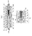
- Figure 2 shows a preferred way for implementing the present invention according to the diagram of Figure 1 .
- Slide 7B can be actuated to the right from V1B for performing the connection 10>11B by opening the flow rate adjusting recesses 27B, 12B > 13B, by opening the overlapping 34, 14B>15, by opening the recess 36; therefore can be driven to the left of the V2B for performing the connection 10>11B by opening the flow rate adjusting recesses 23B, 12B > 14B, by opening the overlapping 35, 13B > 15 by opening the recess 36.
- connection 20 formed by the radial passages 40 which supply oil to the shutter 21, from the radial holes 42 discharging the oil from the shutter 21, from the axial hole 41 connecting to each other the radial holes 40 and 42.
- the radial holes 40 are always connected to channel 10, while radial holes 42 are overlapped in a central position and open to channel 12B and therefore to the corresponding utilisation 13B when the slide 7B is driven by the V1B side.
- Shutter 21 is seated in hole 43 with the spring 22 by which the shutter is kept in a closed position; when the shutter 21 is opened, it abuts the pin 32.
- the pressure at 41 and therefore at 10 acts on the shutter 21 when is opened, when the shutter is closed there is the pressure at 42 which is equal to the one at 12B, when the slide is driven by V1B, plus the spring 22 force.
Landscapes
- Engineering & Computer Science (AREA)
- Physics & Mathematics (AREA)
- Fluid Mechanics (AREA)
- Mechanical Engineering (AREA)
- General Engineering & Computer Science (AREA)
- Fluid-Pressure Circuits (AREA)
- Variable-Direction Aerials And Aerial Arrays (AREA)
- Forklifts And Lifting Vehicles (AREA)
Applications Claiming Priority (1)
| Application Number | Priority Date | Filing Date | Title |
|---|---|---|---|
| IT000039A ITPR20110039A1 (it) | 2011-05-13 | 2011-05-13 | Distributore idraulico con collegamento in parallelo alle nicchie di regolazione della portata del cursore e al compensatore locale |
Publications (2)
| Publication Number | Publication Date |
|---|---|
| EP2522860A1 EP2522860A1 (en) | 2012-11-14 |
| EP2522860B1 true EP2522860B1 (en) | 2014-10-15 |
Family
ID=44554526
Family Applications (1)
| Application Number | Title | Priority Date | Filing Date |
|---|---|---|---|
| EP20120167550 Not-in-force EP2522860B1 (en) | 2011-05-13 | 2012-05-10 | Hydraulic distributor having a connection parallel to the recesses adjusting the flow rate of the slide and to the local compensator |
Country Status (2)
| Country | Link |
|---|---|
| EP (1) | EP2522860B1 (it) |
| IT (1) | ITPR20110039A1 (it) |
Family Cites Families (6)
| Publication number | Priority date | Publication date | Assignee | Title |
|---|---|---|---|---|
| DE69319400T2 (de) * | 1992-04-20 | 1998-12-03 | Hitachi Construction Machinery Co., Ltd., Tokio/Tokyo | Hydraulische schaltungsanordnung für erdbewegungsmaschinen |
| US5937645A (en) * | 1996-01-08 | 1999-08-17 | Nachi-Fujikoshi Corp. | Hydraulic device |
| US7182097B2 (en) | 2004-08-17 | 2007-02-27 | Walvoil S.P.A. | Anti-saturation directional control valve composed of two or more sections with pressure selector compensators |
| US7854115B2 (en) * | 2008-04-25 | 2010-12-21 | Husco International, Inc. | Post-pressure compensated hydraulic control valve with load sense pressure limiting |
| US20100111695A1 (en) | 2008-11-05 | 2010-05-06 | General Electric Company | Apparatus and method for detecting solid water build-up |
| IT1391608B1 (it) | 2008-11-06 | 2012-01-11 | Walvoil Spa | Metodo per limitare la potenza massima richiesta dall impianto idraulico di una macchina per movimento terra e distributore operante detto metodo |
-
2011
- 2011-05-13 IT IT000039A patent/ITPR20110039A1/it unknown
-
2012
- 2012-05-10 EP EP20120167550 patent/EP2522860B1/en not_active Not-in-force
Also Published As
| Publication number | Publication date |
|---|---|
| EP2522860A1 (en) | 2012-11-14 |
| ITPR20110039A1 (it) | 2012-11-14 |
Similar Documents
| Publication | Publication Date | Title |
|---|---|---|
| US9027589B2 (en) | Hydraulic valve with pressure limiter | |
| US8869509B2 (en) | Accessory flow recovery system and method for thermal efficient pump and control system | |
| EP2609312B1 (en) | Integral plus proportional dual pump switching system | |
| CN103649554B (zh) | 基于优先权将流体从多个泵分配至多个液压功能的系统 | |
| JP5290315B2 (ja) | 弁アッセンブリ | |
| US20140069091A1 (en) | Electro-hydraulic system for controlling multiple functions | |
| US7987764B2 (en) | Flow control apparatus for heavy construction equipment | |
| EP1715161B1 (en) | Fuel system | |
| EP0952358A2 (en) | Hose rupture control valve unit | |
| EP1008754B1 (en) | Positive displacement pump systems | |
| US7182097B2 (en) | Anti-saturation directional control valve composed of two or more sections with pressure selector compensators | |
| CN102878126B (zh) | 静液压驱动系统 | |
| CN102562694B (zh) | 负荷传感调节式静液压驱动系统 | |
| JPH07509046A (ja) | 少なくとも1つの液圧式消費機のための制御装置 | |
| EP2951442B1 (en) | Directional control valve with bypass for increased flow rate under reduced pressure conditions | |
| EP3346141B1 (en) | Dual positive displacement pump pressure regulating control and method | |
| CN106640817B (zh) | 适用于双泵合分流液压系统的压力补偿型节能控制阀 | |
| US20060142107A1 (en) | Hydraulic control apparatus | |
| EP2522860A1 (en) | Hydraulic distributor having a connection parallel to the recesses adjusting the flow rate of the slide and to the local compensator | |
| US9752597B2 (en) | Metered fluid source connection to downstream functions in PCLS systems | |
| US9695843B2 (en) | Hydraulic load-sensing control arrangement | |
| EP4080063B1 (en) | Hydraulic distributor with pressure compensator for directional valves | |
| GB2533034A (en) | Systems and methods for flow summation in a hydraulic system with open center control valves | |
| JP2002276608A (ja) | 油圧制御装置 | |
| JP2004239378A (ja) | 油圧制御装置 |
Legal Events
| Date | Code | Title | Description |
|---|---|---|---|
| PUAI | Public reference made under article 153(3) epc to a published international application that has entered the european phase |
Free format text: ORIGINAL CODE: 0009012 |
|
| AK | Designated contracting states |
Kind code of ref document: A1 Designated state(s): AL AT BE BG CH CY CZ DE DK EE ES FI FR GB GR HR HU IE IS IT LI LT LU LV MC MK MT NL NO PL PT RO RS SE SI SK SM TR |
|
| AX | Request for extension of the european patent |
Extension state: BA ME |
|
| 17P | Request for examination filed |
Effective date: 20130417 |
|
| GRAP | Despatch of communication of intention to grant a patent |
Free format text: ORIGINAL CODE: EPIDOSNIGR1 |
|
| INTG | Intention to grant announced |
Effective date: 20140324 |
|
| GRAS | Grant fee paid |
Free format text: ORIGINAL CODE: EPIDOSNIGR3 |
|
| GRAA | (expected) grant |
Free format text: ORIGINAL CODE: 0009210 |
|
| AK | Designated contracting states |
Kind code of ref document: B1 Designated state(s): AL AT BE BG CH CY CZ DE DK EE ES FI FR GB GR HR HU IE IS IT LI LT LU LV MC MK MT NL NO PL PT RO RS SE SI SK SM TR |
|
| REG | Reference to a national code |
Ref country code: GB Ref legal event code: FG4D Ref country code: CH Ref legal event code: EP |
|
| REG | Reference to a national code |
Ref country code: IE Ref legal event code: FG4D |
|
| REG | Reference to a national code |
Ref country code: AT Ref legal event code: REF Ref document number: 691820 Country of ref document: AT Kind code of ref document: T Effective date: 20141115 |
|
| REG | Reference to a national code |
Ref country code: DE Ref legal event code: R096 Ref document number: 602012003390 Country of ref document: DE Effective date: 20141127 |
|
| REG | Reference to a national code |
Ref country code: NL Ref legal event code: VDEP Effective date: 20141015 |
|
| REG | Reference to a national code |
Ref country code: AT Ref legal event code: MK05 Ref document number: 691820 Country of ref document: AT Kind code of ref document: T Effective date: 20141015 |
|
| REG | Reference to a national code |
Ref country code: LT Ref legal event code: MG4D |
|
| PG25 | Lapsed in a contracting state [announced via postgrant information from national office to epo] |
Ref country code: NL Free format text: LAPSE BECAUSE OF FAILURE TO SUBMIT A TRANSLATION OF THE DESCRIPTION OR TO PAY THE FEE WITHIN THE PRESCRIBED TIME-LIMIT Effective date: 20141015 |
|
| PG25 | Lapsed in a contracting state [announced via postgrant information from national office to epo] |
Ref country code: NO Free format text: LAPSE BECAUSE OF FAILURE TO SUBMIT A TRANSLATION OF THE DESCRIPTION OR TO PAY THE FEE WITHIN THE PRESCRIBED TIME-LIMIT Effective date: 20150115 Ref country code: IS Free format text: LAPSE BECAUSE OF FAILURE TO SUBMIT A TRANSLATION OF THE DESCRIPTION OR TO PAY THE FEE WITHIN THE PRESCRIBED TIME-LIMIT Effective date: 20150215 Ref country code: LT Free format text: LAPSE BECAUSE OF FAILURE TO SUBMIT A TRANSLATION OF THE DESCRIPTION OR TO PAY THE FEE WITHIN THE PRESCRIBED TIME-LIMIT Effective date: 20141015 Ref country code: PT Free format text: LAPSE BECAUSE OF FAILURE TO SUBMIT A TRANSLATION OF THE DESCRIPTION OR TO PAY THE FEE WITHIN THE PRESCRIBED TIME-LIMIT Effective date: 20150216 Ref country code: ES Free format text: LAPSE BECAUSE OF FAILURE TO SUBMIT A TRANSLATION OF THE DESCRIPTION OR TO PAY THE FEE WITHIN THE PRESCRIBED TIME-LIMIT Effective date: 20141015 Ref country code: FI Free format text: LAPSE BECAUSE OF FAILURE TO SUBMIT A TRANSLATION OF THE DESCRIPTION OR TO PAY THE FEE WITHIN THE PRESCRIBED TIME-LIMIT Effective date: 20141015 |
|
| PG25 | Lapsed in a contracting state [announced via postgrant information from national office to epo] |
Ref country code: SE Free format text: LAPSE BECAUSE OF FAILURE TO SUBMIT A TRANSLATION OF THE DESCRIPTION OR TO PAY THE FEE WITHIN THE PRESCRIBED TIME-LIMIT Effective date: 20141015 Ref country code: LV Free format text: LAPSE BECAUSE OF FAILURE TO SUBMIT A TRANSLATION OF THE DESCRIPTION OR TO PAY THE FEE WITHIN THE PRESCRIBED TIME-LIMIT Effective date: 20141015 Ref country code: RS Free format text: LAPSE BECAUSE OF FAILURE TO SUBMIT A TRANSLATION OF THE DESCRIPTION OR TO PAY THE FEE WITHIN THE PRESCRIBED TIME-LIMIT Effective date: 20141015 Ref country code: HR Free format text: LAPSE BECAUSE OF FAILURE TO SUBMIT A TRANSLATION OF THE DESCRIPTION OR TO PAY THE FEE WITHIN THE PRESCRIBED TIME-LIMIT Effective date: 20141015 Ref country code: PL Free format text: LAPSE BECAUSE OF FAILURE TO SUBMIT A TRANSLATION OF THE DESCRIPTION OR TO PAY THE FEE WITHIN THE PRESCRIBED TIME-LIMIT Effective date: 20141015 Ref country code: AT Free format text: LAPSE BECAUSE OF FAILURE TO SUBMIT A TRANSLATION OF THE DESCRIPTION OR TO PAY THE FEE WITHIN THE PRESCRIBED TIME-LIMIT Effective date: 20141015 Ref country code: GR Free format text: LAPSE BECAUSE OF FAILURE TO SUBMIT A TRANSLATION OF THE DESCRIPTION OR TO PAY THE FEE WITHIN THE PRESCRIBED TIME-LIMIT Effective date: 20150116 Ref country code: CY Free format text: LAPSE BECAUSE OF FAILURE TO SUBMIT A TRANSLATION OF THE DESCRIPTION OR TO PAY THE FEE WITHIN THE PRESCRIBED TIME-LIMIT Effective date: 20141015 |
|
| REG | Reference to a national code |
Ref country code: DE Ref legal event code: R097 Ref document number: 602012003390 Country of ref document: DE |
|
| PG25 | Lapsed in a contracting state [announced via postgrant information from national office to epo] |
Ref country code: SK Free format text: LAPSE BECAUSE OF FAILURE TO SUBMIT A TRANSLATION OF THE DESCRIPTION OR TO PAY THE FEE WITHIN THE PRESCRIBED TIME-LIMIT Effective date: 20141015 Ref country code: RO Free format text: LAPSE BECAUSE OF FAILURE TO SUBMIT A TRANSLATION OF THE DESCRIPTION OR TO PAY THE FEE WITHIN THE PRESCRIBED TIME-LIMIT Effective date: 20141015 Ref country code: DK Free format text: LAPSE BECAUSE OF FAILURE TO SUBMIT A TRANSLATION OF THE DESCRIPTION OR TO PAY THE FEE WITHIN THE PRESCRIBED TIME-LIMIT Effective date: 20141015 Ref country code: CZ Free format text: LAPSE BECAUSE OF FAILURE TO SUBMIT A TRANSLATION OF THE DESCRIPTION OR TO PAY THE FEE WITHIN THE PRESCRIBED TIME-LIMIT Effective date: 20141015 Ref country code: EE Free format text: LAPSE BECAUSE OF FAILURE TO SUBMIT A TRANSLATION OF THE DESCRIPTION OR TO PAY THE FEE WITHIN THE PRESCRIBED TIME-LIMIT Effective date: 20141015 |
|
| PLBE | No opposition filed within time limit |
Free format text: ORIGINAL CODE: 0009261 |
|
| STAA | Information on the status of an ep patent application or granted ep patent |
Free format text: STATUS: NO OPPOSITION FILED WITHIN TIME LIMIT |
|
| 26N | No opposition filed |
Effective date: 20150716 |
|
| REG | Reference to a national code |
Ref country code: CH Ref legal event code: PL |
|
| PG25 | Lapsed in a contracting state [announced via postgrant information from national office to epo] |
Ref country code: MC Free format text: LAPSE BECAUSE OF FAILURE TO SUBMIT A TRANSLATION OF THE DESCRIPTION OR TO PAY THE FEE WITHIN THE PRESCRIBED TIME-LIMIT Effective date: 20141015 Ref country code: CH Free format text: LAPSE BECAUSE OF NON-PAYMENT OF DUE FEES Effective date: 20150531 Ref country code: LU Free format text: LAPSE BECAUSE OF FAILURE TO SUBMIT A TRANSLATION OF THE DESCRIPTION OR TO PAY THE FEE WITHIN THE PRESCRIBED TIME-LIMIT Effective date: 20150510 Ref country code: LI Free format text: LAPSE BECAUSE OF NON-PAYMENT OF DUE FEES Effective date: 20150531 |
|
| REG | Reference to a national code |
Ref country code: IE Ref legal event code: MM4A |
|
| PG25 | Lapsed in a contracting state [announced via postgrant information from national office to epo] |
Ref country code: SI Free format text: LAPSE BECAUSE OF FAILURE TO SUBMIT A TRANSLATION OF THE DESCRIPTION OR TO PAY THE FEE WITHIN THE PRESCRIBED TIME-LIMIT Effective date: 20141015 |
|
| PG25 | Lapsed in a contracting state [announced via postgrant information from national office to epo] |
Ref country code: IE Free format text: LAPSE BECAUSE OF NON-PAYMENT OF DUE FEES Effective date: 20150510 |
|
| REG | Reference to a national code |
Ref country code: FR Ref legal event code: PLFP Year of fee payment: 5 |
|
| PG25 | Lapsed in a contracting state [announced via postgrant information from national office to epo] |
Ref country code: MT Free format text: LAPSE BECAUSE OF FAILURE TO SUBMIT A TRANSLATION OF THE DESCRIPTION OR TO PAY THE FEE WITHIN THE PRESCRIBED TIME-LIMIT Effective date: 20141015 |
|
| GBPC | Gb: european patent ceased through non-payment of renewal fee |
Effective date: 20160510 |
|
| REG | Reference to a national code |
Ref country code: FR Ref legal event code: PLFP Year of fee payment: 6 |
|
| PG25 | Lapsed in a contracting state [announced via postgrant information from national office to epo] |
Ref country code: HU Free format text: LAPSE BECAUSE OF FAILURE TO SUBMIT A TRANSLATION OF THE DESCRIPTION OR TO PAY THE FEE WITHIN THE PRESCRIBED TIME-LIMIT; INVALID AB INITIO Effective date: 20120510 Ref country code: BG Free format text: LAPSE BECAUSE OF FAILURE TO SUBMIT A TRANSLATION OF THE DESCRIPTION OR TO PAY THE FEE WITHIN THE PRESCRIBED TIME-LIMIT Effective date: 20141015 Ref country code: SM Free format text: LAPSE BECAUSE OF FAILURE TO SUBMIT A TRANSLATION OF THE DESCRIPTION OR TO PAY THE FEE WITHIN THE PRESCRIBED TIME-LIMIT Effective date: 20141015 Ref country code: GB Free format text: LAPSE BECAUSE OF NON-PAYMENT OF DUE FEES Effective date: 20160510 |
|
| PG25 | Lapsed in a contracting state [announced via postgrant information from national office to epo] |
Ref country code: TR Free format text: LAPSE BECAUSE OF FAILURE TO SUBMIT A TRANSLATION OF THE DESCRIPTION OR TO PAY THE FEE WITHIN THE PRESCRIBED TIME-LIMIT Effective date: 20141015 |
|
| PG25 | Lapsed in a contracting state [announced via postgrant information from national office to epo] |
Ref country code: BE Free format text: LAPSE BECAUSE OF FAILURE TO SUBMIT A TRANSLATION OF THE DESCRIPTION OR TO PAY THE FEE WITHIN THE PRESCRIBED TIME-LIMIT Effective date: 20141015 |
|
| REG | Reference to a national code |
Ref country code: FR Ref legal event code: PLFP Year of fee payment: 7 |
|
| PG25 | Lapsed in a contracting state [announced via postgrant information from national office to epo] |
Ref country code: MK Free format text: LAPSE BECAUSE OF FAILURE TO SUBMIT A TRANSLATION OF THE DESCRIPTION OR TO PAY THE FEE WITHIN THE PRESCRIBED TIME-LIMIT Effective date: 20141015 |
|
| PG25 | Lapsed in a contracting state [announced via postgrant information from national office to epo] |
Ref country code: AL Free format text: LAPSE BECAUSE OF FAILURE TO SUBMIT A TRANSLATION OF THE DESCRIPTION OR TO PAY THE FEE WITHIN THE PRESCRIBED TIME-LIMIT Effective date: 20141015 |
|
| PGFP | Annual fee paid to national office [announced via postgrant information from national office to epo] |
Ref country code: IT Payment date: 20230531 Year of fee payment: 12 Ref country code: FR Payment date: 20230526 Year of fee payment: 12 Ref country code: DE Payment date: 20230519 Year of fee payment: 12 |
|
| REG | Reference to a national code |
Ref country code: DE Ref legal event code: R119 Ref document number: 602012003390 Country of ref document: DE |
|
| PG25 | Lapsed in a contracting state [announced via postgrant information from national office to epo] |
Ref country code: DE Free format text: LAPSE BECAUSE OF NON-PAYMENT OF DUE FEES Effective date: 20241203 |
|
| PG25 | Lapsed in a contracting state [announced via postgrant information from national office to epo] |
Ref country code: FR Free format text: LAPSE BECAUSE OF NON-PAYMENT OF DUE FEES Effective date: 20240531 |
|
| PG25 | Lapsed in a contracting state [announced via postgrant information from national office to epo] |
Ref country code: IT Free format text: LAPSE BECAUSE OF NON-PAYMENT OF DUE FEES Effective date: 20240510 |