EP2522877A2 - Dispositif d'isolation des oscillations - Google Patents
Dispositif d'isolation des oscillations Download PDFInfo
- Publication number
- EP2522877A2 EP2522877A2 EP12165470A EP12165470A EP2522877A2 EP 2522877 A2 EP2522877 A2 EP 2522877A2 EP 12165470 A EP12165470 A EP 12165470A EP 12165470 A EP12165470 A EP 12165470A EP 2522877 A2 EP2522877 A2 EP 2522877A2
- Authority
- EP
- European Patent Office
- Prior art keywords
- vibration isolation
- isolation device
- inclined surfaces
- vibration
- concrete foundation
- Prior art date
- Legal status (The legal status is an assumption and is not a legal conclusion. Google has not performed a legal analysis and makes no representation as to the accuracy of the status listed.)
- Granted
Links
Images




Classifications
-
- F—MECHANICAL ENGINEERING; LIGHTING; HEATING; WEAPONS; BLASTING
- F16—ENGINEERING ELEMENTS AND UNITS; GENERAL MEASURES FOR PRODUCING AND MAINTAINING EFFECTIVE FUNCTIONING OF MACHINES OR INSTALLATIONS; THERMAL INSULATION IN GENERAL
- F16F—SPRINGS; SHOCK-ABSORBERS; MEANS FOR DAMPING VIBRATION
- F16F1/00—Springs
- F16F1/36—Springs made of rubber or other material having high internal friction, e.g. thermoplastic elastomers
- F16F1/42—Springs made of rubber or other material having high internal friction, e.g. thermoplastic elastomers characterised by the mode of stressing
- F16F1/52—Springs made of rubber or other material having high internal friction, e.g. thermoplastic elastomers characterised by the mode of stressing loaded in combined stresses
- F16F1/54—Springs made of rubber or other material having high internal friction, e.g. thermoplastic elastomers characterised by the mode of stressing loaded in combined stresses loaded in compression and shear
-
- F—MECHANICAL ENGINEERING; LIGHTING; HEATING; WEAPONS; BLASTING
- F16—ENGINEERING ELEMENTS AND UNITS; GENERAL MEASURES FOR PRODUCING AND MAINTAINING EFFECTIVE FUNCTIONING OF MACHINES OR INSTALLATIONS; THERMAL INSULATION IN GENERAL
- F16M—FRAMES, CASINGS OR BEDS OF ENGINES, MACHINES OR APPARATUS, NOT SPECIFIC TO ENGINES, MACHINES OR APPARATUS PROVIDED FOR ELSEWHERE; STANDS; SUPPORTS
- F16M7/00—Details of attaching or adjusting engine beds, frames, or supporting-legs on foundation or base; Attaching non-moving engine parts, e.g. cylinder blocks
-
- F—MECHANICAL ENGINEERING; LIGHTING; HEATING; WEAPONS; BLASTING
- F16—ENGINEERING ELEMENTS AND UNITS; GENERAL MEASURES FOR PRODUCING AND MAINTAINING EFFECTIVE FUNCTIONING OF MACHINES OR INSTALLATIONS; THERMAL INSULATION IN GENERAL
- F16M—FRAMES, CASINGS OR BEDS OF ENGINES, MACHINES OR APPARATUS, NOT SPECIFIC TO ENGINES, MACHINES OR APPARATUS PROVIDED FOR ELSEWHERE; STANDS; SUPPORTS
- F16M9/00—Special layout of foundations with respect to machinery to be supported
Definitions
- the invention relates to a vibration isolation device for vibration-damped receiving a mass with at least one insulation unit, which carries on at least two inclined surfaces of at least one inclined bearing arranged elastic and damping insulating.
- a vibration isolation device of this kind is in the DE 102 33 804 B3 specified.
- a bearing block unit with cuboidal or cube-shaped outer contour is received on a base support, which is composed of four sub-blocks and in its interior has an upwardly opening truncated pyramidal receptacle with oblique support surfaces.
- base support which is composed of four sub-blocks and in its interior has an upwardly opening truncated pyramidal receptacle with oblique support surfaces.
- plate-shaped elastic and damping insulating elements are arranged in the form of elastomeric bodies on which a support for receiving a vibration-isolated to be stored object is supported.
- the DE 42 13 656 C2 shows a vibration-damping assembly composite plate with an intermediate layer of polymer for vibration decoupling of machine parts or machines with each other or machines or machine parts against a foundation.
- Vibration isolators of the aforementioned type are used to establish such large, heavy machines vibration isolation, with the necessary elastic and damping elements (spring-damper systems), usually between the press, machine or plant feet and the concrete foundations are arranged.
- spring-damper systems usually between the press, machine or plant feet and the concrete foundations are arranged.
- low natural frequencies of the vibration isolation elements are desirable, which physically require relatively large spring travel, which can build up the vibration isolation elements high.
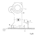
- an unfavorable height may result (cf. Fig. 1 B) , which are compensated by additional constructive measures, such as pedestals or elaborate and expensive steel structures. Frequently retrofitting such machines with vibration-isolating elements fails from such considerations.
- hitherto isolation devices are highly constructive and very large, especially for large objects to be insulated, they also require considerable effort in the production, since they are usually made of steel and are very heavy and machined solid material in these dimensions only on special machines can be.
- the present invention has for its object to provide a vibration isolation device of the type mentioned above, the better constructive voting options results in self-standing vibration isolation tasks.
- the angular contact bearings are formed in a concrete foundation, wherein the inclined surfaces are formed by molding surfaces of the concrete foundation.
- the vibration isolation device is advantageously integrated into the local environment of the mass or object to be insulated, wherein the already be prepared and adapted to the requirements concrete foundation with the provisions for the vibration isolation device can be planned and executed, the vibration damping insulation with the concrete foundation can be connected or fixed to them so that they can be placed at suitable locations and in coordinated sizes between the foundation and the vibration isolated object to be arranged such.
- the vibration damping insulation with the concrete foundation can be connected or fixed to them so that they can be placed at suitable locations and in coordinated sizes between the foundation and the vibration isolated object to be arranged such.
- As machine or building can be integrated.
- the measures are advantageous in that the oblique surfaces of a respective angular contact bearing are arranged in the manner of mutually inclined side surfaces of a triangular or trapezoidal prism, which is aligned horizontally with respect to the absolute vertical direction in the direction of gravity, wherein the two inclined surfaces down or are directed upward to each other.
- the inclined surfaces are formed by at least portions of lateral boundary surfaces of the recesses or that they are formed at upwardly directed portions of the concrete foundation, in particular within the recess.
- the pressure is uniformly and over a large area in the concrete by means of the metal plates, preferably steel plates distributed and occurring in the deformation of the insulating, especially elastomers, shear stresses due to transverse strains are absorbed in the plane or not as much hindered as in a pure concrete surface, so that cracking in the foundation is additionally prevented.
- the insulating elements of an angular bearing are coupled to one another via a pressure unit, the individual elastomer springs can not deform as freely under load as they do during individual loading, so that advantages of the mode of operation result from the resulting bridge connection via the pressure unit.
- the assembly and the function are also favored by the fact that the printing unit is provided on its upper side with a flat horizontal bearing surface.
- the printing unit is designed as a pressure piece made of metal or concrete and that in training concrete on its upper side, a metal plate is anchored.
- a further advantageous embodiment with favorable construction options is that a plurality of angular contact bearings are coupled to one another via a receiving plate to an angular contact bearing assembly.
- the function and structure are also favored by the fact that the inclination angle of the inclined surfaces in a vertical transverse plane with respect to the horizontal (and thus verticals) are the same size.
- the measures contribute to a high degree of stability, particularly in the area of inclined surfaces, where the concrete foundation is made of shrink-free concrete.
- Advantages in the construction of the vibration isolation device also result from the fact that the insulating elements are designed as plate-like elastomer body lying parallel to the associated inclined surface top and bottom. This also offers advantageous adaptation options to different requirements.
- Advantageous voting options also result from the fact that the elastomeric bodies have different layers of elastomeric material with different vibration / damping properties.
- Fig. 1A shows a z. B. on the ground foundation of a factory-built machine 20, namely a forging press, which is mounted on a vibration isolation device 1 against the existing concrete foundation 11 vibration isolation.
- the vibration isolation device 1 has a plurality of vibration isolation units 10, two of which can be seen in cross-section and one enlarged in perspective view.
- the insulation units 10 are arranged in a recess 5 of the concrete foundation 11, whose lateral boundary planes form inclined surfaces 40 of an angular bearing 4, such as Fig. 2 more clearly shows.
- the vibration isolation is formed by elastic and damping insulating elements 100 made of elastomeric material, which are arranged on the inclined surfaces 40 of the angular bearing 4 and against which the mass to be insulated 2 forming machine 20 is supported via a two insulating elements 100 bridging pressure piece 102.
- the underside of the machine 20 is compared to the top of the foundation, which forms the floor or the floor plane (floor), only slightly optionally on existing feet or only about the slightly protruding with its top pressure piece 102 spaced so far that oscillations to maximum vibration amplitudes can still take place unhindered.
- the underfloor arrangement of the inclined surfaces 40 the operating components of the machine 20 are fully perceptible or actuable by an operator 3, who likewise stands on the use plane or ground plane 0.
- the elastic and damping insulating members 100 function as members with vibration and damping characteristics, wherein the spring-damper systems formed by the elastic and damping elements between the machine feet and the concrete foundation provide good shock and vibration isolation in that 100 deep natural frequencies are caused with the insulating elements, which can be associated with relatively large spring travel.
- these do not affect due to the recessed installation of the insulation unit 10 in an unfavorable displacement of the controls, as would be the case with structures on the Nutz- or ground plane 0 and in Fig. 1B is shown, in which a conventional vibration isolation device 90 is shown.
- the constructive vibration isolation device 90 results in conventional design an unfavorable height displacement of the operating device by a height h1.
- the isolation units 10 with the inclined bearings 4 are present, as the enlarged perspective view in Fig. 1A shows, designed in the manner of a horizontal triangular prism, wherein the inclined surfaces 40 are inclined downward to each other.
- the inclined surfaces 40 of the angular contact bearings 4 could also be further pulled apart in cross-section approximately corresponding to a trapezoidal prism.
- the cavity between the arranged on the inclined surfaces 40 insulating 100 of an angular bearing 4 is filled with the pressure pad 102 to form a support unit 12 under the respective contact area, in particular machine base.
- Fig. 2 further shows 11 metal plates, preferably plane-parallel steel plates 101 are applied to the inclined surfaces 40 of the concrete foundation and in the concrete foundation 11 fixed by means of anchoring elements 30.
- advantageously shrinkage-free concrete can be used to increase the stability of the angular bearing 4 and to avoid a gearing of the concrete and cracking.
- the steel plates are embedded in the production of the angular bearing 4. They distribute the pressure uniformly and over a large area in the concrete and absorb shear stresses occurring during the deformation of the insulating elements 100, especially of elastomers, due to transverse strains in the plane, whereby the transverse strains are not hindered as much as is the case with a pure concrete surface. so that the metal plates 101 contribute to the prevention of cracking in the concrete foundation 11.
- the solid pressure piece 102 may also be made of concrete, advantageously with the least possible shrinkage.
- the pressure piece 102 On its flat, horizontal surface, the pressure piece 102 carries a plane-parallel receiving plate 103, preferably also made of metal, in particular steel, which is fastened by means of further anchoring elements 30 in the pressure piece 102.
- the entire pressure piece 102 may be made of metal, especially if its volume is relatively small, as it is, for. B. in isolation units 10 for smaller machines 20 may be the case.
- the pressure piece results in a firm connection between the insulating elements 100.
- the type of oblique arrangement of the elastic and damping insulating members 100 and the elastomeric spring formed thereby is an advantageous embodiment, a system or the mass to be stored 2, to decouple the horizontal axes. If the distances between the springs formed by the insulating elements 100 are properly taken into account to the focal plane, in this way the moment action of the spring restoring forces can be influenced by the angular position of the elastomer springs, that the resulting main elastic plane in the horizontal Priority level is effective, such as Fig. 3 shows.
- the excitation forces of the elastomer springs in the horizontal direction are denoted by F e , wherein the spring restoring forces in the normal direction of the inclined surfaces 40 and parallel to these or to their inclination direction F R1 , F R2 are registered.
- the vertical axis HA pointing in the direction of the vertical and the transverse axis QA pointing at right angles to this in the transverse direction of the angular bearing 4 are shown.
- the inclined surfaces 40 are arranged symmetrically to a vertical central longitudinal plane of the angular bearing 4, wherein the distances between the vertical center longitudinal plane of the angular bearing 4 and the centers of the insulating 100 with a Q and the distances between the center of gravity of the mass 2 and the center of the insulating body 100 in the direction the vertical axis are denoted by a H. Also entered is an outward force F Nx , which is significant here because it is related to the inevitable guidance of the springs. The inevitable leadership of the springs is a consequence of the outward force F Nx , which arises due to the firm connection between the two diagonal springs.
- an angular bearing 4 Another advantage of an angular bearing 4 is that the shear stress and compressive stress are "combined" by the inclination of the elastomer springs. Since pressure-loaded elastomer springs in the horizontal direction are usually “softer” by a factor of 2 to 3 than in the vertical direction, this can be used to reduce the vertical natural frequencies f 0z of the elastomer spring and at the same time the horizontal natural frequencies f 0x , f 0y , stabilizing the machine mounted thereon. This mode of action is in principle in Fig. 4 in which a force F z in the normal direction acts on the insulating element 100.
- vibration isolation device such a structure with angular bearing 4 is advantageously integrated into the concrete foundation 11, whereby a high constructive, voluminous, difficult to manufacture and to be handled construction is avoided and the concrete foundation 11 provides a stable base without complex installation and connection measures. A displacement of the bearings in the horizontal direction or rotation is not possible.
- Fig. 5 shows next to the in Fig. 2
- two formed in a concrete foundation 11 inclined surfaces 40 are further pulled apart and take elastic and damping insulating elements 100, in particular of elastomeric material, on.
- the distance between the insulating elements 100 is bridged with a fixed pressure piece in the form of a bridge portion 102 'on the flat horizontal top, a large receiving area for a mass 2, z. B. a machine 20 or z. B. results in a building.
- a bridge portion 102 a large receiving area for a mass 2, z. B. a machine 20 or z. B. results in a building.
- an enlarged composite of insulating units 10 is formed with a plurality of inclined bearings 4, each comprising two inclined surfaces 40 of the structure described above, by two insulating elements 100 of an angular bearing 4, a fixed pressure piece 102 is applied and in turn on two pressure pieces 102 a spanning fixed bridge portion 102 "
- different vibration / damping arrangements can be produced which can be used with differently extended masses 2 and offer favorable adaptation possibilities, whereby a coupled system for vibration isolation can be constructed by means of the bridge parts 102 ', 102 "and pressure pieces 102.
- the inclinations of the inclined surfaces 40 with respect to the horizontal or vertical can be selected with different inclination angle ⁇ , z. B. in a range between 20 ° and 70 °.
- insulating elements can 100 are used with different vibration / damping properties, which can also be composed of several parallel layers with different vibration / damping properties.
- Fig. 6 shows as a further embodiment, the storage of a structure 2 'on a vibration isolation device 1.
- insulation units 10 also formed in a concrete foundation 11 angular contact bearings 4 with inclined surfaces 40.
- the inclined surfaces 40 are in this case obliquely inclined to each other, wherein the pressure piece is formed corresponding hollow on its underside and is fitted with adapted inclined surfaces on the arranged on the inclined surfaces 40 insulating 100.
- the angular contact bearings 4 are arranged with the inclined surfaces 40 in a recess of the concrete foundation 11, which in turn is mounted in a substrate 13.
- a receiving plate 103 which is connected to the pressure pieces 102 by means of anchoring elements extends.
- the pressure pieces 102 may in turn be advantageously made of concrete, while the receiving plate 103 made of metal or concrete, z. B. with steel reinforcement is made.
- the structure may be performed according to the above-described embodiments.
- This type of introduction elastic and damping insulating 100 in conjunction with a building 2 'results in z. As in tall, slender, free-standing buildings advantages in vibration isolation, for example, occurring by wind load horizontally acting forces.
- the vibration isolation device 1 with the insulating elements 100 allows a suitable adaptation to the requirements of the vibration isolation.
Landscapes
- Engineering & Computer Science (AREA)
- General Engineering & Computer Science (AREA)
- Mechanical Engineering (AREA)
- Health & Medical Sciences (AREA)
- Child & Adolescent Psychology (AREA)
- Vibration Prevention Devices (AREA)
- Buildings Adapted To Withstand Abnormal External Influences (AREA)
Applications Claiming Priority (1)
| Application Number | Priority Date | Filing Date | Title |
|---|---|---|---|
| DE102011050355A DE102011050355A1 (de) | 2011-05-13 | 2011-05-13 | Schwingungsisolationseinrichtung |
Publications (3)
| Publication Number | Publication Date |
|---|---|
| EP2522877A2 true EP2522877A2 (fr) | 2012-11-14 |
| EP2522877A3 EP2522877A3 (fr) | 2013-10-23 |
| EP2522877B1 EP2522877B1 (fr) | 2016-07-20 |
Family
ID=46027709
Family Applications (1)
| Application Number | Title | Priority Date | Filing Date |
|---|---|---|---|
| EP12165470.1A Active EP2522877B1 (fr) | 2011-05-13 | 2012-04-25 | Dispositif d'isolation des oscillations |
Country Status (2)
| Country | Link |
|---|---|
| EP (1) | EP2522877B1 (fr) |
| DE (1) | DE102011050355A1 (fr) |
Cited By (3)
| Publication number | Priority date | Publication date | Assignee | Title |
|---|---|---|---|---|
| CN112458800A (zh) * | 2020-11-18 | 2021-03-09 | 成都主导科技有限责任公司 | 复合减震钢轨枕 |
| CN116181795A (zh) * | 2022-12-13 | 2023-05-30 | 中国船舶重工集团公司第七一九研究所 | 多向减振轴承基座结构 |
| CN117365174A (zh) * | 2023-09-26 | 2024-01-09 | 广州大学 | 一种振震双控的斜置式正交组合隔振支座 |
Families Citing this family (2)
| Publication number | Priority date | Publication date | Assignee | Title |
|---|---|---|---|---|
| DE102015106210B4 (de) | 2015-04-22 | 2017-06-29 | Isoloc Schwingungstechnik Gmbh | Schwingungsisolationseinheit |
| DE102018129542B4 (de) | 2018-11-23 | 2022-08-25 | Isoloc Schwingungstechnik Gmbh | Maschinenaufstelleinheit |
Citations (2)
| Publication number | Priority date | Publication date | Assignee | Title |
|---|---|---|---|---|
| DE4213656C2 (fr) | 1992-04-25 | 1994-03-03 | Epucret Polymertechnik Gmbh, 73098 Rechberghausen, De | |
| DE10233804B3 (de) | 2002-07-25 | 2004-02-26 | Isoloc Schwingungstechnik Gmbh | Schwingungsisolator |
Family Cites Families (6)
| Publication number | Priority date | Publication date | Assignee | Title |
|---|---|---|---|---|
| FR1257789A (fr) * | 1960-02-23 | 1961-04-07 | Vibrachoc Sa | Dispositif de montage d'objets et d'appareils évitant la transmission des vibrations |
| GB1148983A (en) * | 1966-07-05 | 1969-04-16 | Maclellan Rubber Ltd | Improvements in or relating to structural bearings |
| CH612610A5 (en) * | 1976-03-23 | 1979-08-15 | Studer Ag Fritz | Machine stand for machine tools |
| DE2828714A1 (de) * | 1978-06-30 | 1980-01-10 | Clouth Gummiwerke Ag | Einrichtung zur schalldaemmenden lagerung schwerer bauteile |
| FR2515718A1 (fr) * | 1981-10-29 | 1983-05-06 | Louis Pierre | Procede de construction d'edifices susceptibles de resister a des seismes et dispositifs pour la mise en oeuvre de ce procede |
| DE19503220A1 (de) * | 1994-02-10 | 1995-08-17 | Butzbacher Weichenbau Gmbh | System für den schotterlosen Oberbau von Gleisanlagen |
-
2011
- 2011-05-13 DE DE102011050355A patent/DE102011050355A1/de not_active Ceased
-
2012
- 2012-04-25 EP EP12165470.1A patent/EP2522877B1/fr active Active
Patent Citations (2)
| Publication number | Priority date | Publication date | Assignee | Title |
|---|---|---|---|---|
| DE4213656C2 (fr) | 1992-04-25 | 1994-03-03 | Epucret Polymertechnik Gmbh, 73098 Rechberghausen, De | |
| DE10233804B3 (de) | 2002-07-25 | 2004-02-26 | Isoloc Schwingungstechnik Gmbh | Schwingungsisolator |
Cited By (4)
| Publication number | Priority date | Publication date | Assignee | Title |
|---|---|---|---|---|
| CN112458800A (zh) * | 2020-11-18 | 2021-03-09 | 成都主导科技有限责任公司 | 复合减震钢轨枕 |
| CN116181795A (zh) * | 2022-12-13 | 2023-05-30 | 中国船舶重工集团公司第七一九研究所 | 多向减振轴承基座结构 |
| CN116181795B (zh) * | 2022-12-13 | 2026-05-12 | 中国船舶重工集团公司第七一九研究所 | 多向减振轴承基座结构 |
| CN117365174A (zh) * | 2023-09-26 | 2024-01-09 | 广州大学 | 一种振震双控的斜置式正交组合隔振支座 |
Also Published As
| Publication number | Publication date |
|---|---|
| EP2522877A3 (fr) | 2013-10-23 |
| DE102011050355A1 (de) | 2012-11-15 |
| EP2522877B1 (fr) | 2016-07-20 |
Similar Documents
| Publication | Publication Date | Title |
|---|---|---|
| EP3597840A1 (fr) | Installation modulaire et set de montage pour une installation modulaire | |
| EP2522877B1 (fr) | Dispositif d'isolation des oscillations | |
| DE202016009246U1 (de) | Turm für eine Windkraftanlage aus ringsegmentförmigen Betonfertigteilen | |
| EP3690159A1 (fr) | Enveloppe de bâtiment et procédé d'isolement thermique des enveloppes de bâtiment en béton | |
| DE10353907B4 (de) | Schwingungsisolationsvorrichtung insbesondere für den Erdbebenschutz von Gebäuden | |
| EP1590579B1 (fr) | Structure de palier pour transmission amortie de forces de choc et/ou de vibration | |
| EP2626509B1 (fr) | Appareillage de coffrage | |
| EP3225758B1 (fr) | Élément de raccordement d'isolement thermique entre un élément de bâtiment vertical et un élément de bâtiment horizontal | |
| DE10145857A1 (de) | Lagerkonstruktion zur gedämpften Übertragung von Stoß- und/oder Schwingungskräften, insbesondere für Bauwerke, welche einer seismischen Belastung ausgesetzt sind | |
| DE102017218641A1 (de) | Schwingungstilger, insbesondere für einen Schaltschrank | |
| EP0056258B1 (fr) | Dispositif d'amortissement d'oscillations et d'absorption d'énergie | |
| DE3342072A1 (de) | Klammer fuer plattenfoermige betonelemente | |
| EP3492665A1 (fr) | Pièce préfabriquée de béton dotée d'au moins un composant recevant la charge ainsi que plaque de raccordement destinée à être agencée dans le joint de raccordement entre une telle pièce préfabriquée de béton et le composant recevant la charge | |
| DE102015106210B4 (de) | Schwingungsisolationseinheit | |
| DE102021122670B4 (de) | Vorrichtung zum Schutz von Gebäuden vor einem Erdbeben | |
| EP3225759B1 (fr) | Élément de raccordement d'isolation thermique d'éléments de bâtiments verticaux reliés | |
| DE102015109887A1 (de) | Wärmedämmsystem zur vertikalen, lastabtragenden Verbindung von aus Beton zu erstellenden Gebäudeteilen | |
| EP3935222B1 (fr) | Fondationj d'un plafond | |
| WO2014173543A2 (fr) | Ouvrage présentant un dispositif d'atténuation d'un tremblement de terre | |
| EP3569786A1 (fr) | Bâtiment avec un dispositif de stockage amortissant des vibrations et procédé d'installation ultérieur du dispositif de stockage amortissement des vibrations | |
| DE10125741A1 (de) | Schwingungsgedämpftes Trägersystem sowie Verfahren zur Schwingungsdämpfung | |
| EP3835501B1 (fr) | Arrangement pour connecter une pièce de construction avec une partie extérieure frontale | |
| CH684940A5 (de) | Lagerung für einen Kugelbehälter und Verfahren zur Herstellung derselben. | |
| EP1544366A1 (fr) | Bâtiment constitué d' éléments de pièces préfabriqués | |
| DE102010056577A1 (de) | Futterplatte |
Legal Events
| Date | Code | Title | Description |
|---|---|---|---|
| PUAI | Public reference made under article 153(3) epc to a published international application that has entered the european phase |
Free format text: ORIGINAL CODE: 0009012 |
|
| AK | Designated contracting states |
Kind code of ref document: A2 Designated state(s): AL AT BE BG CH CY CZ DE DK EE ES FI FR GB GR HR HU IE IS IT LI LT LU LV MC MK MT NL NO PL PT RO RS SE SI SK SM TR |
|
| AX | Request for extension of the european patent |
Extension state: BA ME |
|
| PUAL | Search report despatched |
Free format text: ORIGINAL CODE: 0009013 |
|
| AK | Designated contracting states |
Kind code of ref document: A3 Designated state(s): AL AT BE BG CH CY CZ DE DK EE ES FI FR GB GR HR HU IE IS IT LI LT LU LV MC MK MT NL NO PL PT RO RS SE SI SK SM TR |
|
| AX | Request for extension of the european patent |
Extension state: BA ME |
|
| RIC1 | Information provided on ipc code assigned before grant |
Ipc: F16F 1/54 20060101AFI20130917BHEP |
|
| 17P | Request for examination filed |
Effective date: 20140423 |
|
| RBV | Designated contracting states (corrected) |
Designated state(s): AL AT BE BG CH CY CZ DE DK EE ES FI FR GB GR HR HU IE IS IT LI LT LU LV MC MK MT NL NO PL PT RO RS SE SI SK SM TR |
|
| REG | Reference to a national code |
Ref country code: DE Ref legal event code: R079 Ref document number: 502012007689 Country of ref document: DE Free format text: PREVIOUS MAIN CLASS: F16F0001540000 Ipc: F16M0007000000 |
|
| RIC1 | Information provided on ipc code assigned before grant |
Ipc: F16M 7/00 20060101AFI20151008BHEP Ipc: F16M 9/00 20060101ALI20151008BHEP |
|
| GRAP | Despatch of communication of intention to grant a patent |
Free format text: ORIGINAL CODE: EPIDOSNIGR1 |
|
| INTG | Intention to grant announced |
Effective date: 20160126 |
|
| GRAP | Despatch of communication of intention to grant a patent |
Free format text: ORIGINAL CODE: EPIDOSNIGR1 |
|
| INTG | Intention to grant announced |
Effective date: 20160502 |
|
| GRAS | Grant fee paid |
Free format text: ORIGINAL CODE: EPIDOSNIGR3 |
|
| GRAA | (expected) grant |
Free format text: ORIGINAL CODE: 0009210 |
|
| AK | Designated contracting states |
Kind code of ref document: B1 Designated state(s): AL AT BE BG CH CY CZ DE DK EE ES FI FR GB GR HR HU IE IS IT LI LT LU LV MC MK MT NL NO PL PT RO RS SE SI SK SM TR |
|
| REG | Reference to a national code |
Ref country code: GB Ref legal event code: FG4D Free format text: NOT ENGLISH |
|
| REG | Reference to a national code |
Ref country code: CH Ref legal event code: EP |
|
| REG | Reference to a national code |
Ref country code: IE Ref legal event code: FG4D Free format text: LANGUAGE OF EP DOCUMENT: GERMAN |
|
| REG | Reference to a national code |
Ref country code: AT Ref legal event code: REF Ref document number: 814399 Country of ref document: AT Kind code of ref document: T Effective date: 20160815 |
|
| REG | Reference to a national code |
Ref country code: CH Ref legal event code: NV Representative=s name: SCHNEIDER FELDMANN AG PATENT- UND MARKENANWAEL, CH |
|
| REG | Reference to a national code |
Ref country code: DE Ref legal event code: R096 Ref document number: 502012007689 Country of ref document: DE |
|
| REG | Reference to a national code |
Ref country code: LT Ref legal event code: MG4D |
|
| REG | Reference to a national code |
Ref country code: NL Ref legal event code: MP Effective date: 20160720 |
|
| PG25 | Lapsed in a contracting state [announced via postgrant information from national office to epo] |
Ref country code: IS Free format text: LAPSE BECAUSE OF FAILURE TO SUBMIT A TRANSLATION OF THE DESCRIPTION OR TO PAY THE FEE WITHIN THE PRESCRIBED TIME-LIMIT Effective date: 20161120 Ref country code: RS Free format text: LAPSE BECAUSE OF FAILURE TO SUBMIT A TRANSLATION OF THE DESCRIPTION OR TO PAY THE FEE WITHIN THE PRESCRIBED TIME-LIMIT Effective date: 20160720 Ref country code: NL Free format text: LAPSE BECAUSE OF FAILURE TO SUBMIT A TRANSLATION OF THE DESCRIPTION OR TO PAY THE FEE WITHIN THE PRESCRIBED TIME-LIMIT Effective date: 20160720 Ref country code: LT Free format text: LAPSE BECAUSE OF FAILURE TO SUBMIT A TRANSLATION OF THE DESCRIPTION OR TO PAY THE FEE WITHIN THE PRESCRIBED TIME-LIMIT Effective date: 20160720 Ref country code: HR Free format text: LAPSE BECAUSE OF FAILURE TO SUBMIT A TRANSLATION OF THE DESCRIPTION OR TO PAY THE FEE WITHIN THE PRESCRIBED TIME-LIMIT Effective date: 20160720 Ref country code: FI Free format text: LAPSE BECAUSE OF FAILURE TO SUBMIT A TRANSLATION OF THE DESCRIPTION OR TO PAY THE FEE WITHIN THE PRESCRIBED TIME-LIMIT Effective date: 20160720 Ref country code: IT Free format text: LAPSE BECAUSE OF FAILURE TO SUBMIT A TRANSLATION OF THE DESCRIPTION OR TO PAY THE FEE WITHIN THE PRESCRIBED TIME-LIMIT Effective date: 20160720 Ref country code: NO Free format text: LAPSE BECAUSE OF FAILURE TO SUBMIT A TRANSLATION OF THE DESCRIPTION OR TO PAY THE FEE WITHIN THE PRESCRIBED TIME-LIMIT Effective date: 20161020 |
|
| PG25 | Lapsed in a contracting state [announced via postgrant information from national office to epo] |
Ref country code: PT Free format text: LAPSE BECAUSE OF FAILURE TO SUBMIT A TRANSLATION OF THE DESCRIPTION OR TO PAY THE FEE WITHIN THE PRESCRIBED TIME-LIMIT Effective date: 20161121 Ref country code: ES Free format text: LAPSE BECAUSE OF FAILURE TO SUBMIT A TRANSLATION OF THE DESCRIPTION OR TO PAY THE FEE WITHIN THE PRESCRIBED TIME-LIMIT Effective date: 20160720 Ref country code: PL Free format text: LAPSE BECAUSE OF FAILURE TO SUBMIT A TRANSLATION OF THE DESCRIPTION OR TO PAY THE FEE WITHIN THE PRESCRIBED TIME-LIMIT Effective date: 20160720 Ref country code: LV Free format text: LAPSE BECAUSE OF FAILURE TO SUBMIT A TRANSLATION OF THE DESCRIPTION OR TO PAY THE FEE WITHIN THE PRESCRIBED TIME-LIMIT Effective date: 20160720 Ref country code: GR Free format text: LAPSE BECAUSE OF FAILURE TO SUBMIT A TRANSLATION OF THE DESCRIPTION OR TO PAY THE FEE WITHIN THE PRESCRIBED TIME-LIMIT Effective date: 20161021 Ref country code: SE Free format text: LAPSE BECAUSE OF FAILURE TO SUBMIT A TRANSLATION OF THE DESCRIPTION OR TO PAY THE FEE WITHIN THE PRESCRIBED TIME-LIMIT Effective date: 20160720 |
|
| REG | Reference to a national code |
Ref country code: DE Ref legal event code: R097 Ref document number: 502012007689 Country of ref document: DE |
|
| PG25 | Lapsed in a contracting state [announced via postgrant information from national office to epo] |
Ref country code: RO Free format text: LAPSE BECAUSE OF FAILURE TO SUBMIT A TRANSLATION OF THE DESCRIPTION OR TO PAY THE FEE WITHIN THE PRESCRIBED TIME-LIMIT Effective date: 20160720 Ref country code: EE Free format text: LAPSE BECAUSE OF FAILURE TO SUBMIT A TRANSLATION OF THE DESCRIPTION OR TO PAY THE FEE WITHIN THE PRESCRIBED TIME-LIMIT Effective date: 20160720 |
|
| PLBE | No opposition filed within time limit |
Free format text: ORIGINAL CODE: 0009261 |
|
| STAA | Information on the status of an ep patent application or granted ep patent |
Free format text: STATUS: NO OPPOSITION FILED WITHIN TIME LIMIT |
|
| PG25 | Lapsed in a contracting state [announced via postgrant information from national office to epo] |
Ref country code: DK Free format text: LAPSE BECAUSE OF FAILURE TO SUBMIT A TRANSLATION OF THE DESCRIPTION OR TO PAY THE FEE WITHIN THE PRESCRIBED TIME-LIMIT Effective date: 20160720 Ref country code: CZ Free format text: LAPSE BECAUSE OF FAILURE TO SUBMIT A TRANSLATION OF THE DESCRIPTION OR TO PAY THE FEE WITHIN THE PRESCRIBED TIME-LIMIT Effective date: 20160720 Ref country code: SM Free format text: LAPSE BECAUSE OF FAILURE TO SUBMIT A TRANSLATION OF THE DESCRIPTION OR TO PAY THE FEE WITHIN THE PRESCRIBED TIME-LIMIT Effective date: 20160720 Ref country code: BG Free format text: LAPSE BECAUSE OF FAILURE TO SUBMIT A TRANSLATION OF THE DESCRIPTION OR TO PAY THE FEE WITHIN THE PRESCRIBED TIME-LIMIT Effective date: 20161020 Ref country code: SK Free format text: LAPSE BECAUSE OF FAILURE TO SUBMIT A TRANSLATION OF THE DESCRIPTION OR TO PAY THE FEE WITHIN THE PRESCRIBED TIME-LIMIT Effective date: 20160720 |
|
| 26N | No opposition filed |
Effective date: 20170421 |
|
| PG25 | Lapsed in a contracting state [announced via postgrant information from national office to epo] |
Ref country code: SI Free format text: LAPSE BECAUSE OF FAILURE TO SUBMIT A TRANSLATION OF THE DESCRIPTION OR TO PAY THE FEE WITHIN THE PRESCRIBED TIME-LIMIT Effective date: 20160720 |
|
| REG | Reference to a national code |
Ref country code: DE Ref legal event code: R082 Ref document number: 502012007689 Country of ref document: DE Representative=s name: PATENTANWAELTE JECK, FLECK & PARTNER MBB, DE Ref country code: DE Ref legal event code: R082 Ref document number: 502012007689 Country of ref document: DE Representative=s name: JECK - FLECK PATENTANWAELTE, DE |
|
| GBPC | Gb: european patent ceased through non-payment of renewal fee |
Effective date: 20170425 |
|
| REG | Reference to a national code |
Ref country code: IE Ref legal event code: MM4A |
|
| REG | Reference to a national code |
Ref country code: FR Ref legal event code: ST Effective date: 20171229 |
|
| PG25 | Lapsed in a contracting state [announced via postgrant information from national office to epo] |
Ref country code: MC Free format text: LAPSE BECAUSE OF FAILURE TO SUBMIT A TRANSLATION OF THE DESCRIPTION OR TO PAY THE FEE WITHIN THE PRESCRIBED TIME-LIMIT Effective date: 20160720 Ref country code: FR Free format text: LAPSE BECAUSE OF NON-PAYMENT OF DUE FEES Effective date: 20170502 |
|
| PG25 | Lapsed in a contracting state [announced via postgrant information from national office to epo] |
Ref country code: LU Free format text: LAPSE BECAUSE OF NON-PAYMENT OF DUE FEES Effective date: 20170425 Ref country code: GB Free format text: LAPSE BECAUSE OF NON-PAYMENT OF DUE FEES Effective date: 20170425 |
|
| REG | Reference to a national code |
Ref country code: BE Ref legal event code: MM Effective date: 20170430 |
|
| PG25 | Lapsed in a contracting state [announced via postgrant information from national office to epo] |
Ref country code: IE Free format text: LAPSE BECAUSE OF NON-PAYMENT OF DUE FEES Effective date: 20170425 |
|
| PG25 | Lapsed in a contracting state [announced via postgrant information from national office to epo] |
Ref country code: BE Free format text: LAPSE BECAUSE OF NON-PAYMENT OF DUE FEES Effective date: 20170430 |
|
| PG25 | Lapsed in a contracting state [announced via postgrant information from national office to epo] |
Ref country code: MT Free format text: LAPSE BECAUSE OF FAILURE TO SUBMIT A TRANSLATION OF THE DESCRIPTION OR TO PAY THE FEE WITHIN THE PRESCRIBED TIME-LIMIT Effective date: 20160720 |
|
| PG25 | Lapsed in a contracting state [announced via postgrant information from national office to epo] |
Ref country code: AL Free format text: LAPSE BECAUSE OF FAILURE TO SUBMIT A TRANSLATION OF THE DESCRIPTION OR TO PAY THE FEE WITHIN THE PRESCRIBED TIME-LIMIT Effective date: 20160720 |
|
| PG25 | Lapsed in a contracting state [announced via postgrant information from national office to epo] |
Ref country code: HU Free format text: LAPSE BECAUSE OF FAILURE TO SUBMIT A TRANSLATION OF THE DESCRIPTION OR TO PAY THE FEE WITHIN THE PRESCRIBED TIME-LIMIT; INVALID AB INITIO Effective date: 20120425 |
|
| PGFP | Annual fee paid to national office [announced via postgrant information from national office to epo] |
Ref country code: CH Payment date: 20190418 Year of fee payment: 8 |
|
| PG25 | Lapsed in a contracting state [announced via postgrant information from national office to epo] |
Ref country code: CY Free format text: LAPSE BECAUSE OF NON-PAYMENT OF DUE FEES Effective date: 20160720 |
|
| PGFP | Annual fee paid to national office [announced via postgrant information from national office to epo] |
Ref country code: AT Payment date: 20190423 Year of fee payment: 8 |
|
| PG25 | Lapsed in a contracting state [announced via postgrant information from national office to epo] |
Ref country code: MK Free format text: LAPSE BECAUSE OF FAILURE TO SUBMIT A TRANSLATION OF THE DESCRIPTION OR TO PAY THE FEE WITHIN THE PRESCRIBED TIME-LIMIT Effective date: 20160720 |
|
| PG25 | Lapsed in a contracting state [announced via postgrant information from national office to epo] |
Ref country code: TR Free format text: LAPSE BECAUSE OF FAILURE TO SUBMIT A TRANSLATION OF THE DESCRIPTION OR TO PAY THE FEE WITHIN THE PRESCRIBED TIME-LIMIT Effective date: 20160720 |
|
| REG | Reference to a national code |
Ref country code: CH Ref legal event code: PFA Owner name: ISOLOC SCHWINGUNGSTECHNIK GMBH, DE Free format text: FORMER OWNER: ISOLOC SCHWINGUNGSTECHNIK GMBH, DE |
|
| REG | Reference to a national code |
Ref country code: CH Ref legal event code: PL |
|
| REG | Reference to a national code |
Ref country code: AT Ref legal event code: MM01 Ref document number: 814399 Country of ref document: AT Kind code of ref document: T Effective date: 20200425 |
|
| PG25 | Lapsed in a contracting state [announced via postgrant information from national office to epo] |
Ref country code: AT Free format text: LAPSE BECAUSE OF NON-PAYMENT OF DUE FEES Effective date: 20200425 Ref country code: CH Free format text: LAPSE BECAUSE OF NON-PAYMENT OF DUE FEES Effective date: 20200430 Ref country code: LI Free format text: LAPSE BECAUSE OF NON-PAYMENT OF DUE FEES Effective date: 20200430 |
|
| PGFP | Annual fee paid to national office [announced via postgrant information from national office to epo] |
Ref country code: DE Payment date: 20250422 Year of fee payment: 14 |