EP2522883A2 - An ein schaltgetriebe montierbare automatikgetriebevorrichtung - Google Patents
An ein schaltgetriebe montierbare automatikgetriebevorrichtung Download PDFInfo
- Publication number
- EP2522883A2 EP2522883A2 EP10842315A EP10842315A EP2522883A2 EP 2522883 A2 EP2522883 A2 EP 2522883A2 EP 10842315 A EP10842315 A EP 10842315A EP 10842315 A EP10842315 A EP 10842315A EP 2522883 A2 EP2522883 A2 EP 2522883A2
- Authority
- EP
- European Patent Office
- Prior art keywords
- gear
- operating means
- worm
- manual transmission
- control system
- Prior art date
- Legal status (The legal status is an assumption and is not a legal conclusion. Google has not performed a legal analysis and makes no representation as to the accuracy of the status listed.)
- Withdrawn
Links
Images


Classifications
-
- B—PERFORMING OPERATIONS; TRANSPORTING
- B60—VEHICLES IN GENERAL
- B60W—CONJOINT CONTROL OF VEHICLE SUB-UNITS OF DIFFERENT TYPE OR DIFFERENT FUNCTION; CONTROL SYSTEMS SPECIALLY ADAPTED FOR HYBRID VEHICLES; ROAD VEHICLE DRIVE CONTROL SYSTEMS FOR PURPOSES NOT RELATED TO THE CONTROL OF A PARTICULAR SUB-UNIT
- B60W10/00—Conjoint control of vehicle sub-units of different type or different function
- B60W10/02—Conjoint control of vehicle sub-units of different type or different function including control of driveline clutches
-
- B—PERFORMING OPERATIONS; TRANSPORTING
- B60—VEHICLES IN GENERAL
- B60K—ARRANGEMENT OR MOUNTING OF PROPULSION UNITS OR OF TRANSMISSIONS IN VEHICLES; ARRANGEMENT OR MOUNTING OF PLURAL DIVERSE PRIME-MOVERS IN VEHICLES; AUXILIARY DRIVES FOR VEHICLES; INSTRUMENTATION OR DASHBOARDS FOR VEHICLES; ARRANGEMENTS IN CONNECTION WITH COOLING, AIR INTAKE, GAS EXHAUST OR FUEL SUPPLY OF PROPULSION UNITS IN VEHICLES
- B60K20/00—Arrangement or mounting of change-speed gearing control devices in vehicles
- B60K20/02—Arrangement or mounting of change-speed gearing control devices in vehicles of initiating means
-
- B—PERFORMING OPERATIONS; TRANSPORTING
- B60—VEHICLES IN GENERAL
- B60W—CONJOINT CONTROL OF VEHICLE SUB-UNITS OF DIFFERENT TYPE OR DIFFERENT FUNCTION; CONTROL SYSTEMS SPECIALLY ADAPTED FOR HYBRID VEHICLES; ROAD VEHICLE DRIVE CONTROL SYSTEMS FOR PURPOSES NOT RELATED TO THE CONTROL OF A PARTICULAR SUB-UNIT
- B60W10/00—Conjoint control of vehicle sub-units of different type or different function
- B60W10/10—Conjoint control of vehicle sub-units of different type or different function including control of change-speed gearings
- B60W10/11—Stepped gearings
-
- B—PERFORMING OPERATIONS; TRANSPORTING
- B60—VEHICLES IN GENERAL
- B60W—CONJOINT CONTROL OF VEHICLE SUB-UNITS OF DIFFERENT TYPE OR DIFFERENT FUNCTION; CONTROL SYSTEMS SPECIALLY ADAPTED FOR HYBRID VEHICLES; ROAD VEHICLE DRIVE CONTROL SYSTEMS FOR PURPOSES NOT RELATED TO THE CONTROL OF A PARTICULAR SUB-UNIT
- B60W30/00—Purposes of road vehicle drive control systems not related to the control of a particular sub-unit, e.g. of systems using conjoint control of vehicle sub-units
- B60W30/14—Adaptive cruise control
- B60W30/143—Speed control
-
- F—MECHANICAL ENGINEERING; LIGHTING; HEATING; WEAPONS; BLASTING
- F16—ENGINEERING ELEMENTS AND UNITS; GENERAL MEASURES FOR PRODUCING AND MAINTAINING EFFECTIVE FUNCTIONING OF MACHINES OR INSTALLATIONS; THERMAL INSULATION IN GENERAL
- F16D—COUPLINGS FOR TRANSMITTING ROTATION; CLUTCHES; BRAKES
- F16D28/00—Electrically-actuated clutches
-
- F—MECHANICAL ENGINEERING; LIGHTING; HEATING; WEAPONS; BLASTING
- F16—ENGINEERING ELEMENTS AND UNITS; GENERAL MEASURES FOR PRODUCING AND MAINTAINING EFFECTIVE FUNCTIONING OF MACHINES OR INSTALLATIONS; THERMAL INSULATION IN GENERAL
- F16H—GEARING
- F16H61/00—Control functions within control units of change-speed- or reversing-gearings for conveying rotary motion ; Control of exclusively fluid gearing, friction gearing, gearings with endless flexible members or other particular types of gearing
- F16H61/26—Generation or transmission of movements for final actuating mechanisms
- F16H61/28—Generation or transmission of movements for final actuating mechanisms with at least one movement of the final actuating mechanism being caused by a non-mechanical force, e.g. power-assisted
- F16H61/32—Electric motors , actuators or related electrical control means therefor
-
- F—MECHANICAL ENGINEERING; LIGHTING; HEATING; WEAPONS; BLASTING
- F16—ENGINEERING ELEMENTS AND UNITS; GENERAL MEASURES FOR PRODUCING AND MAINTAINING EFFECTIVE FUNCTIONING OF MACHINES OR INSTALLATIONS; THERMAL INSULATION IN GENERAL
- F16H—GEARING
- F16H63/00—Control outputs from the control unit to change-speed- or reversing-gearings for conveying rotary motion or to other devices than the final output mechanism
- F16H63/40—Control outputs from the control unit to change-speed- or reversing-gearings for conveying rotary motion or to other devices than the final output mechanism comprising signals other than signals for actuating the final output mechanisms
- F16H63/46—Signals to a clutch outside the gearbox
-
- F—MECHANICAL ENGINEERING; LIGHTING; HEATING; WEAPONS; BLASTING
- F16—ENGINEERING ELEMENTS AND UNITS; GENERAL MEASURES FOR PRODUCING AND MAINTAINING EFFECTIVE FUNCTIONING OF MACHINES OR INSTALLATIONS; THERMAL INSULATION IN GENERAL
- F16H—GEARING
- F16H61/00—Control functions within control units of change-speed- or reversing-gearings for conveying rotary motion ; Control of exclusively fluid gearing, friction gearing, gearings with endless flexible members or other particular types of gearing
- F16H2061/0068—Method or means for testing of transmission controls or parts thereof
- F16H2061/0071—Robots or simulators for testing control functions in automatic transmission
-
- F—MECHANICAL ENGINEERING; LIGHTING; HEATING; WEAPONS; BLASTING
- F16—ENGINEERING ELEMENTS AND UNITS; GENERAL MEASURES FOR PRODUCING AND MAINTAINING EFFECTIVE FUNCTIONING OF MACHINES OR INSTALLATIONS; THERMAL INSULATION IN GENERAL
- F16H—GEARING
- F16H61/00—Control functions within control units of change-speed- or reversing-gearings for conveying rotary motion ; Control of exclusively fluid gearing, friction gearing, gearings with endless flexible members or other particular types of gearing
- F16H61/26—Generation or transmission of movements for final actuating mechanisms
- F16H61/28—Generation or transmission of movements for final actuating mechanisms with at least one movement of the final actuating mechanism being caused by a non-mechanical force, e.g. power-assisted
- F16H2061/2876—Racks
-
- F—MECHANICAL ENGINEERING; LIGHTING; HEATING; WEAPONS; BLASTING
- F16—ENGINEERING ELEMENTS AND UNITS; GENERAL MEASURES FOR PRODUCING AND MAINTAINING EFFECTIVE FUNCTIONING OF MACHINES OR INSTALLATIONS; THERMAL INSULATION IN GENERAL
- F16H—GEARING
- F16H61/00—Control functions within control units of change-speed- or reversing-gearings for conveying rotary motion ; Control of exclusively fluid gearing, friction gearing, gearings with endless flexible members or other particular types of gearing
- F16H61/26—Generation or transmission of movements for final actuating mechanisms
- F16H61/28—Generation or transmission of movements for final actuating mechanisms with at least one movement of the final actuating mechanism being caused by a non-mechanical force, e.g. power-assisted
- F16H2061/2892—Generation or transmission of movements for final actuating mechanisms with at least one movement of the final actuating mechanism being caused by a non-mechanical force, e.g. power-assisted other gears, e.g. worm gears, for transmitting rotary motion to the output mechanism
-
- F—MECHANICAL ENGINEERING; LIGHTING; HEATING; WEAPONS; BLASTING
- F16—ENGINEERING ELEMENTS AND UNITS; GENERAL MEASURES FOR PRODUCING AND MAINTAINING EFFECTIVE FUNCTIONING OF MACHINES OR INSTALLATIONS; THERMAL INSULATION IN GENERAL
- F16H—GEARING
- F16H59/00—Control inputs to control units of change-speed- or reversing-gearings for conveying rotary motion
- F16H59/02—Selector apparatus
- F16H59/04—Ratio selector apparatus
Definitions
- the present invention relates to a transmission for a vehicle, and more particularly, to an automatic speed control system for a manual transmission, which can automatically convert a gear engagement according to a traveling state of the vehicle.
- a manual transmission out of various transmissions for vehicles is relatively inexpensive and gives users satisfaction of good fuel efficiency and dynamic driving.
- the manual transmission has several problems in that driving maneuvers are complicated and a driver's fatigue is increased when the driver drives for a long time because the driver have to always steps a clutch pedal and operates a gear shift in order to shift a gear.
- the present invention has been made in an effort to solve the above-mentioned problems occurring in the prior arts, and it is an object of the present invention to provide an automatic speed control system for a manual transmission, which can automatically shift a gear according to speed of a vehicle and minimize the number of components.
- the present invention provides an automatic speed control system for a manual transmission, which includes a clutch operated by a clutch lever and a manual gear-shifting part shifting a gear by a control shaft
- the automatic speed control system including: clutch operating means for operating the clutch lever so as to selectively separate the manual gear-shifting part from a rotary power of an engine; control shaft operating means for operating the control shaft to shift a manual gear of the manual gear-shifting part when the manual gear-shifting part is separated from the rotary power of the engine by the clutch operating means; and a control part automatically shifting a gear of the manual transmission through the steps of checking a driving state of a vehicle in real time, controlling the clutch operating means if gear-shifting is needed, and controlling the control shaft operating means.
- control part measures at least one selected from speed and engine rpm of the vehicle, rpm acceleration position of a driving shaft, whether or not a brake is operated, and a position of the gear in real time.
- the clutch operating means includes: a worm rotatably disposed on a frame and rotated by a driving motor; a worm gear geared with the worm to transfer a rotary power in a perpendicular direction; a pinion gear located on the same axis in such a way as to be rotated in the same way as the worm gear; and a rack gear geared to the pinion gear and moved in a straight line so as to operate the clutch lever.
- the driving motor includes a low speed sensor, which measures rpm and transfers the measured value to the control part.
- the frame includes a position sensor is disposed on a rotary shaft of the worm so as to measure rpm of the worm gear or the pinion gear and transfer the measured value to the control part.
- control shaft operating means includes: selector operating means rotating an operation gear fixed at an end portion of the control shaft at a predetermined angle to thereby rotate the control shaft relative to a central axis thereof; and shift operating means moving the operation gear in a central axis direction to thereby move the control shaft in a longitudinal direction.
- the selector operating means includes: a worm rotatably disposed on a fixed block and rotated by a driving motor; a worm gear geared with the worm to transfer a rotary power in a perpendicular direction; and a connection gear located on the same axis so as to be rotated in the same way as the worm gear.
- the shift operating means includes: a worm rotatably disposed on a fixed block and rotated by a driving motor; a worm gear geared with the worm to transfer a rotary power in a perpendicular direction; a pinion gear located on the same axis so as to be rotated in the same way as the worm gear; and a movable shaft having a rack gear geared with the pinion gear and moving along a longitudinal direction thereof, the movable shaft being rotatably connected to a shaft of the control shaft.
- selector operating means and the shift operating means respectively include position sensors to measure rpm of each unit and transfer the measured value to the control part.
- the automatic speed control system for a manual transmission carries out an automatic gear-shifting function with a relatively simple structure.
- the automatic speed control system for a manual transmission is mounted on the manual transmission at a low price without replacing the existing manual transmission of the vehicle in order to carry out the automatic gear-shifting function, so that the automatic speed control system can minimize the number of the components in comparison with the conventional automatic transmission and is simplified in work because it is simply mounted on the case of the manual transmission.
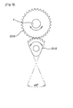
- FIG. 1 is a schematic diagram of an automatic speed control system for a manual transmission according to the present invention
- FIG. 2 is a view showing clutch operating means of the automatic speed control system for the manual transmission
- FIG. 3 is a view showing an engagement state of gears of FIG. 2
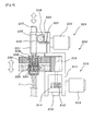
- FIG. 4 is a view showing control shaft operating means of the automatic speed control system for the manual transmission
- FIG. 5 is a view showing an operated state by selector operating means of FIG. 4
- FIG. 6 is a view showing an operated state by shift operating means of FIG. 4
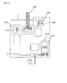
- FIG. 7 is a view showing an installation state of the automatic speed control system for the manual transmission.
- the automatic speed control system for the manual transmission includes a control part 100, clutch operating means 200, and control shaft operating means 300.
- the clutch operating means 200 operates a clutch lever 8 to selectively separate a clutch disk from a rotary power of an engine 30, and the control shaft operating means 300 operates a control shaft 1 to shift a manual gear when the clutch disk is separated from the rotary power of the engine by the clutch operating means 200.
- control part 100 checks a driving state of a vehicle in real time, and if a gear shift is needed, controls the clutch operating means 200, and then, controls the control shaft operating means 300 so as to automatically shift a gear of the manual transmission 10.
- the control unit 100 measures at least one selected from speed and engine rpm of the vehicle, rpm acceleration position of a driving shaft, whether or not a brake is operated, and a position of the gear in real time, and then, controls the clutch operating means 200 and the control shaft operating means 300.
- control part 100 measures operation conditions of components of the vehicle and controls the clutch operating means 200 and the control shaft operating means 300, and hence, for this, each component of the vehicle has a sensor.
- an acceleration sensor for measuring an operation position of an accelerator of the vehicle
- a low speed sensor for checking a continuous low speed state of the vehicle
- a brake sensor for measuring an operation position of a brake
- an engine start sensor for measuring an engine start state
- a side sensor for measuring a position of a side brake
- a gear position sensor for measuring a position of the gear of a gear-shifting part.
- Measurement values of the acceleration sensor, the low speed sensor, the brake sensor, the engine start sensor, the side sensor, and the gear position sensor are transferred to the control part 100 in real time, and hence, the clutch operating means 200 and the control shaft operating means 300 are easily controlled so as to automatically shift the gear.
- the sensors are not illustrated.
- the clutch operating means 200 includes a frame 210, a worm 220, a worm gear 230, a pinion gear 240, and a rack gear 250.
- the worm 220 is rotatably disposed on the frame 210 and rotated by a driving motor 222, and the worm gear 230 is connected to the worm 220 so as to transfer a rotary power in a perpendicular direction.
- the pinion gear 240 is located on the same axis in such a way as to be rotated in the same way as the worm gear 230, and the rack gear 250 is geared to the pinion gear 240 and moves to operate the clutch lever 8.
- the driving motor 222 further includes a low speed sensor 260, and the low speed sensor 260 measures rpm of the driving motor 222 and transfers the measured value to the control part 100 to thereby control the clutch operating means 200.
- the frame 210 includes a position sensor 270, and the position sensor 270 measures rpm of the worm gear 230 or the pinion gear 240 and transfers the measured value to the control part 100 to thereby control the clutch operating means 200.
- the position sensor 270 includes a variable resistance TPS (Throttle Position Sensor) to transfer the measured value to an ECU (Electronic Control Unit), and the measured value transferred to the ECU is transferred to the control part 100 to thereby control the clutch operating means 200.
- TPS Three Position Sensor
- Such a position sensor 270 also measures an idling state, an acceleration state, a deceleration state, a full-load state, and so on and transfers the measured values to the ECU.
- the ECU transfers the values to the control part 100 to thereby more easily control the clutch operating means 200.
- control shaft operating means 300 includes an operation gear 330, selector operating means 310, and shift operating means 320.
- the operation gear 330 is fixed at an end portion of the control shaft 1, and the selector operating means 310 rotates the operation gear 330 at a predetermined angle to thereby rotate the control shaft 1 relative to a central axis.
- the shift operating means 320 moves the operation gear 330 in a direction of the central axis to thereby move the control shaft 1 in a longitudinal direction.
- the selector operating means 310 includes a fixed block 311, a worm 312, a worm gear 314, and a connection gear 315.
- the worm 312 is rotatably disposed at the fixed block 311 and rotated by a driving motor 313, and the worm gear 314 is geared to the worm 312 to transfer a rotary power in a perpendicular direction.
- connection gear 315 is located on the same axis in such a way as to be rotated in the same way as the worm gear 314, and geared with the operation gear 330 so as to rotate the operation gear 330 at a predetermined angle, so that the control shaft 1 is rotated.
- the shift operating means 320 includes a fixed block 321, a worm 322, a worm gear 324, a pinion gear 325, and a movable shaft 326.
- the worm 322 is rotatably disposed at the fixed block 321 and rotated by a driving motor 323, and the worm gear 324 is geared to the worm 322 to transfer a rotary power in a perpendicular direction.
- the pinion gear 325 is located on the same axis in such a way as to be rotated in the same way as the worm gear 324, and the movable shaft 326 has a rack gear 327 geared with the pinion gear 325 and moves in a longitudinal direction.
- the operation gear 330 is rotatably connected to an end portion of the movable shaft 326, and hence, is rotated relative to a central axis thereof.
- the operation gear 330 is connected to the control shaft 1 by an operation bearing 332 and a first fixing member 334 and a fixing bracket 336 and a second fixing member 338.
- the operation bearing 332 is disposed between the operation gear 330 and the movable shaft 326 so that the operation gear 330 is rotatable, and the first fixing member 334 combines the operation gear 330 to the movable shaft 326.
- the operation gear 330 is rotatably joined to the movable shaft 326 in such a way as to be prevented from being separated by the first fixing member 334.
- the fixing bracket 336 and the second fixing member 338 are provided to fix the operation gear 330 and the control shaft 1.
- the fixing bracket 336 is fixed to the control shaft 1 so as to rotate in the same way as the control shaft 1, and is fixed to the operation gear 330 by the second fixing member 338 so as to rotate in the same way as the selector operating means 310 when the selector operating means 310 is operated.
- the operation gear 330 is rotatably disposed at an end of the movable shaft 326 of the shift operating means 310, so that the operation gear 330 can be rotated when the selector operating means 310 is operated.
- connection gear 315 of the selector operating means 310 is longer than the thickness of the operation gear 330, so that the operation gear 330 can move along a longitudinal direction of a gear thread of the connection gear 315.
- the selector operating means 310 and the shift operating means 320 respectively further include position sensors 316 and 328, so that the position sensors 316 and 328 respectively measure rpm of the selector operating means 310 and the shift operating means 320 and transfer the measured values to the control part 100 so as to control the control shaft operating means 300 in real time.
- the position sensors 316 and 328 respectively include variable resistance TPSs (Throttle Position Sensor) to transfer the measured values to an ECU (Electronic Control Unit), and the measured values transferred to the ECU is transferred to the control part 100 to thereby control the control shaft operating means 300.
- TPSs Three Position Sensor
- Such position sensors 316 and 328 also measure an idling state, an acceleration state, a deceleration state, a full-load state, and so on and transfer the measured values to the ECU.
- the ECU transfers the values to the control part 100 to thereby more easily control the control shaft operating means 300.
- the clutch lever and the control shaft 1 are operated in order by the clutch operating means 200, the control shaft operating means 300, and the control part 100 that controls the clutch operating means 200 and the control shaft operating means 300, such that the gears of the manual transmission can be automatically shifted.
Landscapes
- Engineering & Computer Science (AREA)
- Mechanical Engineering (AREA)
- General Engineering & Computer Science (AREA)
- Transportation (AREA)
- Chemical & Material Sciences (AREA)
- Combustion & Propulsion (AREA)
- Physics & Mathematics (AREA)
- Electromagnetism (AREA)
- Automation & Control Theory (AREA)
- Control Of Transmission Device (AREA)
- Gear-Shifting Mechanisms (AREA)
- Hydraulic Clutches, Magnetic Clutches, Fluid Clutches, And Fluid Joints (AREA)
- Arrangement And Mounting Of Devices That Control Transmission Of Motive Force (AREA)
- Transmission Devices (AREA)
- Arrangement Or Mounting Of Control Devices For Change-Speed Gearing (AREA)
Applications Claiming Priority (2)
| Application Number | Priority Date | Filing Date | Title |
|---|---|---|---|
| KR1020100000739A KR101185813B1 (ko) | 2010-01-06 | 2010-01-06 | 수동변속기 장착용 자동변속장치 |
| PCT/KR2010/009581 WO2011083935A2 (ko) | 2010-01-06 | 2010-12-30 | 수동변속기 장착용 자동변속장치 |
Publications (2)
| Publication Number | Publication Date |
|---|---|
| EP2522883A2 true EP2522883A2 (de) | 2012-11-14 |
| EP2522883A4 EP2522883A4 (de) | 2013-08-21 |
Family
ID=44305915
Family Applications (1)
| Application Number | Title | Priority Date | Filing Date |
|---|---|---|---|
| EP10842315.3A Withdrawn EP2522883A4 (de) | 2010-01-06 | 2010-12-30 | An ein schaltgetriebe montierbare automatikgetriebevorrichtung |
Country Status (6)
| Country | Link |
|---|---|
| US (1) | US8721497B2 (de) |
| EP (1) | EP2522883A4 (de) |
| JP (1) | JP5578340B2 (de) |
| KR (1) | KR101185813B1 (de) |
| CN (1) | CN102713362A (de) |
| WO (1) | WO2011083935A2 (de) |
Cited By (1)
| Publication number | Priority date | Publication date | Assignee | Title |
|---|---|---|---|---|
| TWI717252B (zh) * | 2020-04-06 | 2021-01-21 | 介隆興齒輪股份有限公司 | 線性運動電控盒 |
Families Citing this family (13)
| Publication number | Priority date | Publication date | Assignee | Title |
|---|---|---|---|---|
| KR101185813B1 (ko) * | 2010-01-06 | 2012-10-02 | 동환산업 주식회사 | 수동변속기 장착용 자동변속장치 |
| WO2014077449A1 (ko) * | 2012-11-16 | 2014-05-22 | 동아하이테크 주식회사 | 변속형 구동장치 |
| CN103423436B (zh) * | 2013-09-05 | 2016-04-06 | 林会明 | 车用机械变速箱的电子换挡系统 |
| CN103423437B (zh) * | 2013-09-05 | 2017-01-04 | 江苏惠民交通设备有限公司 | 车用机械变速箱的电子换挡系统 |
| KR20150062441A (ko) * | 2013-11-29 | 2015-06-08 | 주식회사 만도 | 전자식 주차 브레이크 |
| JP6370606B2 (ja) * | 2014-05-23 | 2018-08-08 | Ntn株式会社 | 屈曲型加工ツール |
| CN104791479A (zh) * | 2015-04-02 | 2015-07-22 | 重庆钟华机械有限责任公司 | 一种用于纯电动汽车的双挡自动变速器总成 |
| KR101971187B1 (ko) * | 2017-03-21 | 2019-04-22 | 주식회사 카펙발레오 | 자동화 수동변속기의 구동장치 |
| CN107187447B (zh) * | 2017-05-29 | 2019-07-09 | 胡笳 | 一种基于车联网的车辆自适应巡航控制系统及其控制方法 |
| KR102611102B1 (ko) * | 2018-11-19 | 2023-12-07 | 미네베아미츠미 가부시키가이샤 | 엑츄에이터 및 이의 제어방법, 전자기기 |
| CN109915592A (zh) * | 2019-03-01 | 2019-06-21 | 吴有智 | 一种直线电驱动机构 |
| CN111677858B (zh) * | 2019-03-11 | 2023-01-31 | 舍弗勒技术股份两合公司 | 动力耦合控制装置 |
| CN114838062A (zh) * | 2022-04-12 | 2022-08-02 | 福建盛海智能科技有限公司 | 一种离合操纵机构 |
Family Cites Families (20)
| Publication number | Priority date | Publication date | Assignee | Title |
|---|---|---|---|---|
| DE1505535C3 (de) * | 1966-01-27 | 1978-09-21 | Robert Bosch Gmbh, 7000 Stuttgart | Selbsttätige elektrische Steuereinrichtung für ein Kraftfahrzeug-Zahnräderwechselgetriebe |
| FR2523743A1 (fr) * | 1982-03-18 | 1983-09-23 | Valeo | Commande pour un dispositif d'accouplement, tel qu'embrayage, variateur de vitesse, frein ou analogue |
| US4817468A (en) * | 1987-06-18 | 1989-04-04 | Ap Aero, Inc | Electric shift apparatus for manual transmission |
| US4981202A (en) * | 1988-03-17 | 1991-01-01 | Automotive Products Plc | Motor vehicle control system |
| JP2878881B2 (ja) * | 1991-10-07 | 1999-04-05 | 本田技研工業株式会社 | 常時噛合式変速機 |
| US5219391A (en) * | 1991-12-06 | 1993-06-15 | Eaton Corporation | Transmission shifter having automatic adjustment of control parameters |
| US5285360A (en) * | 1991-12-16 | 1994-02-08 | Textron Inc. | Automotive headlamp adjuster |
| BR9302458A (pt) * | 1993-07-08 | 1995-03-28 | Saulo Quaggio | Controlador computadorizado de mudanças de marchas e acionamento da embreagem para veículos automotores com caixa de câmbio manual |
| US6019009A (en) * | 1998-04-30 | 2000-02-01 | Hyundai Motor Co. | Driverless vehicle operating system for a vehicle equipped with a manual transmission |
| JP2002147602A (ja) * | 2000-11-15 | 2002-05-22 | Exedy Corp | 車両用変速機のギヤ変速装置 |
| JP2002147496A (ja) * | 2000-11-15 | 2002-05-22 | Exedy Corp | 車両用クラッチ駆動装置 |
| US6629589B2 (en) * | 2000-11-15 | 2003-10-07 | Exedy Corporation | Vehicle clutch driving device and gear shifting device of vehicle transmission |
| DE10232873A1 (de) * | 2002-07-19 | 2004-01-29 | Zf Friedrichshafen Ag | Elektromechanischer Getriebesteller |
| KR100446989B1 (ko) * | 2003-01-27 | 2004-09-01 | 백정호 | 수동변속기 장착용 자동변속장치 |
| TWI242506B (en) * | 2003-12-30 | 2005-11-01 | Ind Tech Res Inst | Automatic gear device |
| CN2688533Y (zh) * | 2004-01-12 | 2005-03-30 | 财团法人工业技术研究院 | 一种自动排档装置 |
| KR20050101973A (ko) * | 2004-04-20 | 2005-10-25 | 현대자동차주식회사 | 차량의 변속작동장치 |
| KR100697213B1 (ko) * | 2004-12-24 | 2007-03-21 | 에스디주식회사 | 수동변속기 장착용 클러치 |
| JP2007292112A (ja) * | 2006-04-21 | 2007-11-08 | Isuzu Motors Ltd | スプライン軸の支持装置 |
| KR101185813B1 (ko) * | 2010-01-06 | 2012-10-02 | 동환산업 주식회사 | 수동변속기 장착용 자동변속장치 |
-
2010
- 2010-01-06 KR KR1020100000739A patent/KR101185813B1/ko not_active Expired - Fee Related
- 2010-12-30 CN CN2010800609151A patent/CN102713362A/zh active Pending
- 2010-12-30 US US13/520,892 patent/US8721497B2/en not_active Expired - Fee Related
- 2010-12-30 JP JP2012547948A patent/JP5578340B2/ja not_active Expired - Fee Related
- 2010-12-30 WO PCT/KR2010/009581 patent/WO2011083935A2/ko not_active Ceased
- 2010-12-30 EP EP10842315.3A patent/EP2522883A4/de not_active Withdrawn
Cited By (1)
| Publication number | Priority date | Publication date | Assignee | Title |
|---|---|---|---|---|
| TWI717252B (zh) * | 2020-04-06 | 2021-01-21 | 介隆興齒輪股份有限公司 | 線性運動電控盒 |
Also Published As
| Publication number | Publication date |
|---|---|
| CN102713362A (zh) | 2012-10-03 |
| KR20110080487A (ko) | 2011-07-13 |
| JP5578340B2 (ja) | 2014-08-27 |
| US8721497B2 (en) | 2014-05-13 |
| JP2013516586A (ja) | 2013-05-13 |
| WO2011083935A2 (ko) | 2011-07-14 |
| EP2522883A4 (de) | 2013-08-21 |
| US20130072349A1 (en) | 2013-03-21 |
| KR101185813B1 (ko) | 2012-10-02 |
| WO2011083935A3 (ko) | 2011-11-10 |
Similar Documents
| Publication | Publication Date | Title |
|---|---|---|
| EP2522883A2 (de) | An ein schaltgetriebe montierbare automatikgetriebevorrichtung | |
| US8746104B2 (en) | Gear absolute position sensor for manual transmissions | |
| JP4450093B2 (ja) | シフト切換機構の異常判定装置および異常判定方法 | |
| US9322381B2 (en) | Remote start for manual transmissions | |
| US6199003B1 (en) | Apparatus and method for manually shifting an automatic transmission | |
| DE102007057526B4 (de) | Verfahren zum Steuern eines Motors und Kraftfahrzeug | |
| CN103313895A (zh) | 车辆动力传递控制装置 | |
| US8725336B2 (en) | Power transmission control device for vehicle | |
| EP0960036A1 (de) | Vorrichtung zur bestätigung der steuerung eines fahrzeuges | |
| JP2003514197A (ja) | クラッチ装置のための操作装置 | |
| US9719595B2 (en) | Active rev-matching for manual transmissions | |
| CN1123459C (zh) | 离合器误调节的确定 | |
| GB2448671A (en) | A method of controlling driveline backlash | |
| GB2438411A (en) | Hybrid vehicle having an automatic transmission with parking pawl load relieved by a motor | |
| CA2342492C (en) | Method of controlling continuously variable transmission | |
| JP2001099312A (ja) | 自動車用変速機 | |
| KR20140088389A (ko) | 자동 변속을 위한 수동변속기의 자동제어장치 | |
| CN103253270B (zh) | 一种减轻升挡时耸车的方法及装置 | |
| US9037361B2 (en) | Self adjusting shift cable alignment for a transmission range control module system | |
| JP2001099317A (ja) | 自動車用変速機 | |
| CA2442427C (en) | Method of controlling automatic transmission | |
| JP2001099318A (ja) | 自動車用変速機 | |
| JPS61129344A (ja) | 自動トランスミツシヨン | |
| JP2008215265A (ja) | 車両の表示装置 | |
| Jantos et al. | Automatic gear shift unit |
Legal Events
| Date | Code | Title | Description |
|---|---|---|---|
| PUAI | Public reference made under article 153(3) epc to a published international application that has entered the european phase |
Free format text: ORIGINAL CODE: 0009012 |
|
| 17P | Request for examination filed |
Effective date: 20120803 |
|
| AK | Designated contracting states |
Kind code of ref document: A2 Designated state(s): AL AT BE BG CH CY CZ DE DK EE ES FI FR GB GR HR HU IE IS IT LI LT LU LV MC MK MT NL NO PL PT RO RS SE SI SK SM TR |
|
| DAX | Request for extension of the european patent (deleted) | ||
| A4 | Supplementary search report drawn up and despatched |
Effective date: 20130723 |
|
| RIC1 | Information provided on ipc code assigned before grant |
Ipc: F16H 59/06 20060101AFI20130717BHEP Ipc: F16H 63/00 20060101ALI20130717BHEP Ipc: B60K 20/02 20060101ALI20130717BHEP Ipc: F16H 61/32 20060101ALI20130717BHEP Ipc: F16H 59/00 20060101ALI20130717BHEP |
|
| STAA | Information on the status of an ep patent application or granted ep patent |
Free format text: STATUS: THE APPLICATION IS DEEMED TO BE WITHDRAWN |
|
| 18D | Application deemed to be withdrawn |
Effective date: 20170701 |