EP2522919A2 - Procédé de commande d'un climatiseur multi-bloc - Google Patents
Procédé de commande d'un climatiseur multi-bloc Download PDFInfo
- Publication number
- EP2522919A2 EP2522919A2 EP20120161511 EP12161511A EP2522919A2 EP 2522919 A2 EP2522919 A2 EP 2522919A2 EP 20120161511 EP20120161511 EP 20120161511 EP 12161511 A EP12161511 A EP 12161511A EP 2522919 A2 EP2522919 A2 EP 2522919A2
- Authority
- EP
- European Patent Office
- Prior art keywords
- indoor
- indoor unit
- mode
- pipe port
- indoor units
- Prior art date
- Legal status (The legal status is an assumption and is not a legal conclusion. Google has not performed a legal analysis and makes no representation as to the accuracy of the status listed.)
- Granted
Links
Images





Classifications
-
- F—MECHANICAL ENGINEERING; LIGHTING; HEATING; WEAPONS; BLASTING
- F24—HEATING; RANGES; VENTILATING
- F24F—AIR-CONDITIONING; AIR-HUMIDIFICATION; VENTILATION; USE OF AIR CURRENTS FOR SCREENING
- F24F11/00—Control or safety arrangements
- F24F11/30—Control or safety arrangements for purposes related to the operation of the system, e.g. for safety or monitoring
-
- F—MECHANICAL ENGINEERING; LIGHTING; HEATING; WEAPONS; BLASTING
- F24—HEATING; RANGES; VENTILATING
- F24F—AIR-CONDITIONING; AIR-HUMIDIFICATION; VENTILATION; USE OF AIR CURRENTS FOR SCREENING
- F24F11/00—Control or safety arrangements
- F24F11/50—Control or safety arrangements characterised by user interfaces or communication
- F24F11/52—Indication arrangements, e.g. displays
-
- F—MECHANICAL ENGINEERING; LIGHTING; HEATING; WEAPONS; BLASTING
- F24—HEATING; RANGES; VENTILATING
- F24F—AIR-CONDITIONING; AIR-HUMIDIFICATION; VENTILATION; USE OF AIR CURRENTS FOR SCREENING
- F24F11/00—Control or safety arrangements
- F24F11/50—Control or safety arrangements characterised by user interfaces or communication
- F24F11/54—Control or safety arrangements characterised by user interfaces or communication using one central controller connected to several sub-controllers
-
- F—MECHANICAL ENGINEERING; LIGHTING; HEATING; WEAPONS; BLASTING
- F24—HEATING; RANGES; VENTILATING
- F24F—AIR-CONDITIONING; AIR-HUMIDIFICATION; VENTILATION; USE OF AIR CURRENTS FOR SCREENING
- F24F11/00—Control or safety arrangements
- F24F11/62—Control or safety arrangements characterised by the type of control or by internal processing, e.g. using fuzzy logic, adaptive control or estimation of values
-
- F—MECHANICAL ENGINEERING; LIGHTING; HEATING; WEAPONS; BLASTING
- F24—HEATING; RANGES; VENTILATING
- F24F—AIR-CONDITIONING; AIR-HUMIDIFICATION; VENTILATION; USE OF AIR CURRENTS FOR SCREENING
- F24F11/00—Control or safety arrangements
- F24F11/62—Control or safety arrangements characterised by the type of control or by internal processing, e.g. using fuzzy logic, adaptive control or estimation of values
- F24F11/63—Electronic processing
- F24F11/64—Electronic processing using pre-stored data
-
- F—MECHANICAL ENGINEERING; LIGHTING; HEATING; WEAPONS; BLASTING
- F24—HEATING; RANGES; VENTILATING
- F24F—AIR-CONDITIONING; AIR-HUMIDIFICATION; VENTILATION; USE OF AIR CURRENTS FOR SCREENING
- F24F11/00—Control or safety arrangements
- F24F11/62—Control or safety arrangements characterised by the type of control or by internal processing, e.g. using fuzzy logic, adaptive control or estimation of values
- F24F11/63—Electronic processing
- F24F11/65—Electronic processing for selecting an operating mode
-
- F—MECHANICAL ENGINEERING; LIGHTING; HEATING; WEAPONS; BLASTING
- F24—HEATING; RANGES; VENTILATING
- F24F—AIR-CONDITIONING; AIR-HUMIDIFICATION; VENTILATION; USE OF AIR CURRENTS FOR SCREENING
- F24F11/00—Control or safety arrangements
- F24F11/70—Control systems characterised by their outputs; Constructional details thereof
- F24F11/80—Control systems characterised by their outputs; Constructional details thereof for controlling the temperature of the supplied air
- F24F11/83—Control systems characterised by their outputs; Constructional details thereof for controlling the temperature of the supplied air by controlling the supply of heat-exchange fluids to heat-exchangers
- F24F11/84—Control systems characterised by their outputs; Constructional details thereof for controlling the temperature of the supplied air by controlling the supply of heat-exchange fluids to heat-exchangers using valves
-
- F—MECHANICAL ENGINEERING; LIGHTING; HEATING; WEAPONS; BLASTING
- F24—HEATING; RANGES; VENTILATING
- F24F—AIR-CONDITIONING; AIR-HUMIDIFICATION; VENTILATION; USE OF AIR CURRENTS FOR SCREENING
- F24F3/00—Air-conditioning systems in which conditioned primary air is supplied from one or more central stations to distributing units in the rooms or spaces where it may receive secondary treatment; Apparatus specially designed for such systems
- F24F3/06—Air-conditioning systems in which conditioned primary air is supplied from one or more central stations to distributing units in the rooms or spaces where it may receive secondary treatment; Apparatus specially designed for such systems characterised by the arrangements for the supply of heat-exchange fluid for the subsequent treatment of primary air in the room units
- F24F3/065—Air-conditioning systems in which conditioned primary air is supplied from one or more central stations to distributing units in the rooms or spaces where it may receive secondary treatment; Apparatus specially designed for such systems characterised by the arrangements for the supply of heat-exchange fluid for the subsequent treatment of primary air in the room units with a plurality of evaporators or condensers
-
- F—MECHANICAL ENGINEERING; LIGHTING; HEATING; WEAPONS; BLASTING
- F25—REFRIGERATION OR COOLING; COMBINED HEATING AND REFRIGERATION SYSTEMS; HEAT PUMP SYSTEMS; MANUFACTURE OR STORAGE OF ICE; LIQUEFACTION SOLIDIFICATION OF GASES
- F25B—REFRIGERATION MACHINES, PLANTS OR SYSTEMS; COMBINED HEATING AND REFRIGERATION SYSTEMS; HEAT PUMP SYSTEMS
- F25B13/00—Compression machines, plants or systems, with reversible cycle
-
- F—MECHANICAL ENGINEERING; LIGHTING; HEATING; WEAPONS; BLASTING
- F25—REFRIGERATION OR COOLING; COMBINED HEATING AND REFRIGERATION SYSTEMS; HEAT PUMP SYSTEMS; MANUFACTURE OR STORAGE OF ICE; LIQUEFACTION SOLIDIFICATION OF GASES
- F25B—REFRIGERATION MACHINES, PLANTS OR SYSTEMS; COMBINED HEATING AND REFRIGERATION SYSTEMS; HEAT PUMP SYSTEMS
- F25B41/00—Fluid-circulation arrangements
- F25B41/30—Expansion means; Dispositions thereof
- F25B41/31—Expansion valves
-
- F—MECHANICAL ENGINEERING; LIGHTING; HEATING; WEAPONS; BLASTING
- F25—REFRIGERATION OR COOLING; COMBINED HEATING AND REFRIGERATION SYSTEMS; HEAT PUMP SYSTEMS; MANUFACTURE OR STORAGE OF ICE; LIQUEFACTION SOLIDIFICATION OF GASES
- F25B—REFRIGERATION MACHINES, PLANTS OR SYSTEMS; COMBINED HEATING AND REFRIGERATION SYSTEMS; HEAT PUMP SYSTEMS
- F25B41/00—Fluid-circulation arrangements
- F25B41/30—Expansion means; Dispositions thereof
- F25B41/31—Expansion valves
- F25B41/34—Expansion valves with the valve member being actuated by electric means, e.g. by piezoelectric actuators
-
- F—MECHANICAL ENGINEERING; LIGHTING; HEATING; WEAPONS; BLASTING
- F25—REFRIGERATION OR COOLING; COMBINED HEATING AND REFRIGERATION SYSTEMS; HEAT PUMP SYSTEMS; MANUFACTURE OR STORAGE OF ICE; LIQUEFACTION SOLIDIFICATION OF GASES
- F25B—REFRIGERATION MACHINES, PLANTS OR SYSTEMS; COMBINED HEATING AND REFRIGERATION SYSTEMS; HEAT PUMP SYSTEMS
- F25B5/00—Compression machines, plants or systems, with several evaporator circuits, e.g. for varying refrigerating capacity
- F25B5/02—Compression machines, plants or systems, with several evaporator circuits, e.g. for varying refrigerating capacity arranged in parallel
-
- F—MECHANICAL ENGINEERING; LIGHTING; HEATING; WEAPONS; BLASTING
- F25—REFRIGERATION OR COOLING; COMBINED HEATING AND REFRIGERATION SYSTEMS; HEAT PUMP SYSTEMS; MANUFACTURE OR STORAGE OF ICE; LIQUEFACTION SOLIDIFICATION OF GASES
- F25B—REFRIGERATION MACHINES, PLANTS OR SYSTEMS; COMBINED HEATING AND REFRIGERATION SYSTEMS; HEAT PUMP SYSTEMS
- F25B2313/00—Compression machines, plants or systems with reversible cycle not otherwise provided for
- F25B2313/007—Compression machines, plants or systems with reversible cycle not otherwise provided for three pipes connecting the outdoor side to the indoor side with multiple indoor units
-
- F—MECHANICAL ENGINEERING; LIGHTING; HEATING; WEAPONS; BLASTING
- F25—REFRIGERATION OR COOLING; COMBINED HEATING AND REFRIGERATION SYSTEMS; HEAT PUMP SYSTEMS; MANUFACTURE OR STORAGE OF ICE; LIQUEFACTION SOLIDIFICATION OF GASES
- F25B—REFRIGERATION MACHINES, PLANTS OR SYSTEMS; COMBINED HEATING AND REFRIGERATION SYSTEMS; HEAT PUMP SYSTEMS
- F25B2313/00—Compression machines, plants or systems with reversible cycle not otherwise provided for
- F25B2313/023—Compression machines, plants or systems with reversible cycle not otherwise provided for using multiple indoor units
- F25B2313/0231—Compression machines, plants or systems with reversible cycle not otherwise provided for using multiple indoor units with simultaneous cooling and heating
-
- F—MECHANICAL ENGINEERING; LIGHTING; HEATING; WEAPONS; BLASTING
- F25—REFRIGERATION OR COOLING; COMBINED HEATING AND REFRIGERATION SYSTEMS; HEAT PUMP SYSTEMS; MANUFACTURE OR STORAGE OF ICE; LIQUEFACTION SOLIDIFICATION OF GASES
- F25B—REFRIGERATION MACHINES, PLANTS OR SYSTEMS; COMBINED HEATING AND REFRIGERATION SYSTEMS; HEAT PUMP SYSTEMS
- F25B2313/00—Compression machines, plants or systems with reversible cycle not otherwise provided for
- F25B2313/023—Compression machines, plants or systems with reversible cycle not otherwise provided for using multiple indoor units
- F25B2313/0233—Compression machines, plants or systems with reversible cycle not otherwise provided for using multiple indoor units in parallel arrangements
-
- F—MECHANICAL ENGINEERING; LIGHTING; HEATING; WEAPONS; BLASTING
- F25—REFRIGERATION OR COOLING; COMBINED HEATING AND REFRIGERATION SYSTEMS; HEAT PUMP SYSTEMS; MANUFACTURE OR STORAGE OF ICE; LIQUEFACTION SOLIDIFICATION OF GASES
- F25B—REFRIGERATION MACHINES, PLANTS OR SYSTEMS; COMBINED HEATING AND REFRIGERATION SYSTEMS; HEAT PUMP SYSTEMS
- F25B2313/00—Compression machines, plants or systems with reversible cycle not otherwise provided for
- F25B2313/027—Compression machines, plants or systems with reversible cycle not otherwise provided for characterised by the reversing means
- F25B2313/02741—Compression machines, plants or systems with reversible cycle not otherwise provided for characterised by the reversing means using one four-way valve
-
- F—MECHANICAL ENGINEERING; LIGHTING; HEATING; WEAPONS; BLASTING
- F25—REFRIGERATION OR COOLING; COMBINED HEATING AND REFRIGERATION SYSTEMS; HEAT PUMP SYSTEMS; MANUFACTURE OR STORAGE OF ICE; LIQUEFACTION SOLIDIFICATION OF GASES
- F25B—REFRIGERATION MACHINES, PLANTS OR SYSTEMS; COMBINED HEATING AND REFRIGERATION SYSTEMS; HEAT PUMP SYSTEMS
- F25B2600/00—Control issues
- F25B2600/25—Control of valves
- F25B2600/2513—Expansion valves
-
- Y—GENERAL TAGGING OF NEW TECHNOLOGICAL DEVELOPMENTS; GENERAL TAGGING OF CROSS-SECTIONAL TECHNOLOGIES SPANNING OVER SEVERAL SECTIONS OF THE IPC; TECHNICAL SUBJECTS COVERED BY FORMER USPC CROSS-REFERENCE ART COLLECTIONS [XRACs] AND DIGESTS
- Y02—TECHNOLOGIES OR APPLICATIONS FOR MITIGATION OR ADAPTATION AGAINST CLIMATE CHANGE
- Y02B—CLIMATE CHANGE MITIGATION TECHNOLOGIES RELATED TO BUILDINGS, e.g. HOUSING, HOUSE APPLIANCES OR RELATED END-USER APPLICATIONS
- Y02B30/00—Energy efficient heating, ventilation or air conditioning [HVAC]
- Y02B30/70—Efficient control or regulation technologies, e.g. for control of refrigerant flow, motor or heating
Definitions
- the present disclosure relates to a method of controlling the multi type air conditioner.
- Air conditioners include a refrigerant cycle of a compressor, a condenser, an expansion mechanism, and an evaporator to heat/cool an indoor space or purify air, thereby providing comfort indoor environment to users.
- Air conditioners are classified into air conditioners in which a single indoor unit is connected to a single outdoor unit, and multi type air conditioners in which a plurality of indoor units are connected to a single outdoor unit to provide the effect of a plurality of air conditioners.
- simultaneous heating/cooling air conditioners which include a distributor between an outdoor unit and indoor units to control refrigerant flow.
- a part of the indoor units cool an indoor space, and the rest thereof heats an indoor space.
- Such a distributor may include a plurality of pipe ports. In this case, only one indoor unit is connected to one pipe port. Thus, the number of distributors should be increased to increase the number of indoor units, which increases material and installation costs for additional distributors.
- the present invention provides a method of controlling a multi type air conditioner, in which a plurality of indoor units are connected to a pipe port of a distributor according to claim 1. Preferred embodiments are defined in the dependent claims.
- a method of controlling a multi type air conditioner including: an outdoor unit; a distributor connected to the outdoor unit and including pipe ports; and a plurality of indoor units connected to the distributor, wherein two or more of the indoor units are connected to one or more of the pipe ports to constitute an indoor unit group of each pipe port, includes: inputting an operation command to one or more of the indoor units constituting the indoor unit group; checking a reference mode of the indoor unit group; and imitating the reference mode to operate the one or more indoor units.
- Fig. 1 is a schematic view illustrating a multi type air conditioner according to an embodiment.
- Fig. 2 is a schematic view illustrating a refrigerant cycle of a multi type air conditioner according to an embodiment.
- Fig. 3 is a schematic view illustrating refrigerant flow in a whole heating operation of a multi type air conditioner according to an embodiment.
- Fig. 4 is a schematic view illustrating refrigerant flow in a cooling-dominant operation of a multi type air conditioner according to an embodiment.
- Fig. 5 is a schematic view illustrating refrigerant flow in a heating-dominant operation of a multi type air conditioner according to an embodiment.
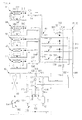
- Fig. 6 is a block diagram illustrating control of a multi type air conditioner according to an embodiment.
- Fig. 7 is a flowchart illustrating a method of searching for a tube of a multi type air conditioner according to an embodiment.
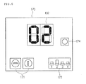
- Fig. 8 is a schematic view illustrating a display part and an input part of an outdoor unit according to an embodiment.
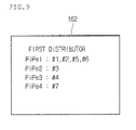
- Fig. 9 is a schematic view illustrating a display part according to an embodiment.
- Fig. 10 is a flowchart illustrating a method of controlling a multi type air conditioner according to an embodiment.
- Fig. 1 is a schematic view illustrating a multi type air conditioner according to an embodiment.
- a multi type air conditioner includes at least one outdoor unit 10, a plurality of indoor units 51 to 57, and one or more distributors 20 and 30 connecting the outdoor unit 10 to the indoor units 51 to 57.
- One outdoor unit is provided as the outdoor unit 10; two distributors are provided as the distributors 20 and 30; and seven indoor units are provided as the indoor units 51 to 57 at each of the distributors 20 and 30.
- the present disclosure is not limited to the number of indoor units, outdoor units, and distributors.
- First to fourth pipe ports 41, 42, 43, and 44 may be provided to each of the distributors 20 and 30.
- the number of pipe ports provided to each of the distributors 20 and 30 is not limited thereto.
- the first, second, and third indoor units 51, 52, and 53 are connected to the first, second, and third pipe ports 41, 42, and 43, respectively. Indoor units are connected in parallel to the fourth pipe port 44.
- the fourth, fifth, sixth, and seventh indoor units 54, 55, 56, and 57 may be connected to the fourth pipe port 44.
- the indoor units 54, 55, 56, and 57 may be connected to the fourth pipe port 44 may be referred to as grouped indoor units, or an indoor unit group.
- a plurality of indoor units are connected to the fourth pipe port 44 according to the current embodiment, a plurality of indoor units may be connected to a plurality of pipe ports, respectively.
- Fig. 2 is a schematic view illustrating a refrigerant cycle of a multi type air conditioner according to an embodiment.
- a first indoor unit 51 and fourth to seventh indoor units 54 and 57 connected to a distributor 20 or 30 are illustrated in Fig. 2 , and second and third indoor units 52 and 53 (refer to Fig. 1 ) are not illustrated.
- an outdoor unit 10 includes a compressor part 110, an outdoor heat exchanger 140, an outdoor expansion mechanism 150, and a switching valve 130.
- the compressor part 110 includes one or more compressors for compressing refrigerant.
- compressors 111 and 112 are exemplified as the compressors of the compressor part 110.
- the compressors 111 and 112 may include an inverter compressor (also denoted by 111) having variable capacity, and a constant-speed compressor (also denoted by 112).
- the compressors 111 and 112 may be arrayed in parallel.
- An intake tube 131 of the compressors 111 and 112 is connected to the switching valve 130.
- An accumulator 132 is installed on the intake tube 131.
- Discharge passages of the compressors 111 and 112 may be provided with oil separators 113 and 114 for separating oil from the refrigerant, and a discharge distributor 120 connected to the switching valve 130 and the distributors 20 and 30. Oil separated from the refrigerant by the oil separators 113 and 114 may be recovered to the compressor part 110.
- the discharge distributor 120 distributes the refrigerant discharged from the compressors 111 and 112 to the switching valve 130 and the distributors 20 and 30.
- the discharge distributor 120 is connected to the distributors 20 and 30 through a high pressure gas tube 181.
- the discharge distributor 120 is connected to the switching valve 130 through a first connecting tube 121, and is connected to the oil separators 113 and 114 through second connecting tubes 122.
- the outdoor heat exchanger 140 may function as a condenser in a whole cooling operation or a cooling-dominant operation, and function as an evaporator in a whole heating operation or a heating-dominant operation.
- the whole cooling operation denotes that all indoor units perform a cooling operation
- the whole heating operation denotes that all indoor units perform a heating operation.
- the cooling-dominant operation denotes that capacity of indoor units performing a cooling operation is greater than capacity of indoor units performing a heating operation.
- the heating-dominant operation denotes that capacity of indoor units performing a heating operation is greater than capacity of indoor units performing a cooling operation.
- the refrigerant within the outdoor heat exchanger 140 may exchange heat with outdoor air blown by an outdoor fan (not shown).
- the refrigerant After being discharged from the outdoor heat exchanger 140, the refrigerant is not expanded by the outdoor expansion mechanism 150. Before being introduced to the outdoor heat exchanger 140, the refrigerant is expanded by the outdoor expansion mechanism 150.
- the outdoor expansion mechanism 150 may include an outdoor expansion valve between the outdoor heat exchanger 140 and the distributors 20 and 30, or include an outdoor expansion valve 152 and a check valve 154 with refrigerant passages connected in parallel between a refrigerant passage of the outdoor heat exchanger 140 and the distributors 20 and 30.
- the outdoor expansion valve 152 may be an electronic expansion valve (EEV).
- the switching valve 130 in the whole cooling operation or the cooling-dominant operation, allows the refrigerant compressed by the compressors 111 and 112 to flow to the outdoor heat exchanger 140, and, in the whole heating operation or the heating-dominant operation, allows the refrigerant discharged from the outdoor heat exchanger 140 to flow to the compressors 111 and 112.
- the outdoor expansion mechanism 150 is connected to the distributors 20 and 30 through a liquid tube 182.
- the intake tube 131 is connected to the distributors 20 and 30 through a low pressure gas tube 183.
- the first to third indoor units 51 to 53 may independently perform a cooling or heating operation.
- the fourth to seventh indoor units 54 to 57 may perform a cooling or heating operation together.
- Each of the indoor units 51 to 57 includes: an indoor heat exchanger 511 or 541 in which the refrigerant exchanges heat with indoor air to cool or heat the indoor air; an indoor fan 512 or 542 introducing indoor air into a corresponding one of the indoor units 51 to 37 for heat exchange in the indoor heat exchanger 511 or 541, and then, discharging the indoor air from the corresponding indoor unit; and an indoor expansion mechanism 513 or 543 expanding the refrigerant flowing to the indoor heat exchanger 511 or 541.
- the indoor expansion mechanisms 513 and 543 may be electronic expansion valves capable of adjusting the flow rate of refrigerant.
- the electronic expansion valves may control the degree of opening to adjust the flow rate of refrigerant.
- the distributors 20 and 30 include a low pressure gas pipe 310, a liquid pipe 312, and a high pressure gas pipe 314.
- the low pressure gas pipe 310, the liquid pipe 312, and the high pressure gas pipe 314 are connected to the outdoor unit 10 through the low pressure gas tube 183, the liquid tube 182, and the high pressure gas tube 181, respectively.
- the low pressure gas pipe 310, the liquid pipe 312, and the high pressure gas pipe 314 are connected to the indoor units 51 to 57 through first to fourth pipe ports 41 to 44.
- Each of the first to third pipe ports 41 to 43 includes an indoor gas tube 514 and an indoor liquid tube 515.
- the fourth pipe port 44 includes: a common indoor gas tube 544; a common indoor liquid tube 545; a plurality of individual indoor gas tubes 546 branching from the common indoor gas tube 544 and connecting to the fourth to seventh indoor units 54 to 57, respectively; and a plurality of individual indoor liquid tubes 547 branching from the common indoor liquid tube 545 and connecting to the fourth to seventh indoor units 54 to 57, respectively.
- Low pressure valves 321 and 331 are installed on the indoor gas tubes 514 and the common indoor gas tube 544 to control refrigerant flow between the low pressure gas pipe 310 and the indoor units 51 to 57.
- the high pressure gas pipe 314 are connected to the pipe ports 41 to 44, particularly, to the indoor gas tubes 514 and the common indoor gas tube 544 through branch tubes 323 and 333.
- High pressure valves 322 and 332 are disposed on the branch tubes 323 and 333 to control refrigerant flow between the high pressure gas pipe 314 and the indoor units 51 to 57.
- the low pressure valves 321 and 331 When the indoor units 51 to 57 connected to the pipe ports 41 to 44 are in a cooling operation, the low pressure valves 321 and 331 may be opened, and the high pressure valves 322 and 332 may be closed. On the contrary, when the indoor units 51 to 57 connected to the pipe ports 41 to 44 are in a heating operation, the low pressure valves 321 and 331 may be closed, and the high pressure valves 322 and 332 may be opened.
- the low pressure valves 321 and 331, and the high pressure valves 322 and 332 may be electronic expansion valves to adjust the degree of opening linearly or in a stepwise fashion.
- the refrigerant compressed by the compressors 111 and 112 sequentially pass through the switching valve 130 and the outdoor heat exchanger 140 by the discharge distributor 120, and then, flows from the outdoor unit 10 to the liquid pipe 312 of the distributors 20 and 30 through the liquid tube 182.
- the refrigerant arriving at the liquid pipe 312 flows to the indoor expansion mechanisms 513 and 543 of the indoor units 51 to 57, which are in the whole cooling operation, through the indoor liquid tubes 547 and 515.
- the refrigerant is expanded by the indoor expansion mechanisms 513 and 543, and then, is evaporated by the indoor heat exchangers 511 and 541.
- the evaporated refrigerant flows from the indoor units 51 to 57 to the low pressure gas pipe 310 of the distributors 20 and 30 through the indoor gas tubes 514 and 544.
- the refrigerant arriving at the low pressure gas pipe 310 are introduced to the compressors 111 and 112 of the outdoor unit 10 through the low pressure gas tube 183.
- Fig. 3 is a schematic view illustrating refrigerant flow in a whole heating operation of a multi type air conditioner according to an embodiment.
- the refrigerant compressed by the compressors 111 and 112 pass through the discharge distributor 120, and then, flows from the outdoor unit 10 to the high pressure gas pipe 314 4 of the distributors 20 and 30 through the high pressure gas tube 181.
- the refrigerant arriving at the high pressure gas pipe 314 are introduced to the indoor heat exchanger 511 and 541 of the indoor units 51 to 57 through the indoor gas tubes 514 and 544, then, is condensed by the indoor heat exchangers 511 and 541, and then, passes through the indoor expansion mechanisms 513 and 543 without expansion. Then, the refrigerant flows from the indoor units 51 to 57 to the liquid pipe 312 of the distributors 20 and 30 through the indoor liquid tubes 515 and 547.
- the refrigerant arriving at the liquid pipe 312 is introduced to the outdoor expansion mechanism 150 of the outdoor unit 10 through the liquid tube 182, and is expanded by the outdoor expansion mechanism 150. Then, the expanded refrigerant is evaporated by the outdoor heat exchanger 140, and is introduced to the compressors 111 and 112 through the switching valve 130.
- Fig. 4 is a schematic view illustrating refrigerant flow in a cooling-dominant operation of a multi type air conditioner according to an embodiment.
- the first indoor unit 51 is in a heating operation
- the second to seventh indoor units 52 to 57 are in a cooling operation.
- the low pressure valves 321 and 331 corresponding to the second to seventh indoor units 52 to 57 in the cooling operation are opened, and the high pressure valves 322 and 332 corresponding thereto are closed.
- the low pressure valve 321 corresponding to the first indoor unit 51 in the heating operation is closed, and the high pressure valve 322 corresponding thereto is opened.
- the refrigerant compressed by the compressors 111 and 112 is divided by the discharge distributor 120, and a portion of the refrigerant sequentially passes through the switching valve 130 and the outdoor heat exchanger 140, and then, flows from the outdoor unit 10 to the liquid pipe 312 of the distributors 20 and 30 through the liquid tube 182.
- the refrigerant arriving at the liquid pipe 312 flows to the indoor expansion mechanisms 513 and 543 of the indoor units 52 to 57, which are in the cooling operation, through the indoor liquid tubes 547 and 515. Then, the refrigerant is expanded by the indoor expansion mechanisms 513 and 543, and then, is evaporated by the indoor heat exchangers 511 and 541.
- the evaporated refrigerant flows from the indoor units 52 to 57, which are in the cooling operation, to the low pressure gas pipe 310 of the distributors 20 and 30 through the indoor gas tubes 514 and 544, and then, is introduced to the compressors 111 and 112 of the outdoor unit 10 through the low pressure gas tube 183.
- the other portion of the refrigerant divided by the discharge distributor 120 flows to the high pressure gas pipe 314 of the distributors 20 and 30 through the high pressure gas tube 181, and is introduced to the indoor heat exchanger 511 of the indoor unit 51, which is in the heating operation, through the high pressure valve 322, and is condensed. Then, the condensed refrigerant passes through the indoor expansion mechanism 513 without expansion, and then flows to the liquid pipe 312 through the indoor liquid tube 515. Then, the refrigerant is mixed with the refrigerant flowing from the outdoor unit 10 to the liquid pipe 312 through the liquid tube 182.
- the indoor heat exchangers 511 and 541 of the indoor units 52 to 57 in the cooling operation function as evaporators to cool indoor spaces
- the indoor heat exchanger 511 of the indoor unit 51 in the cooling operation functions as a condenser to heat an indoor space.
- Fig. 5 is a schematic view illustrating refrigerant flow in a heating-dominant operation of a multi type air conditioner according to an embodiment.
- the first indoor unit 51 is in a cooling operation
- the second to seventh indoor units 52 to 57 are in a heating operation.
- the low pressure valves 321 and 331 corresponding to the second to seventh indoor units 52 to 57 in the heating operation are closed, and the high pressure valves 322 and 332 corresponding thereto are opened.
- the low pressure valve 321 corresponding to the first indoor unit 51 in the cooling operation is opened, and the high pressure valve 322 corresponding thereto is closed.
- the refrigerant compressed by the compressors 111 and 112 flows from the outdoor unit 10 to the high pressure gas pipe 314 of the distributors 20 and 30 through the high pressure gas tube 181, and is condensed by the indoor heat exchangers 511 and 541 of the indoor units 52 to 57 in the heating operation. Then, the condensed refrigerant passes through the indoor expansion mechanisms 513 and 543 without expansion, and flows from the indoor units 52 to 57 to the liquid pipe 312 of the distributors 20 and 30 through the indoor liquid tubes 515 and 547.
- the expanded refrigerant is evaporated by the indoor heat exchanger 511 of the indoor unit 51 in the cooling operation, then, flows to the low pressure gas pipe 310 through the indoor gas tube 514, and then, is introduced to the compressors 111 and 112 through the low pressure gas tube 183.
- the rest of the refrigerant flowing to the liquid pipe 312 is introduced to the outdoor expansion mechanism 150 of the outdoor unit 10 through the liquid tube 182, and is expanded. Then, the refrigerant is evaporated by the outdoor heat exchanger 140, and is introduced to the compressors 111 and 112 through the switching valve 130.
- Fig. 6 is a block diagram illustrating control of a multi type air conditioner according to an embodiment.
- the multi type air conditioner may include a control part 160, a display part 162 for displaying information, a memory 164 for storing information, a temperature sensor part 166 for sensing temperature, and an input part 170 for inputting a command.
- the control part 160 may include an indoor control part installed on the indoor units 51 to 57, an outdoor control part installed on the outdoor unit 10, and a distributor control part installed on the distributors 20 and 30.
- the control part 160 may include only a single control part installed on one of the outdoor unit 10 and the distributors 20 and 30.
- the control part 160 includes an outdoor control part installed on the outdoor unit 10, and a distributor control part installed on the distributors 20 and 30.
- the display part 162 may be provided to the outdoor unit 10. At least, the display part 162 may display information about the indoor units 51 to 57 connected to the pipe ports 41 to 44 of the distributors 20 and 30.
- the input part 170 may include a switch manipulated to check information about the indoor units 51 to 57 connected to the pipe ports 41 to 44 of the distributors 20 and 30.
- the input part 170 may be provided to the outdoor unit 10, or the distributor 20 or 30.
- the temperature sensor part 166 may sense temperature of the indoor gas tubes 514 and the common indoor gas tube 544 of the pipe ports 41 to 44. That is, the temperature sensor part 166 may be provided in plurality to correspond to the number of the pipe ports 41 to 44.
- the memory 164 may store temperature sensed by the temperature sensor part 166, and information about the indoor units 51 to 57 connected to the pipe ports 41 to 44 of the distributors 20 and 30.
- the memory 164 may be provided to the outdoor unit 10, or the distributor 20 or 30.
- Fig. 7 is a flowchart illustrating a method of searching for a tube of a multi type air conditioner according to an embodiment.
- the multi type air conditioner starts to perform a tube search process when the multi type air conditioner is driven first after installation, when the tube search process is requested by selecting a predetermined button provided to one of the outdoor unit 10, the distributors 20 and 30, and the indoor units 51 to 57, or when there is no matching data of the pipe ports 41 to 44 and the indoor units 51 to 57.
- the control part 160 transmits a tube search start command to the indoor units 51 to 57 and the distributors 20 and 30 such that all of the indoor units 51 to 57 perform a cooling operation.
- the low pressure valves 321 and 331 of the distributors 20 and 30 are opened all, and the high pressure valves 322 and 332 are closed all.
- the indoor expansion mechanisms 513 and 543 of the indoor units 51 to 57 are in a full open state (the degree of opening of 100).
- the temperature sensor parts 166 sense temperature of the indoor gas tubes 514 and the common indoor gas tube 544 in operation S3, and the sensed temperature is stored as an initial temperature in the memory 164.
- n and m denote a distributor number and a high pressure valve number, respectively, which are arbitrary numbers for conveniently describing sequential control of the distributors 20 and 30 and the high pressure valves 322 and 332, and an initial value of n and m is 1.
- a high pressure valve number is the same as a pipe port number of the pipe ports 41 to 44 of the distributors 20 and 30.
- a first high pressure valve provided to a first pipe port of a first distributor is opened, and a first low pressure valve provided to the first pipe port is closed. Then, the refrigerant in a high pressure gas state is introduced to one or more indoor units connected to the first pipe port, and thus, the indoor units perform a heating operation.
- the temperature sensor part 166 senses temperature of the indoor gas tubes 514 and the common indoor gas tubes 544 after a predetermined time.
- control part 160 compares the measured temperature with the initial temperature stored in the memory 164 to search for a temperature-varied indoor unit.
- the temperature-varied indoor unit has a temperature higher than the initial temperature.
- the temperature-varied indoor unit is matched with the m th high pressure valve of the n th distributor in operation S5.
- one or more indoor units may be connected to one pipe port as described above, when temperature of gas tubes of indoor units is varied, the indoor units can be matched with one pipe port.
- the degree of opening of the indoor expansion mechanism (indoor expansion valve) of the searched-for indoor unit is decreased to prevent the searched-for indoor unit from being re-searched for. That is, the degree of opening of the indoor expansion mechanism of the searched-for indoor unit is adjusted to be equal to or less than a certain degree of opening. Then, an indoor unit including the indoor expansion mechanism having a degree of opening equal to or less than the certain degree of opening is not searched for by the control part 160.
- gas tube temperature of the indoor unit may not be sensed by the temperature sensor part 166, or temperature sensed by the temperature sensor part 166 may not be compared with the initial temperature.
- the control part 160 determines whether matching of all pipe ports of the n th distributor is completed. Unless the matching of all pipe ports is completed, a process of matching a next pipe port with an indoor unit is performed in operation S8.
- each pipe port of an n+1 th distributor is matched with an indoor unit.
- operation S9 it is determined whether matching of all pipe ports of a final distributor with indoor units is completed. Unless the matching of all pipe ports is completed, a process of matching pipe ports of a next distributor with indoor units is performed in operation S10.
- matching data is stored in the memory 164, and matching data information may be displayed on the display part 162.
- a tube search process may be performed after all of the indoor units 51 to 57 perform a heating operation.
- Fig. 8 is a schematic view illustrating a display part and an input part of an outdoor unit according to an embodiment.
- the input part 170 may include: one or more distributor switches 171 (distributor selector parts); one or more pipe port switches 172 (pipe port selector parts); and a selector part 174 for selecting a specific indoor unit as a main indoor unit from grouped indoor units.
- the number of the distributor switches 171 may be equal to the number of the distributors 20 and 30 connected to the outdoor unit 10.
- the number of the pipe port switches 172 may be equal to the number of the pipe ports 41 to 44 provided to the distributors 20 and 30.
- At least one of a rotary switch, a dual in-line package (DIP) switch, and an on/off push button switch may be used as the distributor switches 171 and the pipe port switches 172.
- DIP dual in-line package
- the display part 162 may display an indoor unit matched with a specific pipe port of a specific distributor.
- the information about an indoor unit matched with the specific pipe port of the specific distributor may be displayed on the display part 162.
- the information about the indoor unit may be a specific number stored in the indoor unit.
- information about the indoor units may be sequentially displayed at an interval of predetermined time. Then, a user checks the displayed information, and selects any one as a main indoor unit from the matched indoor units, that is, from grouped indoor units by means of the selector part 174. The selected main indoor unit may be replaced with another one by means of the selector part 174.
- the specific indoor unit is determined as the main indoor unit.
- the others of the grouped indoor units are determined as sub indoor units.
- information about the grouped indoor units may be simultaneously displayed on the display part 162.
- an indoor unit to be selected as the main indoor unit may be changed according to the number of pressing the selector part 174.
- a corresponding indoor unit mary be determined as the main indoor unit. After that, the main indoor unit and the sub indoor units may be separately displayed on the display part 162.
- Fig. 9 is a schematic view illustrating a display part according to an embodiment.
- a display part 162 may simultaneously display information about indoor units matched with pipe ports of a specific distributor.
- the display part 162 may display: first, second, fifth, and sixth indoor units are matched with a first pipe port; a third indoor unit is matched with a second pipe port; a fourth indoor unit is matched with a third pipe port; and a seventh indoor unit is matched with a fourth pipe port.
- the display part 162 may be provided to an outdoor unit 10, or a distributor 20 or 30.
- display parts that are provided to respective indoor units 51 to 57 may display information about indoor units matched with pipe ports of a specific distributor.
- Fig. 10 is a flowchart illustrating a method of controlling a multi type air conditioner according to an embodiment.
- any one of grouped indoor units is set as a main indoor unit in operation S11, and the others thereof are set as sub indoor units in operation S11.
- the multi type air conditioner may be operated according to an operation command. That is, an operation command for one or more of the grouped indoor units is input.
- a pipe port corresponding to the main indoor unit may be set to an operation mode of the main indoor unit. That is, when the main indoor unit is operated in a cooling mode, the pipe port corresponding to the main indoor unit may be set to a cooling mode. On the contrary, when the main indoor unit is operated in a heating mode, the pipe port corresponding to the main indoor unit may be set to a heating mode. Furthermore, when a mode of the main indoor unit is changed, the mode of the pipe port corresponding to the main indoor unit is also changed.
- a mode of the pipe port denotes a control mode for a high pressure valve and a low pressure valve. That is, when the pipe port is in a cooling mode, the high pressure valve of the pipe port is closed, and the lower pressure valve thereof is opened. On the contrary, when the pipe port is in a heating mode, the high pressure valve of the pipe port is opened, and the lower pressure valve thereof is closed.
- an operation mode of the sub indoor units imitates an operation mode of the main indoor unit in operation S14. That is, when the main indoor unit is in a cooling mode, even when a heating operation command for a specific sub indoor unit is input, the specific sub indoor unit is not operated in a heating mode and is operated in a cooling mode. In this case, the specific sub indoor unit may output information that the specific sub indoor unit is not operated in a heating mode and is operated in a cooling mode.
- an operation mode of the sub indoor units imitates a mode of the pipe port in operation S15.
- the pipe port is set to a cooling mode. Then, the main indoor unit may be stopped.
- the specific sub indoor unit imitates the cooling mode of the pipe port, and thus, is not operated in a heating mode and is operated in a cooling mode.
- the specific sub indoor unit may output information that the specific sub indoor unit is not operated in a heating mode and is operated in a cooling mode.
- the specific sub indoor unit may not be operated according to the specific operation command, which may be notified.
- a previous mode of the pipe port may be canceled.
- a specific operation command e.g., heating operation command
- the specific sub indoor unit may be operated in a heating mode, and the pipe port may be set to a heating mode.
- a cooling operation command for a main indoor unit is input, the heating mode of the pipe port is changed to a cooling mode, and the sub indoor unit can be operated in a cooling mode.
- the grouped indoor units may be controlled to imitate a mode of the pipe port.
- the mode of the pipe port may be changed when all of the grouped indoor units are operated in the same mode. For example, when all of the grouped indoor units operated in a cooling mode with the pipe port set to a cooling mode are switched to a heating mode, the pipe port can also be switched to a heating mode. A mode of the pipe port may be cancelled when the grouped indoor units are stopped all. In this state, when one of the grouped indoor units is operated first, the pipe port may be set to a mode of the first-operated indoor unit.
- an operation mode of the main indoor unit, or a mode of the pipe port may be referred to as a reference mode.
- the indoor unit imitates a reference mode.
- a plurality of indoor units can be connected to a pipe port of a distributor, and thus, additional distributors are unnecessary, thereby saving costs and working time for installing additional distributors.
- an operation mode of grouped indoor units imitates a mode of a main indoor unit or a pipe port, and thus, the grouped indoor units are prevented from being operated differently. That is, the grouped indoor units are prevented from being operated in different modes.
Landscapes
- Engineering & Computer Science (AREA)
- General Engineering & Computer Science (AREA)
- Mechanical Engineering (AREA)
- Chemical & Material Sciences (AREA)
- Combustion & Propulsion (AREA)
- Physics & Mathematics (AREA)
- Signal Processing (AREA)
- Thermal Sciences (AREA)
- Fuzzy Systems (AREA)
- Mathematical Physics (AREA)
- Human Computer Interaction (AREA)
- Air Conditioning Control Device (AREA)
- Compression-Type Refrigeration Machines With Reversible Cycles (AREA)
Applications Claiming Priority (1)
| Application Number | Priority Date | Filing Date | Title |
|---|---|---|---|
| KR1020110043904A KR101819745B1 (ko) | 2011-05-11 | 2011-05-11 | 멀티형 공기조화기 및 그의 제어방법 |
Publications (3)
| Publication Number | Publication Date |
|---|---|
| EP2522919A2 true EP2522919A2 (fr) | 2012-11-14 |
| EP2522919A3 EP2522919A3 (fr) | 2018-02-21 |
| EP2522919B1 EP2522919B1 (fr) | 2019-07-10 |
Family
ID=45936933
Family Applications (1)
| Application Number | Title | Priority Date | Filing Date |
|---|---|---|---|
| EP12161511.6A Active EP2522919B1 (fr) | 2011-05-11 | 2012-03-27 | Procédé de commande d'un climatiseur multi-bloc |
Country Status (3)
| Country | Link |
|---|---|
| US (1) | US9103556B2 (fr) |
| EP (1) | EP2522919B1 (fr) |
| KR (1) | KR101819745B1 (fr) |
Cited By (5)
| Publication number | Priority date | Publication date | Assignee | Title |
|---|---|---|---|---|
| EP3091314A4 (fr) * | 2013-12-11 | 2017-11-01 | Daikin Industries, Ltd. | Unité de réglage de commutation de conduite et procédé de fabrication d'unité de réglage de commutation de conduite |
| EP3348934A4 (fr) * | 2015-09-11 | 2019-04-24 | Hitachi-Johnson Controls Air Conditioning, Inc. | Climatiseur |
| EP3551946A4 (fr) * | 2017-01-10 | 2020-01-15 | Samsung Electronics Co., Ltd. | Conditionneur d'air, son procédé de commande et procédé permettant de commander ce dernier |
| CN110726211A (zh) * | 2019-10-10 | 2020-01-24 | 珠海格力电器股份有限公司 | 空调多联机控制方法、装置、存储介质及空调多联机 |
| EP4664035A3 (fr) * | 2020-12-08 | 2026-03-11 | Samsung Electronics Co., Ltd. | Dispositif de ventilation et système de climatisation intégré le comprenant |
Families Citing this family (9)
| Publication number | Priority date | Publication date | Assignee | Title |
|---|---|---|---|---|
| CN103032921A (zh) * | 2012-12-21 | 2013-04-10 | 苏州海特温控技术有限公司 | 一种分体多联机房节能空调系统 |
| JP6264633B2 (ja) * | 2013-07-08 | 2018-01-24 | パナソニックIpマネジメント株式会社 | 空気調和装置 |
| CN104879899B (zh) * | 2015-06-09 | 2018-09-07 | 广东美的暖通设备有限公司 | 多联机空调系统及多联机空调系统的控制方法 |
| KR102455076B1 (ko) * | 2016-02-12 | 2022-10-14 | 엘지전자 주식회사 | 공기 조화기의 자동배관탐색장치 및 방법 |
| KR102463796B1 (ko) * | 2016-02-16 | 2022-11-07 | 엘지전자 주식회사 | 공기 조화기의 수동배관설정장치 및 방법 |
| KR102482403B1 (ko) * | 2018-07-10 | 2022-12-29 | 엘지전자 주식회사 | 공기 조화 시스템 |
| KR102600946B1 (ko) * | 2018-09-19 | 2023-11-13 | 삼성전자주식회사 | 공기조화기 및 그 제어방법 |
| KR102582538B1 (ko) | 2019-05-17 | 2023-09-26 | 엘지전자 주식회사 | 공기 조화 장치 및 공기 조화 장치의 배관탐색방법 |
| KR20240164231A (ko) | 2023-05-12 | 2024-11-19 | 엘지전자 주식회사 | 공기조화기 |
Family Cites Families (7)
| Publication number | Priority date | Publication date | Assignee | Title |
|---|---|---|---|---|
| JP3113422B2 (ja) * | 1992-11-11 | 2000-11-27 | 三洋電機株式会社 | 空気調和機のアドレス自動設定方式 |
| JP2667950B2 (ja) * | 1993-09-20 | 1997-10-27 | 株式会社日立製作所 | 空気調和機及びそのアドレス設定方法 |
| US6126080A (en) * | 1996-10-18 | 2000-10-03 | Sanyo Electric Co., Ltd. | Air conditioner |
| KR100437802B1 (ko) * | 2002-06-12 | 2004-06-30 | 엘지전자 주식회사 | 냉난방 동시형 멀티공기조화기 |
| KR100499506B1 (ko) * | 2003-01-13 | 2005-07-05 | 엘지전자 주식회사 | 멀티공기조화기용 이물질 차단장치 |
| KR100621243B1 (ko) * | 2004-06-14 | 2006-09-14 | 엘지전자 주식회사 | 멀티형 공기조화기 |
| KR20100069402A (ko) * | 2008-12-16 | 2010-06-24 | 엘지전자 주식회사 | 멀티형 공기조화기 및 그 운전 방법 |
-
2011
- 2011-05-11 KR KR1020110043904A patent/KR101819745B1/ko not_active Expired - Fee Related
-
2012
- 2012-03-27 EP EP12161511.6A patent/EP2522919B1/fr active Active
- 2012-03-29 US US13/433,454 patent/US9103556B2/en active Active
Non-Patent Citations (1)
| Title |
|---|
| None |
Cited By (7)
| Publication number | Priority date | Publication date | Assignee | Title |
|---|---|---|---|---|
| EP3091314A4 (fr) * | 2013-12-11 | 2017-11-01 | Daikin Industries, Ltd. | Unité de réglage de commutation de conduite et procédé de fabrication d'unité de réglage de commutation de conduite |
| EP3348934A4 (fr) * | 2015-09-11 | 2019-04-24 | Hitachi-Johnson Controls Air Conditioning, Inc. | Climatiseur |
| US10527322B2 (en) | 2015-09-11 | 2020-01-07 | Hitachi-Johnson Controls Air Conditioning, Inc. | Air conditioner |
| EP3551946A4 (fr) * | 2017-01-10 | 2020-01-15 | Samsung Electronics Co., Ltd. | Conditionneur d'air, son procédé de commande et procédé permettant de commander ce dernier |
| US11231216B2 (en) | 2017-01-10 | 2022-01-25 | Samsung Electronics Co., Ltd. | Air conditioner, control device thereof, and method of controlling the same |
| CN110726211A (zh) * | 2019-10-10 | 2020-01-24 | 珠海格力电器股份有限公司 | 空调多联机控制方法、装置、存储介质及空调多联机 |
| EP4664035A3 (fr) * | 2020-12-08 | 2026-03-11 | Samsung Electronics Co., Ltd. | Dispositif de ventilation et système de climatisation intégré le comprenant |
Also Published As
| Publication number | Publication date |
|---|---|
| US20120285655A1 (en) | 2012-11-15 |
| EP2522919A3 (fr) | 2018-02-21 |
| US9103556B2 (en) | 2015-08-11 |
| KR20120126252A (ko) | 2012-11-21 |
| EP2522919B1 (fr) | 2019-07-10 |
| KR101819745B1 (ko) | 2018-01-17 |
Similar Documents
| Publication | Publication Date | Title |
|---|---|---|
| EP2522919B1 (fr) | Procédé de commande d'un climatiseur multi-bloc | |
| EP2589896B1 (fr) | Climatiseur | |
| EP1420216B1 (fr) | Dispositif de conditionnement d'air et son procédé de fonctionnement | |
| EP2515053B1 (fr) | Climatiseur multi-type et procédé de fonctionnement | |
| KR100437805B1 (ko) | 냉난방 동시형 멀티공기조화기 및 그 제어방법 | |
| KR100437803B1 (ko) | 냉난방 동시형 멀티공기조화기 및 그 제어방법 | |
| EP1371921A1 (fr) | Appareil de climatisation d'air à fonctions multiples et procédé pour sa mise en oeuvre | |
| KR100437802B1 (ko) | 냉난방 동시형 멀티공기조화기 | |
| US20040107710A1 (en) | Air conditioning system and method for controlling the same | |
| US20110192181A1 (en) | Refrigerant system | |
| EP2587189A2 (fr) | Climatiseur | |
| EP2587192A2 (fr) | Climatiseur | |
| KR20120114997A (ko) | 공기 조화기 | |
| KR102080844B1 (ko) | 멀티형 공기 조화기 및 그의 배관탐색방법 | |
| KR100854829B1 (ko) | 공기조화 시스템 및 그 제어방법 | |
| JP2001336840A (ja) | 空気調和装置 | |
| KR100861598B1 (ko) | 공기조화기의 배관탐색방법 | |
| KR20080060762A (ko) | 냉난방 동시형 멀티 공기조화기 및 그 배관탐색방법 | |
| KR102470528B1 (ko) | 공기조화 시스템 및 공기조화 시스템의 배관 탐색 방법 | |
| KR20200006261A (ko) | 공기 조화 시스템 | |
| KR20250055903A (ko) | 공기조화기 | |
| JPS63135748A (ja) | 冷凍サイクル | |
| KR20080060761A (ko) | 냉난방 동시형 멀티 공기조화기 및 그 배관탐색방법 | |
| KR20180138369A (ko) | 공기조화시스템 |
Legal Events
| Date | Code | Title | Description |
|---|---|---|---|
| PUAI | Public reference made under article 153(3) epc to a published international application that has entered the european phase |
Free format text: ORIGINAL CODE: 0009012 |
|
| 17P | Request for examination filed |
Effective date: 20120327 |
|
| AK | Designated contracting states |
Kind code of ref document: A2 Designated state(s): AL AT BE BG CH CY CZ DE DK EE ES FI FR GB GR HR HU IE IS IT LI LT LU LV MC MK MT NL NO PL PT RO RS SE SI SK SM TR |
|
| AX | Request for extension of the european patent |
Extension state: BA ME |
|
| PUAL | Search report despatched |
Free format text: ORIGINAL CODE: 0009013 |
|
| AK | Designated contracting states |
Kind code of ref document: A3 Designated state(s): AL AT BE BG CH CY CZ DE DK EE ES FI FR GB GR HR HU IE IS IT LI LT LU LV MC MK MT NL NO PL PT RO RS SE SI SK SM TR |
|
| AX | Request for extension of the european patent |
Extension state: BA ME |
|
| RIC1 | Information provided on ipc code assigned before grant |
Ipc: F24F 11/00 20180101ALI20180117BHEP Ipc: F25B 41/06 20060101ALI20180117BHEP Ipc: F24F 3/06 20060101AFI20180117BHEP Ipc: F25B 5/02 20060101ALI20180117BHEP Ipc: F25B 13/00 20060101ALI20180117BHEP |
|
| RBV | Designated contracting states (corrected) |
Designated state(s): AL AT BE BG CH CY CZ DE DK EE ES FI FR GB GR HR HU IE IS IT LI LT LU LV MC MK MT NL NO PL PT RO RS SE SI SK SM TR |
|
| GRAP | Despatch of communication of intention to grant a patent |
Free format text: ORIGINAL CODE: EPIDOSNIGR1 |
|
| STAA | Information on the status of an ep patent application or granted ep patent |
Free format text: STATUS: GRANT OF PATENT IS INTENDED |
|
| INTG | Intention to grant announced |
Effective date: 20181108 |
|
| GRAJ | Information related to disapproval of communication of intention to grant by the applicant or resumption of examination proceedings by the epo deleted |
Free format text: ORIGINAL CODE: EPIDOSDIGR1 |
|
| STAA | Information on the status of an ep patent application or granted ep patent |
Free format text: STATUS: REQUEST FOR EXAMINATION WAS MADE |
|
| INTC | Intention to grant announced (deleted) | ||
| GRAR | Information related to intention to grant a patent recorded |
Free format text: ORIGINAL CODE: EPIDOSNIGR71 |
|
| GRAS | Grant fee paid |
Free format text: ORIGINAL CODE: EPIDOSNIGR3 |
|
| STAA | Information on the status of an ep patent application or granted ep patent |
Free format text: STATUS: GRANT OF PATENT IS INTENDED |
|
| GRAA | (expected) grant |
Free format text: ORIGINAL CODE: 0009210 |
|
| STAA | Information on the status of an ep patent application or granted ep patent |
Free format text: STATUS: THE PATENT HAS BEEN GRANTED |
|
| AK | Designated contracting states |
Kind code of ref document: B1 Designated state(s): AL AT BE BG CH CY CZ DE DK EE ES FI FR GB GR HR HU IE IS IT LI LT LU LV MC MK MT NL NO PL PT RO RS SE SI SK SM TR |
|
| INTG | Intention to grant announced |
Effective date: 20190604 |
|
| REG | Reference to a national code |
Ref country code: GB Ref legal event code: FG4D |
|
| REG | Reference to a national code |
Ref country code: CH Ref legal event code: EP Ref country code: AT Ref legal event code: REF Ref document number: 1154006 Country of ref document: AT Kind code of ref document: T Effective date: 20190715 |
|
| REG | Reference to a national code |
Ref country code: DE Ref legal event code: R096 Ref document number: 602012061828 Country of ref document: DE |
|
| REG | Reference to a national code |
Ref country code: IE Ref legal event code: FG4D |
|
| REG | Reference to a national code |
Ref country code: NL Ref legal event code: MP Effective date: 20190710 |
|
| REG | Reference to a national code |
Ref country code: LT Ref legal event code: MG4D |
|
| REG | Reference to a national code |
Ref country code: AT Ref legal event code: MK05 Ref document number: 1154006 Country of ref document: AT Kind code of ref document: T Effective date: 20190710 |
|
| PG25 | Lapsed in a contracting state [announced via postgrant information from national office to epo] |
Ref country code: AT Free format text: LAPSE BECAUSE OF FAILURE TO SUBMIT A TRANSLATION OF THE DESCRIPTION OR TO PAY THE FEE WITHIN THE PRESCRIBED TIME-LIMIT Effective date: 20190710 Ref country code: SE Free format text: LAPSE BECAUSE OF FAILURE TO SUBMIT A TRANSLATION OF THE DESCRIPTION OR TO PAY THE FEE WITHIN THE PRESCRIBED TIME-LIMIT Effective date: 20190710 Ref country code: NO Free format text: LAPSE BECAUSE OF FAILURE TO SUBMIT A TRANSLATION OF THE DESCRIPTION OR TO PAY THE FEE WITHIN THE PRESCRIBED TIME-LIMIT Effective date: 20191010 Ref country code: FI Free format text: LAPSE BECAUSE OF FAILURE TO SUBMIT A TRANSLATION OF THE DESCRIPTION OR TO PAY THE FEE WITHIN THE PRESCRIBED TIME-LIMIT Effective date: 20190710 Ref country code: NL Free format text: LAPSE BECAUSE OF FAILURE TO SUBMIT A TRANSLATION OF THE DESCRIPTION OR TO PAY THE FEE WITHIN THE PRESCRIBED TIME-LIMIT Effective date: 20190710 Ref country code: HR Free format text: LAPSE BECAUSE OF FAILURE TO SUBMIT A TRANSLATION OF THE DESCRIPTION OR TO PAY THE FEE WITHIN THE PRESCRIBED TIME-LIMIT Effective date: 20190710 Ref country code: PT Free format text: LAPSE BECAUSE OF FAILURE TO SUBMIT A TRANSLATION OF THE DESCRIPTION OR TO PAY THE FEE WITHIN THE PRESCRIBED TIME-LIMIT Effective date: 20191111 Ref country code: BG Free format text: LAPSE BECAUSE OF FAILURE TO SUBMIT A TRANSLATION OF THE DESCRIPTION OR TO PAY THE FEE WITHIN THE PRESCRIBED TIME-LIMIT Effective date: 20191010 Ref country code: LT Free format text: LAPSE BECAUSE OF FAILURE TO SUBMIT A TRANSLATION OF THE DESCRIPTION OR TO PAY THE FEE WITHIN THE PRESCRIBED TIME-LIMIT Effective date: 20190710 |
|
| PG25 | Lapsed in a contracting state [announced via postgrant information from national office to epo] |
Ref country code: RS Free format text: LAPSE BECAUSE OF FAILURE TO SUBMIT A TRANSLATION OF THE DESCRIPTION OR TO PAY THE FEE WITHIN THE PRESCRIBED TIME-LIMIT Effective date: 20190710 Ref country code: IS Free format text: LAPSE BECAUSE OF FAILURE TO SUBMIT A TRANSLATION OF THE DESCRIPTION OR TO PAY THE FEE WITHIN THE PRESCRIBED TIME-LIMIT Effective date: 20191110 Ref country code: LV Free format text: LAPSE BECAUSE OF FAILURE TO SUBMIT A TRANSLATION OF THE DESCRIPTION OR TO PAY THE FEE WITHIN THE PRESCRIBED TIME-LIMIT Effective date: 20190710 Ref country code: AL Free format text: LAPSE BECAUSE OF FAILURE TO SUBMIT A TRANSLATION OF THE DESCRIPTION OR TO PAY THE FEE WITHIN THE PRESCRIBED TIME-LIMIT Effective date: 20190710 Ref country code: ES Free format text: LAPSE BECAUSE OF FAILURE TO SUBMIT A TRANSLATION OF THE DESCRIPTION OR TO PAY THE FEE WITHIN THE PRESCRIBED TIME-LIMIT Effective date: 20190710 Ref country code: GR Free format text: LAPSE BECAUSE OF FAILURE TO SUBMIT A TRANSLATION OF THE DESCRIPTION OR TO PAY THE FEE WITHIN THE PRESCRIBED TIME-LIMIT Effective date: 20191011 |
|
| PG25 | Lapsed in a contracting state [announced via postgrant information from national office to epo] |
Ref country code: TR Free format text: LAPSE BECAUSE OF FAILURE TO SUBMIT A TRANSLATION OF THE DESCRIPTION OR TO PAY THE FEE WITHIN THE PRESCRIBED TIME-LIMIT Effective date: 20190710 |
|
| PG25 | Lapsed in a contracting state [announced via postgrant information from national office to epo] |
Ref country code: PL Free format text: LAPSE BECAUSE OF FAILURE TO SUBMIT A TRANSLATION OF THE DESCRIPTION OR TO PAY THE FEE WITHIN THE PRESCRIBED TIME-LIMIT Effective date: 20190710 Ref country code: DK Free format text: LAPSE BECAUSE OF FAILURE TO SUBMIT A TRANSLATION OF THE DESCRIPTION OR TO PAY THE FEE WITHIN THE PRESCRIBED TIME-LIMIT Effective date: 20190710 Ref country code: RO Free format text: LAPSE BECAUSE OF FAILURE TO SUBMIT A TRANSLATION OF THE DESCRIPTION OR TO PAY THE FEE WITHIN THE PRESCRIBED TIME-LIMIT Effective date: 20190710 Ref country code: IT Free format text: LAPSE BECAUSE OF FAILURE TO SUBMIT A TRANSLATION OF THE DESCRIPTION OR TO PAY THE FEE WITHIN THE PRESCRIBED TIME-LIMIT Effective date: 20190710 Ref country code: EE Free format text: LAPSE BECAUSE OF FAILURE TO SUBMIT A TRANSLATION OF THE DESCRIPTION OR TO PAY THE FEE WITHIN THE PRESCRIBED TIME-LIMIT Effective date: 20190710 |
|
| PG25 | Lapsed in a contracting state [announced via postgrant information from national office to epo] |
Ref country code: SM Free format text: LAPSE BECAUSE OF FAILURE TO SUBMIT A TRANSLATION OF THE DESCRIPTION OR TO PAY THE FEE WITHIN THE PRESCRIBED TIME-LIMIT Effective date: 20190710 Ref country code: CZ Free format text: LAPSE BECAUSE OF FAILURE TO SUBMIT A TRANSLATION OF THE DESCRIPTION OR TO PAY THE FEE WITHIN THE PRESCRIBED TIME-LIMIT Effective date: 20190710 Ref country code: IS Free format text: LAPSE BECAUSE OF FAILURE TO SUBMIT A TRANSLATION OF THE DESCRIPTION OR TO PAY THE FEE WITHIN THE PRESCRIBED TIME-LIMIT Effective date: 20200224 Ref country code: SK Free format text: LAPSE BECAUSE OF FAILURE TO SUBMIT A TRANSLATION OF THE DESCRIPTION OR TO PAY THE FEE WITHIN THE PRESCRIBED TIME-LIMIT Effective date: 20190710 |
|
| REG | Reference to a national code |
Ref country code: DE Ref legal event code: R097 Ref document number: 602012061828 Country of ref document: DE |
|
| PLBE | No opposition filed within time limit |
Free format text: ORIGINAL CODE: 0009261 |
|
| STAA | Information on the status of an ep patent application or granted ep patent |
Free format text: STATUS: NO OPPOSITION FILED WITHIN TIME LIMIT |
|
| PG2D | Information on lapse in contracting state deleted |
Ref country code: IS |
|
| 26N | No opposition filed |
Effective date: 20200603 |
|
| PG25 | Lapsed in a contracting state [announced via postgrant information from national office to epo] |
Ref country code: SI Free format text: LAPSE BECAUSE OF FAILURE TO SUBMIT A TRANSLATION OF THE DESCRIPTION OR TO PAY THE FEE WITHIN THE PRESCRIBED TIME-LIMIT Effective date: 20190710 |
|
| PG25 | Lapsed in a contracting state [announced via postgrant information from national office to epo] |
Ref country code: MC Free format text: LAPSE BECAUSE OF FAILURE TO SUBMIT A TRANSLATION OF THE DESCRIPTION OR TO PAY THE FEE WITHIN THE PRESCRIBED TIME-LIMIT Effective date: 20190710 |
|
| REG | Reference to a national code |
Ref country code: CH Ref legal event code: PL |
|
| REG | Reference to a national code |
Ref country code: BE Ref legal event code: MM Effective date: 20200331 |
|
| PG25 | Lapsed in a contracting state [announced via postgrant information from national office to epo] |
Ref country code: LU Free format text: LAPSE BECAUSE OF NON-PAYMENT OF DUE FEES Effective date: 20200327 |
|
| PG25 | Lapsed in a contracting state [announced via postgrant information from national office to epo] |
Ref country code: IE Free format text: LAPSE BECAUSE OF NON-PAYMENT OF DUE FEES Effective date: 20200327 Ref country code: FR Free format text: LAPSE BECAUSE OF NON-PAYMENT OF DUE FEES Effective date: 20200331 Ref country code: LI Free format text: LAPSE BECAUSE OF NON-PAYMENT OF DUE FEES Effective date: 20200331 Ref country code: CH Free format text: LAPSE BECAUSE OF NON-PAYMENT OF DUE FEES Effective date: 20200331 |
|
| PG25 | Lapsed in a contracting state [announced via postgrant information from national office to epo] |
Ref country code: BE Free format text: LAPSE BECAUSE OF NON-PAYMENT OF DUE FEES Effective date: 20200331 |
|
| GBPC | Gb: european patent ceased through non-payment of renewal fee |
Effective date: 20200327 |
|
| PG25 | Lapsed in a contracting state [announced via postgrant information from national office to epo] |
Ref country code: GB Free format text: LAPSE BECAUSE OF NON-PAYMENT OF DUE FEES Effective date: 20200327 |
|
| PG25 | Lapsed in a contracting state [announced via postgrant information from national office to epo] |
Ref country code: MT Free format text: LAPSE BECAUSE OF FAILURE TO SUBMIT A TRANSLATION OF THE DESCRIPTION OR TO PAY THE FEE WITHIN THE PRESCRIBED TIME-LIMIT Effective date: 20190710 Ref country code: CY Free format text: LAPSE BECAUSE OF FAILURE TO SUBMIT A TRANSLATION OF THE DESCRIPTION OR TO PAY THE FEE WITHIN THE PRESCRIBED TIME-LIMIT Effective date: 20190710 |
|
| PG25 | Lapsed in a contracting state [announced via postgrant information from national office to epo] |
Ref country code: MK Free format text: LAPSE BECAUSE OF FAILURE TO SUBMIT A TRANSLATION OF THE DESCRIPTION OR TO PAY THE FEE WITHIN THE PRESCRIBED TIME-LIMIT Effective date: 20190710 |
|
| PGFP | Annual fee paid to national office [announced via postgrant information from national office to epo] |
Ref country code: DE Payment date: 20240205 Year of fee payment: 13 |
|
| REG | Reference to a national code |
Ref country code: DE Ref legal event code: R119 Ref document number: 602012061828 Country of ref document: DE |
|
| PG25 | Lapsed in a contracting state [announced via postgrant information from national office to epo] |
Ref country code: DE Free format text: LAPSE BECAUSE OF NON-PAYMENT OF DUE FEES Effective date: 20251001 |