EP2522924A2 - Plafond pour admission d'air - Google Patents
Plafond pour admission d'air Download PDFInfo
- Publication number
- EP2522924A2 EP2522924A2 EP12166756A EP12166756A EP2522924A2 EP 2522924 A2 EP2522924 A2 EP 2522924A2 EP 12166756 A EP12166756 A EP 12166756A EP 12166756 A EP12166756 A EP 12166756A EP 2522924 A2 EP2522924 A2 EP 2522924A2
- Authority
- EP
- European Patent Office
- Prior art keywords
- air
- air outlet
- supply air
- space
- connection
- Prior art date
- Legal status (The legal status is an assumption and is not a legal conclusion. Google has not performed a legal analysis and makes no representation as to the accuracy of the status listed.)
- Withdrawn
Links
- 239000004753 textile Substances 0.000 claims description 5
- 239000004744 fabric Substances 0.000 claims description 4
- 239000010410 layer Substances 0.000 description 3
- 239000002245 particle Substances 0.000 description 2
- 238000009423 ventilation Methods 0.000 description 2
- 230000015572 biosynthetic process Effects 0.000 description 1
- 230000001427 coherent effect Effects 0.000 description 1
- 230000001627 detrimental effect Effects 0.000 description 1
- 238000009826 distribution Methods 0.000 description 1
- 208000015181 infectious disease Diseases 0.000 description 1
- 238000009434 installation Methods 0.000 description 1
- 238000000034 method Methods 0.000 description 1
- 230000000414 obstructive effect Effects 0.000 description 1
- 244000052769 pathogen Species 0.000 description 1
- 230000008439 repair process Effects 0.000 description 1
- 239000002356 single layer Substances 0.000 description 1
- 239000000126 substance Substances 0.000 description 1
- 238000009827 uniform distribution Methods 0.000 description 1
- 239000013585 weight reducing agent Substances 0.000 description 1
Images

Classifications
-
- F—MECHANICAL ENGINEERING; LIGHTING; HEATING; WEAPONS; BLASTING
- F24—HEATING; RANGES; VENTILATING
- F24F—AIR-CONDITIONING; AIR-HUMIDIFICATION; VENTILATION; USE OF AIR CURRENTS FOR SCREENING
- F24F13/00—Details common to, or for air-conditioning, air-humidification, ventilation or use of air currents for screening
- F24F13/02—Ducting arrangements
- F24F13/06—Outlets for directing or distributing air into rooms or spaces, e.g. ceiling air diffuser
- F24F13/068—Outlets for directing or distributing air into rooms or spaces, e.g. ceiling air diffuser formed as perforated walls, ceilings or floors
-
- A—HUMAN NECESSITIES
- A22—BUTCHERING; MEAT TREATMENT; PROCESSING POULTRY OR FISH
- A22C—PROCESSING MEAT, POULTRY, OR FISH
- A22C21/00—Processing poultry
- A22C21/0023—Dividing poultry
-
- A—HUMAN NECESSITIES
- A61—MEDICAL OR VETERINARY SCIENCE; HYGIENE
- A61G—TRANSPORT, PERSONAL CONVEYANCES, OR ACCOMMODATION SPECIALLY ADAPTED FOR PATIENTS OR DISABLED PERSONS; OPERATING TABLES OR CHAIRS; CHAIRS FOR DENTISTRY; FUNERAL DEVICES
- A61G13/00—Operating tables; Auxiliary appliances therefor
- A61G13/10—Parts, details or accessories
- A61G13/108—Means providing sterile air at a surgical operation table or area
-
- B—PERFORMING OPERATIONS; TRANSPORTING
- B26—HAND CUTTING TOOLS; CUTTING; SEVERING
- B26B—HAND-HELD CUTTING TOOLS NOT OTHERWISE PROVIDED FOR
- B26B13/00—Hand shears; Scissors
- B26B13/28—Joints
-
- F—MECHANICAL ENGINEERING; LIGHTING; HEATING; WEAPONS; BLASTING
- F24—HEATING; RANGES; VENTILATING
- F24F—AIR-CONDITIONING; AIR-HUMIDIFICATION; VENTILATION; USE OF AIR CURRENTS FOR SCREENING
- F24F13/00—Details common to, or for air-conditioning, air-humidification, ventilation or use of air currents for screening
- F24F13/28—Arrangement or mounting of filters
-
- F—MECHANICAL ENGINEERING; LIGHTING; HEATING; WEAPONS; BLASTING
- F24—HEATING; RANGES; VENTILATING
- F24F—AIR-CONDITIONING; AIR-HUMIDIFICATION; VENTILATION; USE OF AIR CURRENTS FOR SCREENING
- F24F3/00—Air-conditioning systems in which conditioned primary air is supplied from one or more central stations to distributing units in the rooms or spaces where it may receive secondary treatment; Apparatus specially designed for such systems
- F24F3/12—Air-conditioning systems in which conditioned primary air is supplied from one or more central stations to distributing units in the rooms or spaces where it may receive secondary treatment; Apparatus specially designed for such systems characterised by the treatment of the air otherwise than by heating and cooling
- F24F3/16—Air-conditioning systems in which conditioned primary air is supplied from one or more central stations to distributing units in the rooms or spaces where it may receive secondary treatment; Apparatus specially designed for such systems characterised by the treatment of the air otherwise than by heating and cooling by purification, e.g. by filtering; by sterilisation; by ozonisation
- F24F3/167—Clean rooms, i.e. enclosed spaces in which a uniform flow of filtered air is distributed
-
- F—MECHANICAL ENGINEERING; LIGHTING; HEATING; WEAPONS; BLASTING
- F24—HEATING; RANGES; VENTILATING
- F24F—AIR-CONDITIONING; AIR-HUMIDIFICATION; VENTILATION; USE OF AIR CURRENTS FOR SCREENING
- F24F7/00—Ventilation
- F24F7/04—Ventilation with ducting systems, e.g. by double walls; with natural circulation
- F24F7/06—Ventilation with ducting systems, e.g. by double walls; with natural circulation with forced air circulation, e.g. by fan positioning of a ventilator in or against a conduit
- F24F7/10—Ventilation with ducting systems, e.g. by double walls; with natural circulation with forced air circulation, e.g. by fan positioning of a ventilator in or against a conduit with air supply, or exhaust, through perforated wall, floor or ceiling
-
- F—MECHANICAL ENGINEERING; LIGHTING; HEATING; WEAPONS; BLASTING
- F24—HEATING; RANGES; VENTILATING
- F24F—AIR-CONDITIONING; AIR-HUMIDIFICATION; VENTILATION; USE OF AIR CURRENTS FOR SCREENING
- F24F2221/00—Details or features not otherwise provided for
- F24F2221/14—Details or features not otherwise provided for mounted on the ceiling
Definitions
- the invention relates to a Zu Kunststoffdecke, in particular for operating theaters, comprising at least one air inlet space, at least one filter unit and an air outlet space with a formed by at least one laminarizer air outlet surface, wherein a supply air by means of at least one connecting piece in the at least one air inlet space conductive and from there starting the air outlet space exclusively can be fed by means of a flow through the at least one filter unit, wherein the at least one air inlet space from a plurality of individual, arranged in a plane parallel to the air outlet surface plane connecting modules is composed.
- Zu Kunststoffen the type described above are well known. Especially during operations, there is a high risk that the respective patient will be infected with harmful pathogens. It is therefore particularly important to ensure that all fittings and tools as well as treating persons and other present staff are germ-free in order to minimize the risk of infection. Accordingly, it is also of particular importance that incoming air entering the respective operating room is clean. Such a supply air flow is also used in this context to displace any harmful substances present in the operating room from the immediate surroundings of the patient to be treated.
- the latter is usually done via one-piece, non-modular Zu Kunststoffer, which are located directly above the operating table and leave a homogeneous, laminar, vertically oriented flow, which flows from the ceiling of the operating room starting and is sucked back, for example, at suction in floor near slots.
- a laminar flow By means of such a laminar flow, it is possible to displace unwanted particles in the air of the operating room and to improve a purity of the air.
- the one-piece supply ceiling used in operating theaters is usually 3.20 mx 3.20 m units, which are arranged below the shell of the operating theater.
- each module shows the DE 27 17 613 A1 a device for the recirculation of the room air of a room, which is formed from individual modules.
- the disadvantage of handling can be largely eliminated, since each module can be mounted separately and connected or replaced.
- the individual modules according to the cited document each act alone and are only arranged side by side.
- each module has a separate fan, which sucks the air in the room and transported by a separate filter element in a separate air outlet space, from which the air eventually comes back into the room.
- a similar or uniform air flow in the sense of a homogeneous supply air flow is by means of the device according to the DE 27 17 613 A1 can not be generated, since both the respective air entrances and the air outlets for each separate module are present individually.
- differences in the flow velocities as well as differences in temperature could form, which could disturb the formation of a homogeneous laminar flow.
- the circulating air circulation shown here is prone to the extent that the air has different temperatures at different locations in the room.
- the air supplied to the filter element or the air outlet space is already different in their nature.
- the object of the present invention is to produce such a modular Zu Kunststoffdecke, which is suitable to deliver a homogeneous supply air flow in the respective space to be ventilated.
- the object is achieved in that the arranged between the at least one filter unit and the air outlet surface air outlet space is carried out continuously.
- the air discharge space may have built-ins and obstacles, there is no location in the air discharge space which is completely shielded from any other location in the air discharge space such that no air is exchanged between these two locations can be.
- the air outlet space is also obstacle-free or free of internals and the like.
- a vertical subdivision of the air outlet space is not excluded.
- the region between the at least one filter unit and the air outlet surface could be divided into two separate zones by means of a horizontally oriented subdivision.
- the respective zone of the air exit surface, from which the supply air actually flows into the room, forms in this case the air outlet space, wherein this air outlet space according to claim 1 is designed to be continuous in the horizontal direction. This does not necessarily apply to the separate zone arranged above the air outlet space, although a subdivision of the same would equally be a hindrance in case of doubt.
- This type of execution of the air outlet space has the advantage that the supply air stream is optimally homogenized after passing through the at least one filter unit, but at least before leaving the Zu Kunststoffdecke by the at least one laminar insofar as that a flow rate and the temperature of the Supply air flow over the entire air outlet surface can equalize, so a mixing of the incoming air from the individual modules is made possible.
- the laminator assumes both a throttling and a rectifying function. Due to the throttle function is formed in the uniform over all modules air outlet space homogeneous pressure ratio and accordingly a homogeneous outflow velocity of the supply air. Furthermore, the laminarizer causes a laminar flow characteristic of the supply air.
- the air outlet space into individual segments, it could come, for example, by differently loaded with particles filter units to different flow velocities of the supply air, which in the The result would not be able to compensate for the result before leaving the air outlet surface, which would mean that the ventilation of the target area would ultimately not be homogeneous.
- the latter is disadvantageous and should be avoided accordingly by means of the invention- ⁇ en continuous configuration of the air outlet space.
- the individual connection modules over such conventional Zu povertydecke each have significantly smaller dimensions and a much lower mass.
- the individual connection modules can be mounted individually and subsequently to at least one air inlet space (separate air inlet spaces are harmless for the homogeneous outflow into the room). Due to the necessary compliance with a low overall height and a sensible distribution of the supply air flow, only an arrangement of the individual connection modules next to each other, ie in a plane parallel to the laminarizers, makes sense.
- the connection modules themselves usually have a box-like shape, but other geometries, such as a short cylinder, are equally conceivable.
- connection modules should preferably be arranged square.
- a subdivision of the air inlet space into four connection modules is sufficient to ensure good handling of the individual connection modules.
- a further subdivision of the at least one air inlet space is also conceivable and would lead to a further weight reduction of each individual connection module, it would be, however, with regard to the increased assembly effort occurring due to the multiplicity of individual connection modules possibly detrimental to the solution with exactly four connection modules. Due to the usually square geometry of the entire Zu Kunststoffdecke, a square arrangement of the individual connection modules is preferable.
- connection channels By means of such connecting channels, the fully assembled Zu Kunststoffdecke achieved maximum flexibility, since in principle the connection of each individual connection module to a supply air sufficient to ultimately provide each connection module with the supply air and thus to create a coherent air inlet space.
- connection channels By means of such connecting channels, it is conceivable to connect only selected connection modules to each other and to form, for example, by a separate connection of two interconnected connection modules, two independent air inlet spaces.
- each connection module is provided with at least three connecting pieces. If four connection modules are used in a square arrangement, a maximum flexibility of the supply air flow is ensured by means of three connection pieces per connection module. If one assumes, for example, rectangular connection modules, an arrangement of at least three connecting pieces would always have at least two connecting pieces arranged at a corner, so that respective longitudinal axes extending along a central axis of the connecting pieces would be perpendicular to one another. If one also assumes a quadratic arrangement of the individual connection modules and considers them in a plan view, then by means of the connection piece located above the corner, it is always possible to connect both a connection module adjacent to a vertical direction and a connection module adjacent to a horizontal direction. The third connection piece ensures, however, that in addition to the connection of adjacent connection modules, a supply air duct can also be connected. Especially with an arrangement of four connection modules for a Zu Kunststoffdecke thus provides an arrangement of four connecting pieces per connection module no further advantage.
- connection pieces per connection module are provided, however, at least one connection piece should always be present in order to connect the respective connection module to a supply air duct.
- connection module is connected to its two nearest connection modules. In this way, it is ensured that the supply air flow on the one hand reaches all connection modules and on the other hand always reaches the respective next connection module on the shortest path.
- the at least one laminarizer of the Zu Kunststoffdecke should preferably be designed so that it is formed from at least one covered with textile fabric frame member.
- Such frame elements usually have a dimension of 80 cm x 80 cm.
- Laminarizers designed in this way are particularly easy to arrange in one or more layers, whereby a discharge velocity of the supply air flow into the target area can be set.
- the number of layers refers to the number of textile webs arranged one above the other in the direction of flow. The more layers are arranged one above the other, the lower the outflow velocity usually drops. Due to the procedure of the multilayer arrangement always the same laminarizer, storage of the same easier and it is also a likelihood of confusion different tissues excluded.
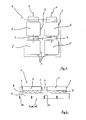
- FIG. 1 a Zu povertydecke 1 four connection modules 2, 2 ', 2 ", 2'", each having three connecting pieces 3.
- the connection modules 2, 2 “and 2 ', 2'” are each connected to one another by means of connecting channels 4, so that a respective supply air flow can flow between the connected connection modules 2, 2 "or 2 ', 2'".
- FIG. 1 illustrated by means of vertically aligned arrows 5.
- the connection modules 2, 2 ' are further connected to a supply air duct, not shown, and are supplied by this with a supply air, which is indicated by arrows 6.
- Each of the connection modules 2, 2 ', 2 ", 2'” has smaller dimensions, as a quarter of Zu povertydecke 1.
- FIG. 1 shown in a plan view Zu Kunststoffdecke 1 is in FIG. 2 shown in a vertical section.
- the individual connection modules 2, 2 ', 2 ", Z"' are arranged, whereby only two connection modules 2, 2 "are recognizable due to the way of representation, which are interconnected by means of the connection channel 4 as described above.
- the individual interconnected connection modules 2, 2 ', 2 ", 2'” each form an independent air inlet space
- the supply air ceiling 1 correspondingly has two air inlet spaces, a first consisting of the interconnected connection modules 2, 2 "and a second one Both air inlet spaces are separated from an air outlet space 7 in such a way by means of filter units 8 that the respectively supplied supply air flow can only reach the air outlet space 7 by being one of the filter units 8 This ensures that there is no unfiltered air in the air intake strittsraum 7 passes.
- the air outlet space 7 is designed as a continuous uniform space, so that all entering the air outlet space 7 incoming air streams can reach from any point within the air outlet space 7 to any other point in the air outlet space 7. This therefore has no separated area.
- the supply air streams flowing from the individual air inlet spaces through the filter elements 8 are combined and united in the continuous air outlet space 7. As a result, the supply air stream is homogenized.
- the supply air ceiling 1 has four individual laminarizers 10 over an entire width and length, so that a total of 16 laminarizers 10 form the air outlet surface 9 of the Zu Kunststoffdecke 1.
- the individual laminarizers 10, each having a frame 11 and a textile fabric 12, are fastened by means of bearing rails 13 in the Zu Kunststoffdecke 1.
- the laminarizers 10 ensure by their flow resistance for a uniform distribution and rectification of the outflow into the target space supply air.
- FIG. 3 An alternative arrangement of the laminarizers 10 is in a further embodiment, which in FIG. 3 is pictured, realized.
- This double-layered arrangement causes an outflow velocity of the supply air flow from the Zu povertydecke 1 is reduced in the target space with respect to an inner region 15 of the Zu povertydecke 1.
- laminarizers 10 of different types with regard to the textile fabric 12 used.
- An advantage of using identical laminarizers 10 is that there is neither a risk of confusion during assembly, nor a complex storage for different types of laminarizers 10 must be operated.
- the expert speaks of a so-called "differential flow”.
- the inner region 15 of the Zubuchdecke is set such that an outflow velocity of the supply air flow is increased in the target area in this inner region 15 relative to that outflow velocity in the outer region 14 of the Zubuchdecke 1.
- a relatively intensive ventilation for example, an operating table, which is arranged below the inner region 15 of the Zubuchdecke 1, compared to an environment of the operating table achieved.
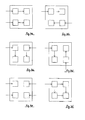
- FIGS. 4a show different connection types of the supply air ceiling 1 to one or more supply air ducts. These are in the FIGS. 4a pictured up to 4g.
- the connection type is off FIG. 4a already known from the first embodiment, which in FIG. 1 is shown.
- connection module 2 shows a separate connection of each connection module 2, 2 ', 2 ", 2'” to a separate supply air duct.
- the associated Zu povertydecke 1 has accordingly over four air inlet spaces, which are each formed only from a connection module 2, 2 ', 2 ", 2'".
- FIG. 4f illustrated Zu Kunststoffdecke This has only one point, is supplied to the supply air.
- the connected connection module 2 is connected to the two adjacent connection modules 2 ', 2 "analogously to the other connection modules 2', 2", 2 "'.
- all four connection modules 2, 2', 2", 2 ' are connected. "connected via a kind of" ring line "with each other, so that the air inlet space is formed in this example of all four connection modules 2, 2 ', 2", 2'".
Landscapes
- Engineering & Computer Science (AREA)
- Mechanical Engineering (AREA)
- Life Sciences & Earth Sciences (AREA)
- Combustion & Propulsion (AREA)
- General Engineering & Computer Science (AREA)
- Chemical & Material Sciences (AREA)
- Health & Medical Sciences (AREA)
- General Health & Medical Sciences (AREA)
- Biomedical Technology (AREA)
- Animal Behavior & Ethology (AREA)
- Surgery (AREA)
- Public Health (AREA)
- Veterinary Medicine (AREA)
- Wood Science & Technology (AREA)
- Zoology (AREA)
- Food Science & Technology (AREA)
- Forests & Forestry (AREA)
- Ventilation (AREA)
- Duct Arrangements (AREA)
- Filtering Of Dispersed Particles In Gases (AREA)
Applications Claiming Priority (1)
| Application Number | Priority Date | Filing Date | Title |
|---|---|---|---|
| DE102011050273A DE102011050273A1 (de) | 2011-05-11 | 2011-05-11 | Zuluftdecke |
Publications (1)
| Publication Number | Publication Date |
|---|---|
| EP2522924A2 true EP2522924A2 (fr) | 2012-11-14 |
Family
ID=46177232
Family Applications (1)
| Application Number | Title | Priority Date | Filing Date |
|---|---|---|---|
| EP12166756A Withdrawn EP2522924A2 (fr) | 2011-05-11 | 2012-05-04 | Plafond pour admission d'air |
Country Status (2)
| Country | Link |
|---|---|
| EP (1) | EP2522924A2 (fr) |
| DE (2) | DE102011050273A1 (fr) |
Cited By (2)
| Publication number | Priority date | Publication date | Assignee | Title |
|---|---|---|---|---|
| DE102014004922B3 (de) * | 2014-04-07 | 2015-03-12 | Innovations-Transfer Uphoff Gmbh &.Co.Kg | Laminarisatorpassagevorrichtung |
| DE102014004921B3 (de) * | 2014-04-07 | 2015-04-16 | Innovations-Transfer Uphoff Gmbh & Co. Kg | Reinraumbeleuchtungsvorrichtung |
Citations (1)
| Publication number | Priority date | Publication date | Assignee | Title |
|---|---|---|---|---|
| DE2717613A1 (de) | 1976-05-08 | 1977-11-10 | Howorth Air Eng Ltd | Geraet zur erzeugung einer zone sauberer luft |
Family Cites Families (3)
| Publication number | Priority date | Publication date | Assignee | Title |
|---|---|---|---|---|
| DE4014796A1 (de) * | 1990-05-09 | 1991-11-14 | Rheydt Kabelwerk Ag | Verfahren zur linearisierung der uebertragungsfunktion |
| DE29913020U1 (de) * | 1999-07-26 | 1999-12-09 | Weiss Klimatechnik GmbH, 35447 Reiskirchen | Zuluftdecke |
| DE202005004384U1 (de) * | 2004-03-16 | 2005-06-02 | M+W Zander Gebäudetechnik GmbH | Vorrichtung zur Belüftung eines Arbeitsplatzes |
-
2011
- 2011-05-11 DE DE102011050273A patent/DE102011050273A1/de not_active Ceased
- 2011-05-11 DE DE202011110896.5U patent/DE202011110896U1/de not_active Expired - Lifetime
-
2012
- 2012-05-04 EP EP12166756A patent/EP2522924A2/fr not_active Withdrawn
Patent Citations (1)
| Publication number | Priority date | Publication date | Assignee | Title |
|---|---|---|---|---|
| DE2717613A1 (de) | 1976-05-08 | 1977-11-10 | Howorth Air Eng Ltd | Geraet zur erzeugung einer zone sauberer luft |
Cited By (4)
| Publication number | Priority date | Publication date | Assignee | Title |
|---|---|---|---|---|
| DE102014004922B3 (de) * | 2014-04-07 | 2015-03-12 | Innovations-Transfer Uphoff Gmbh &.Co.Kg | Laminarisatorpassagevorrichtung |
| DE102014004921B3 (de) * | 2014-04-07 | 2015-04-16 | Innovations-Transfer Uphoff Gmbh & Co. Kg | Reinraumbeleuchtungsvorrichtung |
| EP2929864A1 (fr) | 2014-04-07 | 2015-10-14 | Innovations-Transfer Uphoff GmbH & Co. KG | Dispositif d'éclairage de salle blanche |
| EP2942575A1 (fr) | 2014-04-07 | 2015-11-11 | Innovations-Transfer Uphoff GmbH & Co. KG | Dispositif de passage de distributeur d'air |
Also Published As
| Publication number | Publication date |
|---|---|
| DE102011050273A1 (de) | 2012-11-15 |
| DE202011110896U1 (de) | 2017-02-13 |
Similar Documents
| Publication | Publication Date | Title |
|---|---|---|
| EP0497296B1 (fr) | Installation de filtre-ventilateur pour l'utilisation dans des salles blanches | |
| EP2534286B1 (fr) | Four d'oxydation | |
| DE29916321U1 (de) | Reinstlufteinrichtung für den Pharmazie-, Lebensmittel- und biotechnischen Bereich | |
| EP2820356B1 (fr) | Installation de ventilation de salles blanches | |
| WO2010026049A1 (fr) | Véhicule ferroviaire pouvant être commuté entre un mode hiver et un mode été | |
| DE202020103567U1 (de) | Behandlungsanlage | |
| DE202016106540U1 (de) | Luftauslass zum Temperieren eines Raumes | |
| DE102020122848A1 (de) | Luftführungs-Tafelelement | |
| EP3244934B1 (fr) | Système de décontamination | |
| EP2522924A2 (fr) | Plafond pour admission d'air | |
| DE69207056T2 (de) | Verfahren und Vorrichtung für die Belüftung eines Behandlungsraumes | |
| EP2161512B1 (fr) | Appareil d'aération décentralisé et installation d'aération dotée d'un tel appareil | |
| EP0410098B1 (fr) | Système d'espace en construction modulaire pour un climat spécial | |
| EP2601927A1 (fr) | Dispositif d'aération pour salles blanches et salle blanche avec un tel dispositif | |
| DE3634312C2 (fr) | ||
| DE4103026C1 (fr) | ||
| AT527063B1 (de) | Zuluftverteiler, Hallenschichtlüftungssystem und Verfahren zur Dimensionierung eines Hallenschichtlüftungssystems | |
| DE69105947T2 (de) | Lüftungsanlage. | |
| DE102012107542A1 (de) | Vorrichtung zur Aufteilung eines Luftstroms sowie damit ausgestattete Trocknungsanlage | |
| DE2932616A1 (de) | Spritzkabine | |
| DE20102737U1 (de) | Luftaustrittseinrichtung und zugehörige Klimatisierungsvorrichtung | |
| AT524615B1 (de) | Luftreinigungsvorrichtung | |
| WO2025140950A1 (fr) | Système de ventilation, appareil de purification et procédé de fourniture d'une zone propre au moyen d'un flux d'air | |
| DE2442378A1 (de) | Klimaanlage | |
| DE202015102781U1 (de) | Lüftungseinrichtung für Reinräume |
Legal Events
| Date | Code | Title | Description |
|---|---|---|---|
| PUAI | Public reference made under article 153(3) epc to a published international application that has entered the european phase |
Free format text: ORIGINAL CODE: 0009012 |
|
| AK | Designated contracting states |
Kind code of ref document: A2 Designated state(s): AL AT BE BG CH CY CZ DE DK EE ES FI FR GB GR HR HU IE IS IT LI LT LU LV MC MK MT NL NO PL PT RO RS SE SI SK SM TR |
|
| AX | Request for extension of the european patent |
Extension state: BA ME |
|
| RAP1 | Party data changed (applicant data changed or rights of an application transferred) |
Owner name: CAVERION DEUTSCHLAND GMBH |
|
| STAA | Information on the status of an ep patent application or granted ep patent |
Free format text: STATUS: THE APPLICATION IS DEEMED TO BE WITHDRAWN |
|
| 18D | Application deemed to be withdrawn |
Effective date: 20151201 |