EP2523066A2 - Terminal mobile - Google Patents
Terminal mobile Download PDFInfo
- Publication number
- EP2523066A2 EP2523066A2 EP12002321A EP12002321A EP2523066A2 EP 2523066 A2 EP2523066 A2 EP 2523066A2 EP 12002321 A EP12002321 A EP 12002321A EP 12002321 A EP12002321 A EP 12002321A EP 2523066 A2 EP2523066 A2 EP 2523066A2
- Authority
- EP
- European Patent Office
- Prior art keywords
- key body
- terminal
- window
- key
- light guide
- Prior art date
- Legal status (The legal status is an assumption and is not a legal conclusion. Google has not performed a legal analysis and makes no representation as to the accuracy of the status listed.)
- Granted
Links
Images


Classifications
-
- H—ELECTRICITY
- H04—ELECTRIC COMMUNICATION TECHNIQUE
- H04B—TRANSMISSION
- H04B1/00—Details of transmission systems, not covered by a single one of groups H04B3/00 - H04B13/00; Details of transmission systems not characterised by the medium used for transmission
- H04B1/38—Transceivers, i.e. devices in which transmitter and receiver form a structural unit and in which at least one part is used for functions of transmitting and receiving
-
- G—PHYSICS
- G06—COMPUTING OR CALCULATING; COUNTING
- G06F—ELECTRIC DIGITAL DATA PROCESSING
- G06F1/00—Details not covered by groups G06F3/00 - G06F13/00 and G06F21/00
- G06F1/16—Constructional details or arrangements
- G06F1/1613—Constructional details or arrangements for portable computers
- G06F1/1626—Constructional details or arrangements for portable computers with a single-body enclosure integrating a flat display, e.g. Personal Digital Assistants [PDAs]
-
- G—PHYSICS
- G06—COMPUTING OR CALCULATING; COUNTING
- G06F—ELECTRIC DIGITAL DATA PROCESSING
- G06F1/00—Details not covered by groups G06F3/00 - G06F13/00 and G06F21/00
- G06F1/16—Constructional details or arrangements
-
- G—PHYSICS
- G06—COMPUTING OR CALCULATING; COUNTING
- G06F—ELECTRIC DIGITAL DATA PROCESSING
- G06F1/00—Details not covered by groups G06F3/00 - G06F13/00 and G06F21/00
- G06F1/16—Constructional details or arrangements
- G06F1/1613—Constructional details or arrangements for portable computers
- G06F1/1633—Constructional details or arrangements of portable computers not specific to the type of enclosures covered by groups G06F1/1615 - G06F1/1626
- G06F1/1684—Constructional details or arrangements related to integrated I/O peripherals not covered by groups G06F1/1635 - G06F1/1675
-
- G—PHYSICS
- G06—COMPUTING OR CALCULATING; COUNTING
- G06F—ELECTRIC DIGITAL DATA PROCESSING
- G06F3/00—Input arrangements for transferring data to be processed into a form capable of being handled by the computer; Output arrangements for transferring data from processing unit to output unit, e.g. interface arrangements
- G06F3/01—Input arrangements or combined input and output arrangements for interaction between user and computer
- G06F3/02—Input arrangements using manually operated switches, e.g. using keyboards or dials
- G06F3/0202—Constructional details or processes of manufacture of the input device
-
- H—ELECTRICITY
- H04—ELECTRIC COMMUNICATION TECHNIQUE
- H04M—TELEPHONIC COMMUNICATION
- H04M1/00—Substation equipment, e.g. for use by subscribers
- H04M1/02—Constructional features of telephone sets
-
- H—ELECTRICITY
- H04—ELECTRIC COMMUNICATION TECHNIQUE
- H04M—TELEPHONIC COMMUNICATION
- H04M1/00—Substation equipment, e.g. for use by subscribers
- H04M1/02—Constructional features of telephone sets
- H04M1/23—Construction or mounting of dials or of equivalent devices; Means for facilitating the use thereof
-
- H—ELECTRICITY
- H01—ELECTRIC ELEMENTS
- H01H—ELECTRIC SWITCHES; RELAYS; SELECTORS; EMERGENCY PROTECTIVE DEVICES
- H01H2219/00—Legends
- H01H2219/036—Light emitting elements
- H01H2219/039—Selective or different modes of illumination
-
- H—ELECTRICITY
- H03—ELECTRONIC CIRCUITRY
- H03K—PULSE TECHNIQUE
- H03K2217/00—Indexing scheme related to electronic switching or gating, i.e. not by contact-making or -breaking covered by H03K17/00
- H03K2217/94—Indexing scheme related to electronic switching or gating, i.e. not by contact-making or -breaking covered by H03K17/00 characterised by the way in which the control signal is generated
- H03K2217/96—Touch switches
- H03K2217/9607—Capacitive touch switches
- H03K2217/960785—Capacitive touch switches with illumination
-
- H—ELECTRICITY
- H04—ELECTRIC COMMUNICATION TECHNIQUE
- H04M—TELEPHONIC COMMUNICATION
- H04M1/00—Substation equipment, e.g. for use by subscribers
- H04M1/02—Constructional features of telephone sets
- H04M1/0202—Portable telephone sets, e.g. cordless phones, mobile phones or bar type handsets
- H04M1/026—Details of the structure or mounting of specific components
- H04M1/0266—Details of the structure or mounting of specific components for a display module assembly
-
- H—ELECTRICITY
- H04—ELECTRIC COMMUNICATION TECHNIQUE
- H04M—TELEPHONIC COMMUNICATION
- H04M1/00—Substation equipment, e.g. for use by subscribers
- H04M1/02—Constructional features of telephone sets
- H04M1/22—Illumination; Arrangements for improving the visibility of characters on dials
-
- H—ELECTRICITY
- H04—ELECTRIC COMMUNICATION TECHNIQUE
- H04M—TELEPHONIC COMMUNICATION
- H04M2250/00—Details of telephonic subscriber devices
- H04M2250/22—Details of telephonic subscriber devices including a touch pad, a touch sensor or a touch detector
Definitions
- This disclosure relates to an input apparatus for a mobile terminal, and a configuration of a display unit thereof.
- a terminal can be allowed to capture still images or moving images, play music or video files, play games, receive broadcast and the like, so as to be implemented as an integrated multimedia player.
- Such terminals may be divided into mobile/portable terminals and stationary terminals according to their mobility.
- the mobile terminals can be easily carried and have one or more of functions such as supporting voice and video telephony calls, inputting and/or outputting information, storing data and the like.
- an aspect of the detailed description is to provide a mobile terminal having an appearance in a different shape from the existing shapes, namely, a mobile terminal having unique patterns on an outer surface of a case thereof.
- a mobile terminal including a window having patterns sensitive to user's touch inputs, a key region formed at one surface of the window, and a key body assembly disposed on the other surface of the window to be laminated on the key region, wherein the key body assembly has one surface equipped with at least one recess member or protrusion member, and the other surface equipped with a key body coupled to a light guide film.
- the key body assembly may further include electric diodes laminated on one surface of the light guide film to emit light to at least part of the key region in response to a touch input.
- a key mark printed layer having different patterns related to functions of the terminal may be located between the key body and the light guide film.
- the window may include a key mark printed layer having different patterns related to functions of the terminal.
- the key body may be divided into plurality, and the respective divided key bodies may have different patterns related to functions of the terminal.
- the key body may be made of a transparent or semi-transparent material.
- the key body and the window may be partially spaced apart from each other by a predetermined gap, and the key body assembly may further include a filler to fill the gap.
- the key body may have a first refractive index
- the window may have a second refractive index
- the second refractive index may be greater than the first refi-active index.
- a mobile terminal may be implemented to have unique patterns on its outer appearance, thereby arousing a distinguished attraction and a quality enhanced appearance.
- FIG. 1 is a front perspective view of a mobile terminal in accordance with one exemplary embodiment
- FIG. 2 is a rear perspective view of the mobile terminal
- FIG. 3 is a disassembled perspective view of the mobile terminal
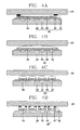
- FIGS. 4A to 4D are sectional views taken along the line IV-IV of FIG. 1 ;
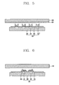
- FIG. 5 is a sectional view taken along the line IV-IV of FIG. 1 in relation to an exemplary variation
- FIG. 6 is a sectional view taken along the line V-V of FIG. 1 .
- FIG. 1 is a front perspective view of a mobile terminal 100 in accordance with one exemplary embodiment.
- a case (casing, housing, cover, etc.) forming an outer appearance of the mobile terminal 100 may be formed from a front case 111 and a rear case 121.
- a space formed by the front case 111 and the rear case 121 may accommodate various components therein.
- At least one intermediate case may further be disposed between the front case 111 and the rear case 121.
- Such cases may be formed by injection-molded synthetic resin, or may be formed using a metallic material such as stainless steel (STS) or titanium (Ti).
- the front case 111 is shown having a display unit 113, a first audio output module 114, a first image input unit 115, a first manipulation unit 116, an audio input unit 117 and the like.
- the display unit 113 may include a display module 141 (see FIG. 3 ), such as a Liquid Crystal Display (LCD) module, an Organic Light-Emitting Diode (OLED) module and the like to display visible information.
- the display unit 113 may be implemented as a touch screen so as to allow inputting of information by a user's touch.
- the first audio output module 114 may include a receiver, a speaker or the like.
- the first image input unit 115 may be a camera module for capturing images or video of the user and the like.
- the first manipulation unit 116 may be manipulated to allow inputting of commands for controlling operations of the mobile terminal 100, and be a key region formed to receive a user's touch input given on a window.
- the audio input unit 117 may be implemented, for example, as a type of microphone for receiving voice or other sounds input by the user.
- the rear case 121 mounted to the rear surface of the mobile terminal 100 may be provided with a second manipulation unit 123, an interface 124, a power supply unit 125 and the like.
- the second manipulation unit 123 may be installed at a side surface of the rear case 121.
- the first and manipulation units 116 and 123 may be referred to as a manipulating portion.
- Such manipulating portion can employ any tactile manner that a user can touch or tap for manipulation.
- the manipulating portion may be implemented as a dome switch, a touchpad or the like by which a user can input commands or information in a pushing or touching manner.
- the manipulating portion may be implemented as a wheel or a jog which rotates keys or a joystick.
- the first manipulation unit 116 is configured to input commands such as START, END or the like, and the second manipulation unit 123 can be worked as a hot key which performs a specific function, such as activating of the first image input unit 115, as well as a scroll function.
- the first and second manipulation units 116 and 123 inputting of telephone numbers or text messages may be executed using a touch screen disposed on the display unit 113.
- the interface 124 may serve as a path for allowing data exchange between the mobile terminal and an external device.
- the interface 124 may be at least one of wired/wireless earphone ports, ports for short-range communication (e.g., IrDA, Bluetooth, WLAN, etc.), power supply terminals for power supply to the mobile terminal and the like.
- the interface 124 may be a card socket for coupling to external cards, such as a Subscriber Identity Module (SIM), a User Identity Module (UIM), a memory card for storage of information and the like.
- SIM Subscriber Identity Module
- UIM User Identity Module
- a power supply unit 125 may be provided at the rear case 121 to supply power to at least one component of the mobile terminal 100.
- the power supply unit 125 may include a rechargeable battery for power supply.
- the battery may be detachably coupled for charging or the like.
- FIG. 2 is a rear perspective view of the mobile terminal 100 of FIG. 1 .
- the rear case 121 is shown having a second image input unit 127, a second audio output module 130, a broadcast signal receiving antenna 131 and the like.
- the second image input unit 127 faces a direction which is opposite to a direction faced by the first image input unit 115 (see FIG. 1 ), and may have different pixels from those of the first image input unit 115.
- the first image input unit 115 may operate with relatively lower pixels (lower resolution).
- the first image input unit 115 may be useful when a user can capture his face and send it to another party during a video call or the like.
- the second image input unit 127 may operate with relatively higher pixels (higher resolution) such that it can be useful for a user to obtain higher quality pictures for later use.
- a flash 128 and a mirror 129 may additionally be disposed adjacent to the second image input unit 127.
- the flash 129 operates in conjunction with the second image input unit 128 when taking a picture using the second image input unit 127.
- the mirror 129 can cooperate with the second image input unit 127 to allow a user to photograph himself in a self-portrait mode.
- the second audio output module 130 can cooperate with the first audio output module 114 (see FIG. 1 ) to provide stereo output. Also, the audio output module 130 may be configured to operate as a speakerphone.
- a broadcast signal receiving antenna 131 may be disposed at one side of the rear case 121 in addition to an antenna for communications.
- the antenna 131 may be drawn out of the rear case 121.
- the first manipulation unit 116 or the like is disposed at the front case 111 and the second manipulation unit 123 or the like is disposed at the rear case 121; however, the present disclosure may not be limited to the configuration.
- the second manipulation unit 123 may be disposed at the front case 111 in the vicinity of the first manipulation unit 116.
- the first image input unit 115 can be implemented to be rotatable so as to rotate up to a direction which the second image input unit 127 faces.
- FIG. 3 is a disassembled perspective view of the mobile terminal 100.
- a window 140 may be coupled to cover one surface of the front case 111.
- the window 140 may cover the one surface of the display module 141 such that visual information output on the display module 141 can be recognized from the exterior.
- the display module 141 and the window 140 may implement the display unit 113 (see FIG. 1 ).
- the window 140 may be configured to be sensitive to user's touch inputs, and allowed for inputting of information (commands, signals, etc.).
- the window 140 may have an area corresponding to the display module 141, and be made of a transparent material.
- the window 140 may have an opaque region having no transparency or very low transparency. For example, a surface processing may be executed for the edges of the window 140 such that light cannot be transmitted therethrough.
- the window 140 may generally be formed of a transparent or semi-transparent material.
- partial regions 140b, 140c of the window 140 are formed of the semi-transparent, the other regions of the window 140 are formed of the transparent material, or vice versa.
- key bodies 181 or a pattern portion located beneath low surfaces of the first regions 140b and a lower surface of the second region 140c may achieve a three-dimensional effect or improved visibility, and acquire distinguished beauty.
- the window 140 adjacent to a bezel and a key region occupied by the first manipulation unit 116 may be formed opaque or semi-transparent, while the first region 140b may be formed transparent so as to allow for visible recognition of the key body 181 formed beneath the first region 140b, thereby providing user convenience and unique attraction of the terminal.
- a manipulation pad corresponding to the first manipulation unit 116 may be formed at the front case 111.
- the manipulation pad may be subject to user's touching or pressing.
- the manipulation pad may be formed as a manipulation region on a part of the window 140.
- the front case 111 may further include a sound hole 114b, a window hole 112b and an image window.
- the sound hole 114b may be formed in alignment with the audio output module 114 (see FIG. 1 ) to allow for outputting of sounds, for example, ring tone, music and the like, to the outside of the mobile terminal.
- the window hole 112b may be formed in alignment with the display unit 113.
- a transparent (light-transmittable) window may also be located on a camera module 115b formed in alignment with the first image input unit 115 (see FIG. 1 ).
- the rear case 112 may include a circuit board 170, a display module 141, a speaker module 114a, a camera module, a switch and the like.
- the circuit board 170 may be configured as one example of a controller for controlling various functions of the mobile terminal 100.
- the circuit board 170 may detect electrical changes, for example, changes in capacitance or the quantity of electric charges, which occur within the window 140 as a user touches the window 140.
- An electrode may be located inside the window 140.
- the electrode may be a conductive pattern.
- the electrode may be charged with charges.
- the quantity of electric charges may change.
- a conductive body for example, a fmger touches a window
- the quantity of charges charged in the electrode may change, which can be understood that the capacitance between the fmger and the electrode changes.
- the electrode of the window 140 may be electrically connected to a controller, for example, the circuit board 170 for detecting the changes in the quantity of charges.
- a controller for example, the circuit board 170 for detecting the changes in the quantity of charges.
- a flexible circuit board may be connected to the circuit board 170 through a hole (not shown). With the change in the quantity of charges detected, the circuit board 170 may change a state of at least one of functions related to the mobile terminal 100.
- FIGS. 4A to 4D are sectional views taken along the line IV-IV of FIG. 1 .
- FIG. 5 is a sectional view taken along the line IV-IV of FIG. 1 in relation to an exemplary variation.
- the first manipulation unit 116 (see FIG. 1 ) is formed on one surface of the window 140 (hereinafter, the first manipulation unit 116 is referred to as a key region for reception of touch inputs).
- the key region 116 When the key region 116 is touched, the touched region may be detected and a preset signal with respect to the touch-detected region may be transferred to a controller so as to allow a specific function of the terminal to be performed.
- a key body assembly 180, 180', 180", 180"', 180”” may be formed beneath the window 140. That is, the window 140 and the key region 116 may be stacked on the key body assembly 180, 180', 180", 180"', 180"".
- the key body assembly 180, 180', 180", 180"' may include a key body 181, 181', 181", 181"' overall having a concave or convex shape.
- the key body 181, 181', 181", 181"' may be divided into plurality.
- the thickness of the key body 181 continuously changes from one end to the other, accordingly, light transmitted from the lower end to the upper end of the key body assembly 180 may be diffused or refracted, thereby giving the key body assembly 180 a unique three-dimensional effect.
- the key body 181 may be formed to have a portion with a different refractive index from other portions. Accordingly, a light path may differ at each portion due to the difference of thickness or refractive index, so the key body assembly 180 may obtain a unique three-dimensional effect.
- the key body 181 may be divided into plurality, and each divided key body 181 may have a different pattern related to a function of the terminal.
- the pattern is a type of key mark.
- Each pattern as shown in FIGS. 1 to 3 , may have a specific shape, such as square, house, arrow indicating the rear, magnifying glass or the like, so as to be associated with a function of the terminal, like menu, home, rewind, search or the like.
- the key region 116 is provided with key marks having different patterns, and predetermined functions of the terminal are executed when a user touches a region where those key marks are disposed.
- the key body 181 may be made of a transparent or semi-transparent material. Also, the key body 181 may be formed by UV molding, silicon molding, or made of epoxy resin.
- the key body 181 may be laminated (stacked) on a light guide film 182.
- the light guide film 182 may serve as a path of light emitted from lower electric diodes 184.
- the electric diode 184 may be a light emitting diode (LED) having high efficiency in power consumption.
- a lower layer 183 of the light guide film 182 may be a circuit board or a display module.
- a key mark printed layer 150 having different patterns related to functions of the terminal may be located between the key body 181"" and the light guide film 182.
- the key mark printed layer 150 may alternatively be formed on the window 140.
- each of key marks disposed on the key mark printed layer 150 may have a specific shape, such as square, house, arrow indicating the rear, magnifying glass or the like, so as to be associated with a function of the terminal, like menu, home, rewind, search or the like.
- users can guess, viewing those key marks, that they can execute a desired function of the terminal by pressing or touching the corresponding key region 116.
- the key region 116 may be divided into plurality.
- the plurality of key regions 116 may be radiated by the lower electric diodes 184 and controlled to operate independent of one another.
- the divided key regions 116 are visible with different brightness or different color of light, thereby providing user convenience in use and distinguished attraction to the terminal.
- the key bodies may have an improved three-dimensional effect by making the key body 181 and the window 140 laminated on the key body 181 have different refractive indexes.
- a refi-active index of a glass substrate increases if the glass substrate contains Nb 2 O 5 BaO and TiO 2 .
- the glass substrate has a refractive index over 1.8.
- the refractive index of the key body 181 is typically less than 1.5.
- the refractive index of the window 140 may be set higher than that of the key body 181, visibilities of the key marks can be improved and the three-dimensional effect of the key body 181 can be further enhanced.
- the key body 181 and the window 140 may be formed to be partially spaced from each other by a predetermined gap.
- a filler 185 for filling the gap may be disposed so as to elastically support the window 140 when the window 140 is pressed and prevent moisture permeation into the gap.
- the key body 181 and the window 140 corresponding to the key region 116 below which the key body 181 is laminated may be configured to partially have different colors.
- the key body 181 and the window 140 may be formed with different colors alternately or sequentially present in a thickness direction or a width direction.
- a part of one surface of the key body may be recessed and provided with a dark or light blue color and a portion wrapping the recessed part may be provided with a light or dark blue color, thereby giving a three-dimensional effect to the recessed part.
- the key body or the window may be formed with a plurality of colors, which consecutively change in the thickness direction or the width direction, or create a gradation effect showing a gradually darkening or lightening change.
- the key body 181 can exhibit more improved three-dimensional effect and visibility.
- the first region 140b may be formed to have a different refractive index or transparency from the adjacent window. Accordingly, the key body 181 formed beneath the first region 140b may appear larger or smaller. Also, the edges of the window in the vicinity of a bezel may be formed opaque or semi-transparent, and only the first region 140b may be formed transparent, thereby improving visibility of the key body 181 formed beneath the first region 140b or enhancing the three-dimensional effect of a recess member or protrusion member of the key body 181.
- FIG. 6 is a sectional view taken along the line V - V of FIG. 1 .
- the logo unit 190 may be located between the window 140 and the terminal body, and formed by laminating a pattern portion 191 and the like.
- the aforementioned key mark corresponds to the pattern portion 191, and may include one of character, number, symbol or a pattern defining a logo.
- the pattern portion 191 may have a portion protruded or recessed as compared with other portions. Also, the pattern portion 191 may overall have concave or convex shape. Here, the thickness of the pattern portion 191 continuously changes from one end to the other, accordingly, light transmitted from the lower end to the upper end of the pattern portion 191 may be diffused or refracted, thereby giving the pattern portion 191 a unique three-dimensional effect.
- the pattern portion 191 may be formed to have a portion with a different refractive index from other portions. Accordingly, a light path may differ at each portion due to the difference of thickness or refractive index, so the pattern portion 191 may have a unique three-dimensional effect.
- the pattern portion 191 may be made of a transparent or semi-transparent material. Also, the pattern portion 191 may be formed by UV molding, silicon molding, or made of epoxy resin.
- the pattern portion 191 may be stacked on the light guide film 192.
- the light guide film 192 may serve as a path of light emitted from a lower electric diode 194.
- the electric diode 194 emits light, at least a part of the pattern portion 191 can be radiated.
- the electric diode 194 may be a light emitting diode (LED) having high efficiency in power consumption.
- a lower layer 193 of the light guide film 192 may be a circuit board or a display module.
- a printed layer 195 which includes one of character, number, symbol or a pattern defining a logo, may be located between the pattern portion 191 and the light guide film 192.
- the printed layer 195 may alternatively be formed on the window 140 similar to the arrangement of the printed layer 150 as shown in FIG. 5 .
- the pattern portion 191 may be divided into plurality, and each divided pattern portion 191 may include one of character, number, symbol or a pattern defining a logo.
- the light guide film 192, the pattern portion 191 and the window 140 may have different refractive indexes or at least two of them may have different refractive indexes, thereby improving visibility of the pattern portion 191 and further enhancing the three-dimensional effect of the pattern portion 191.
- the pattern portion 191 and the window 140 may be formed to be partially spaced from each other by a predetermined gap.
- a filler may be disposed to fill the gap so as to elastically support the window 140 when the window 140 is pressed and prevent moisture permeation into the gap.
- the pattern portion 191 and the window 140 below which the pattern portion 191 is laminated may be configured to partially have different colors.
- the pattern portion 191 and the window 140 may be formed with different colors, which are present alternately or sequentially in a thickness direction or a width direction.
- a part of one surface of the pattern portion may be recessed and provided with a dark or light blue color and a portion wrapping the recessed part may be provided with a light or dark blue color, thereby giving a three-dimensional effect to the recessed part.
- the pattern portion 191 or the window 140 may be formed with a plurality of colors, which consecutively change in the thickness direction or the width direction, or create a gradation effect showing a gradually darkening or lightening change.
- the key body 181 can exhibit more improved three-dimensional effect and visibility.
Landscapes
- Engineering & Computer Science (AREA)
- Theoretical Computer Science (AREA)
- General Engineering & Computer Science (AREA)
- Human Computer Interaction (AREA)
- Physics & Mathematics (AREA)
- General Physics & Mathematics (AREA)
- Computer Hardware Design (AREA)
- Signal Processing (AREA)
- Computer Networks & Wireless Communication (AREA)
- Telephone Set Structure (AREA)
- Push-Button Switches (AREA)
- Input From Keyboards Or The Like (AREA)
Applications Claiming Priority (1)
| Application Number | Priority Date | Filing Date | Title |
|---|---|---|---|
| KR1020110044170A KR101832954B1 (ko) | 2011-05-11 | 2011-05-11 | 이동 단말기 |
Publications (3)
| Publication Number | Publication Date |
|---|---|
| EP2523066A2 true EP2523066A2 (fr) | 2012-11-14 |
| EP2523066A3 EP2523066A3 (fr) | 2014-11-26 |
| EP2523066B1 EP2523066B1 (fr) | 2016-12-21 |
Family
ID=45976610
Family Applications (1)
| Application Number | Title | Priority Date | Filing Date |
|---|---|---|---|
| EP12002321.3A Not-in-force EP2523066B1 (fr) | 2011-05-11 | 2012-03-30 | Terminal mobile |
Country Status (4)
| Country | Link |
|---|---|
| US (1) | US9285829B2 (fr) |
| EP (1) | EP2523066B1 (fr) |
| KR (1) | KR101832954B1 (fr) |
| CN (1) | CN102778929B (fr) |
Cited By (1)
| Publication number | Priority date | Publication date | Assignee | Title |
|---|---|---|---|---|
| EP2781994A3 (fr) * | 2013-03-21 | 2014-11-26 | HTC Corporation | Module tactile et appareil électronique |
Families Citing this family (9)
| Publication number | Priority date | Publication date | Assignee | Title |
|---|---|---|---|---|
| US20140055369A1 (en) * | 2012-08-22 | 2014-02-27 | Qualcomm Innovation Center, Inc. | Single-gesture mobile computing device operations |
| CN103019439B (zh) * | 2012-11-15 | 2017-03-01 | 福州华映视讯有限公司 | 触控屏幕与触控按键之整合系统 |
| CN103090316A (zh) * | 2013-02-25 | 2013-05-08 | 上海华勤通讯技术有限公司 | 触摸按键导光结构 |
| CN103279221A (zh) * | 2013-05-21 | 2013-09-04 | 北京小米科技有限责任公司 | 徽标组件、控制方法、控制器和电子设备 |
| KR20150084600A (ko) * | 2014-01-14 | 2015-07-22 | 엘지전자 주식회사 | 이동 단말기 |
| US20150227167A1 (en) * | 2014-02-10 | 2015-08-13 | Ming Yi CHIANG | Back cover assembly of electronic mobile device capable of controlling light emission effect |
| USD892780S1 (en) * | 2018-01-12 | 2020-08-11 | Samsung Electronics Co., Ltd. | Mobile phone |
| USD892781S1 (en) | 2018-01-12 | 2020-08-11 | Samsung Electronics Co., Ltd. | Mobile phone |
| US11175700B1 (en) | 2020-05-14 | 2021-11-16 | Apple Inc. | Electronic devices with adjustable-appearance housing structures |
Family Cites Families (20)
| Publication number | Priority date | Publication date | Assignee | Title |
|---|---|---|---|---|
| JP3862422B2 (ja) * | 1998-07-10 | 2006-12-27 | キヤノン株式会社 | 画像読取装置 |
| US7417624B2 (en) * | 2003-02-14 | 2008-08-26 | Duff Michael J | Zero-force key activation keyboard with dynamic individual key illumination |
| GB0306337D0 (en) | 2003-03-20 | 2003-04-23 | Global Display Solutions Ltd | Improvements to a display screen structure |
| US7223004B2 (en) * | 2003-04-18 | 2007-05-29 | Hon Hai Precision Ind. Co., Ltd. | Light guide plate with narrowed center and surface light source device incorporating same |
| US7196693B2 (en) * | 2003-12-12 | 2007-03-27 | Compal Electronics, Inc. | Lighting keyboard and lighting module thereof |
| US7113342B2 (en) * | 2005-02-24 | 2006-09-26 | Pong & Huang International Co., Ltd. | Composite structure for light diffusion |
| JP4716956B2 (ja) * | 2005-08-30 | 2011-07-06 | エルジー電子株式會社 | タッチキーアセンブリ及びこれを備えた移動通信端末機 |
| US8698752B2 (en) * | 2005-11-10 | 2014-04-15 | Id8 Group R2 Studios, Inc. | Multi-functional control interface |
| JP2007311325A (ja) * | 2006-04-17 | 2007-11-29 | Citizen Electronics Co Ltd | 導光板及びその製造方法とその導光板を用いたバックライトユニット |
| US7830368B2 (en) * | 2006-06-06 | 2010-11-09 | 3M Innovative Properties Company | Keypad with virtual image |
| WO2007146634A2 (fr) | 2006-06-06 | 2007-12-21 | 3M Innovative Properties Company | Pavé numérique à image virtuelle |
| US20080007964A1 (en) * | 2006-07-05 | 2008-01-10 | Tai-Yen Lin | Light guiding structure |
| KR100853518B1 (ko) * | 2007-01-09 | 2008-08-21 | 주식회사 옵틱스 | 다기능성 광학 필름, 이를 채용한 면광원장치와액정표시소자 |
| WO2009032721A1 (fr) * | 2007-09-06 | 2009-03-12 | 3M Innovative Properties Company | Guide de lumière avec flexibilité et durabilité |
| CN101424752A (zh) * | 2007-10-31 | 2009-05-06 | 富士迈半导体精密工业(上海)有限公司 | 光学透镜及光源模组 |
| TWI406551B (zh) | 2007-11-06 | 2013-08-21 | Lg Electronics Inc | 行動式終端機 |
| TWM335733U (en) * | 2008-01-22 | 2008-07-01 | Ichia Tech Inc | Key pressing structure with 3-dimension pattern |
| KR20110021898A (ko) * | 2008-06-23 | 2011-03-04 | 소니 주식회사 | 면 광원 장치 및 표시 장치 |
| US20110199322A1 (en) * | 2010-02-15 | 2011-08-18 | Research In Motion Limited | Graphical user interfaces for devices that present media content |
| CN102243544B (zh) * | 2010-05-12 | 2013-08-14 | 群康科技(深圳)有限公司 | 触控屏、触控屏的制造方法及触控显示装置 |
-
2011
- 2011-05-11 KR KR1020110044170A patent/KR101832954B1/ko not_active Expired - Fee Related
-
2012
- 2012-02-21 US US13/401,587 patent/US9285829B2/en not_active Expired - Fee Related
- 2012-03-21 CN CN201210076413.9A patent/CN102778929B/zh not_active Expired - Fee Related
- 2012-03-30 EP EP12002321.3A patent/EP2523066B1/fr not_active Not-in-force
Non-Patent Citations (1)
| Title |
|---|
| None |
Cited By (1)
| Publication number | Priority date | Publication date | Assignee | Title |
|---|---|---|---|---|
| EP2781994A3 (fr) * | 2013-03-21 | 2014-11-26 | HTC Corporation | Module tactile et appareil électronique |
Also Published As
| Publication number | Publication date |
|---|---|
| EP2523066B1 (fr) | 2016-12-21 |
| CN102778929A (zh) | 2012-11-14 |
| KR20120126415A (ko) | 2012-11-21 |
| EP2523066A3 (fr) | 2014-11-26 |
| KR101832954B1 (ko) | 2018-04-13 |
| US9285829B2 (en) | 2016-03-15 |
| CN102778929B (zh) | 2017-05-03 |
| US20120287060A1 (en) | 2012-11-15 |
Similar Documents
| Publication | Publication Date | Title |
|---|---|---|
| US9285829B2 (en) | Mobile terminal | |
| EP2541880B1 (fr) | Terminal mobile | |
| CN104811511B (zh) | 移动终端 | |
| RU2399085C2 (ru) | Мобильный терминал | |
| US8527020B2 (en) | Mobile terminal | |
| US8095180B2 (en) | Mobile terminal | |
| US8903459B2 (en) | Connecting terminal for a battery of a mobile terminal | |
| KR20090132014A (ko) | 휴대 단말기 | |
| US9794382B2 (en) | Mobile terminal | |
| US8902499B2 (en) | Display module and mobile terminal having the same | |
| CN107211054A (zh) | 终端及电子装置 | |
| KR20130087874A (ko) | 이동 단말기 및 이의 제조 방법 | |
| KR101772078B1 (ko) | 이동 단말기 | |
| KR101392916B1 (ko) | 휴대 단말기 | |
| KR101960513B1 (ko) | 이동 단말기 | |
| KR101922006B1 (ko) | 이동 단말기 | |
| KR101604749B1 (ko) | 휴대 단말기 및 휴대 단말기용 케이스의 제조방법 | |
| KR101910381B1 (ko) | 이동 단말기 | |
| KR20090076109A (ko) | 휴대 단말기 | |
| KR101789536B1 (ko) | 이동 단말기 | |
| KR20100039740A (ko) | 디스플레이 어셈블리 및 그를 구비하는 휴대 단말기 | |
| KR20100129029A (ko) | 터치 입력 유닛 및 그를 구비하는 휴대용 단말기 | |
| TW200950461A (en) | Portable electric apparatus |
Legal Events
| Date | Code | Title | Description |
|---|---|---|---|
| PUAI | Public reference made under article 153(3) epc to a published international application that has entered the european phase |
Free format text: ORIGINAL CODE: 0009012 |
|
| AK | Designated contracting states |
Kind code of ref document: A2 Designated state(s): AL AT BE BG CH CY CZ DE DK EE ES FI FR GB GR HR HU IE IS IT LI LT LU LV MC MK MT NL NO PL PT RO RS SE SI SK SM TR |
|
| AX | Request for extension of the european patent |
Extension state: BA ME |
|
| PUAL | Search report despatched |
Free format text: ORIGINAL CODE: 0009013 |
|
| AK | Designated contracting states |
Kind code of ref document: A3 Designated state(s): AL AT BE BG CH CY CZ DE DK EE ES FI FR GB GR HR HU IE IS IT LI LT LU LV MC MK MT NL NO PL PT RO RS SE SI SK SM TR |
|
| AX | Request for extension of the european patent |
Extension state: BA ME |
|
| RIC1 | Information provided on ipc code assigned before grant |
Ipc: G06F 3/02 20060101ALI20141021BHEP Ipc: G06F 1/16 20060101AFI20141021BHEP |
|
| 17P | Request for examination filed |
Effective date: 20150225 |
|
| RBV | Designated contracting states (corrected) |
Designated state(s): AL AT BE BG CH CY CZ DE DK EE ES FI FR GB GR HR HU IE IS IT LI LT LU LV MC MK MT NL NO PL PT RO RS SE SI SK SM TR |
|
| 17Q | First examination report despatched |
Effective date: 20151130 |
|
| GRAP | Despatch of communication of intention to grant a patent |
Free format text: ORIGINAL CODE: EPIDOSNIGR1 |
|
| RIC1 | Information provided on ipc code assigned before grant |
Ipc: H04M 1/22 20060101ALN20160623BHEP Ipc: G06F 1/16 20060101AFI20160623BHEP Ipc: G06F 3/02 20060101ALI20160623BHEP Ipc: H04M 1/02 20060101ALN20160623BHEP Ipc: H04M 1/23 20060101ALN20160623BHEP |
|
| RIC1 | Information provided on ipc code assigned before grant |
Ipc: H04M 1/22 20060101ALN20160629BHEP Ipc: H04M 1/23 20060101ALN20160629BHEP Ipc: G06F 3/02 20060101ALI20160629BHEP Ipc: G06F 1/16 20060101AFI20160629BHEP Ipc: H04M 1/02 20060101ALN20160629BHEP |
|
| INTG | Intention to grant announced |
Effective date: 20160711 |
|
| GRAS | Grant fee paid |
Free format text: ORIGINAL CODE: EPIDOSNIGR3 |
|
| GRAA | (expected) grant |
Free format text: ORIGINAL CODE: 0009210 |
|
| AK | Designated contracting states |
Kind code of ref document: B1 Designated state(s): AL AT BE BG CH CY CZ DE DK EE ES FI FR GB GR HR HU IE IS IT LI LT LU LV MC MK MT NL NO PL PT RO RS SE SI SK SM TR |
|
| REG | Reference to a national code |
Ref country code: GB Ref legal event code: FG4D |
|
| RIN1 | Information on inventor provided before grant (corrected) |
Inventor name: PARK, BYUNGDUCK |
|
| REG | Reference to a national code |
Ref country code: CH Ref legal event code: EP |
|
| REG | Reference to a national code |
Ref country code: IE Ref legal event code: FG4D |
|
| REG | Reference to a national code |
Ref country code: AT Ref legal event code: REF Ref document number: 856014 Country of ref document: AT Kind code of ref document: T Effective date: 20170115 |
|
| REG | Reference to a national code |
Ref country code: DE Ref legal event code: R096 Ref document number: 602012026763 Country of ref document: DE |
|
| PG25 | Lapsed in a contracting state [announced via postgrant information from national office to epo] |
Ref country code: LV Free format text: LAPSE BECAUSE OF FAILURE TO SUBMIT A TRANSLATION OF THE DESCRIPTION OR TO PAY THE FEE WITHIN THE PRESCRIBED TIME-LIMIT Effective date: 20161221 |
|
| REG | Reference to a national code |
Ref country code: LT Ref legal event code: MG4D |
|
| REG | Reference to a national code |
Ref country code: NL Ref legal event code: MP Effective date: 20161221 |
|
| PG25 | Lapsed in a contracting state [announced via postgrant information from national office to epo] |
Ref country code: SE Free format text: LAPSE BECAUSE OF FAILURE TO SUBMIT A TRANSLATION OF THE DESCRIPTION OR TO PAY THE FEE WITHIN THE PRESCRIBED TIME-LIMIT Effective date: 20161221 Ref country code: LT Free format text: LAPSE BECAUSE OF FAILURE TO SUBMIT A TRANSLATION OF THE DESCRIPTION OR TO PAY THE FEE WITHIN THE PRESCRIBED TIME-LIMIT Effective date: 20161221 Ref country code: NO Free format text: LAPSE BECAUSE OF FAILURE TO SUBMIT A TRANSLATION OF THE DESCRIPTION OR TO PAY THE FEE WITHIN THE PRESCRIBED TIME-LIMIT Effective date: 20170321 Ref country code: GR Free format text: LAPSE BECAUSE OF FAILURE TO SUBMIT A TRANSLATION OF THE DESCRIPTION OR TO PAY THE FEE WITHIN THE PRESCRIBED TIME-LIMIT Effective date: 20170322 |
|
| REG | Reference to a national code |
Ref country code: AT Ref legal event code: MK05 Ref document number: 856014 Country of ref document: AT Kind code of ref document: T Effective date: 20161221 |
|
| PG25 | Lapsed in a contracting state [announced via postgrant information from national office to epo] |
Ref country code: FI Free format text: LAPSE BECAUSE OF FAILURE TO SUBMIT A TRANSLATION OF THE DESCRIPTION OR TO PAY THE FEE WITHIN THE PRESCRIBED TIME-LIMIT Effective date: 20161221 Ref country code: HR Free format text: LAPSE BECAUSE OF FAILURE TO SUBMIT A TRANSLATION OF THE DESCRIPTION OR TO PAY THE FEE WITHIN THE PRESCRIBED TIME-LIMIT Effective date: 20161221 Ref country code: RS Free format text: LAPSE BECAUSE OF FAILURE TO SUBMIT A TRANSLATION OF THE DESCRIPTION OR TO PAY THE FEE WITHIN THE PRESCRIBED TIME-LIMIT Effective date: 20161221 |
|
| PG25 | Lapsed in a contracting state [announced via postgrant information from national office to epo] |
Ref country code: NL Free format text: LAPSE BECAUSE OF FAILURE TO SUBMIT A TRANSLATION OF THE DESCRIPTION OR TO PAY THE FEE WITHIN THE PRESCRIBED TIME-LIMIT Effective date: 20161221 |
|
| PG25 | Lapsed in a contracting state [announced via postgrant information from national office to epo] |
Ref country code: IS Free format text: LAPSE BECAUSE OF FAILURE TO SUBMIT A TRANSLATION OF THE DESCRIPTION OR TO PAY THE FEE WITHIN THE PRESCRIBED TIME-LIMIT Effective date: 20170421 Ref country code: RO Free format text: LAPSE BECAUSE OF FAILURE TO SUBMIT A TRANSLATION OF THE DESCRIPTION OR TO PAY THE FEE WITHIN THE PRESCRIBED TIME-LIMIT Effective date: 20161221 Ref country code: EE Free format text: LAPSE BECAUSE OF FAILURE TO SUBMIT A TRANSLATION OF THE DESCRIPTION OR TO PAY THE FEE WITHIN THE PRESCRIBED TIME-LIMIT Effective date: 20161221 Ref country code: CZ Free format text: LAPSE BECAUSE OF FAILURE TO SUBMIT A TRANSLATION OF THE DESCRIPTION OR TO PAY THE FEE WITHIN THE PRESCRIBED TIME-LIMIT Effective date: 20161221 Ref country code: SK Free format text: LAPSE BECAUSE OF FAILURE TO SUBMIT A TRANSLATION OF THE DESCRIPTION OR TO PAY THE FEE WITHIN THE PRESCRIBED TIME-LIMIT Effective date: 20161221 |
|
| PG25 | Lapsed in a contracting state [announced via postgrant information from national office to epo] |
Ref country code: BE Free format text: LAPSE BECAUSE OF FAILURE TO SUBMIT A TRANSLATION OF THE DESCRIPTION OR TO PAY THE FEE WITHIN THE PRESCRIBED TIME-LIMIT Effective date: 20161221 Ref country code: AT Free format text: LAPSE BECAUSE OF FAILURE TO SUBMIT A TRANSLATION OF THE DESCRIPTION OR TO PAY THE FEE WITHIN THE PRESCRIBED TIME-LIMIT Effective date: 20161221 Ref country code: IT Free format text: LAPSE BECAUSE OF FAILURE TO SUBMIT A TRANSLATION OF THE DESCRIPTION OR TO PAY THE FEE WITHIN THE PRESCRIBED TIME-LIMIT Effective date: 20161221 Ref country code: PT Free format text: LAPSE BECAUSE OF FAILURE TO SUBMIT A TRANSLATION OF THE DESCRIPTION OR TO PAY THE FEE WITHIN THE PRESCRIBED TIME-LIMIT Effective date: 20170421 Ref country code: ES Free format text: LAPSE BECAUSE OF FAILURE TO SUBMIT A TRANSLATION OF THE DESCRIPTION OR TO PAY THE FEE WITHIN THE PRESCRIBED TIME-LIMIT Effective date: 20161221 Ref country code: BG Free format text: LAPSE BECAUSE OF FAILURE TO SUBMIT A TRANSLATION OF THE DESCRIPTION OR TO PAY THE FEE WITHIN THE PRESCRIBED TIME-LIMIT Effective date: 20170321 Ref country code: PL Free format text: LAPSE BECAUSE OF FAILURE TO SUBMIT A TRANSLATION OF THE DESCRIPTION OR TO PAY THE FEE WITHIN THE PRESCRIBED TIME-LIMIT Effective date: 20161221 Ref country code: SM Free format text: LAPSE BECAUSE OF FAILURE TO SUBMIT A TRANSLATION OF THE DESCRIPTION OR TO PAY THE FEE WITHIN THE PRESCRIBED TIME-LIMIT Effective date: 20161221 |
|
| REG | Reference to a national code |
Ref country code: DE Ref legal event code: R097 Ref document number: 602012026763 Country of ref document: DE |
|
| REG | Reference to a national code |
Ref country code: DE Ref legal event code: R119 Ref document number: 602012026763 Country of ref document: DE |
|
| PLBE | No opposition filed within time limit |
Free format text: ORIGINAL CODE: 0009261 |
|
| STAA | Information on the status of an ep patent application or granted ep patent |
Free format text: STATUS: NO OPPOSITION FILED WITHIN TIME LIMIT |
|
| REG | Reference to a national code |
Ref country code: CH Ref legal event code: PL |
|
| 26N | No opposition filed |
Effective date: 20170922 |
|
| PG25 | Lapsed in a contracting state [announced via postgrant information from national office to epo] |
Ref country code: DK Free format text: LAPSE BECAUSE OF FAILURE TO SUBMIT A TRANSLATION OF THE DESCRIPTION OR TO PAY THE FEE WITHIN THE PRESCRIBED TIME-LIMIT Effective date: 20161221 Ref country code: MC Free format text: LAPSE BECAUSE OF FAILURE TO SUBMIT A TRANSLATION OF THE DESCRIPTION OR TO PAY THE FEE WITHIN THE PRESCRIBED TIME-LIMIT Effective date: 20161221 |
|
| REG | Reference to a national code |
Ref country code: IE Ref legal event code: MM4A |
|
| REG | Reference to a national code |
Ref country code: FR Ref legal event code: ST Effective date: 20171130 |
|
| PG25 | Lapsed in a contracting state [announced via postgrant information from national office to epo] |
Ref country code: LU Free format text: LAPSE BECAUSE OF NON-PAYMENT OF DUE FEES Effective date: 20170330 Ref country code: DE Free format text: LAPSE BECAUSE OF NON-PAYMENT OF DUE FEES Effective date: 20171003 Ref country code: FR Free format text: LAPSE BECAUSE OF NON-PAYMENT OF DUE FEES Effective date: 20170331 |
|
| PG25 | Lapsed in a contracting state [announced via postgrant information from national office to epo] |
Ref country code: LI Free format text: LAPSE BECAUSE OF NON-PAYMENT OF DUE FEES Effective date: 20170331 Ref country code: IE Free format text: LAPSE BECAUSE OF NON-PAYMENT OF DUE FEES Effective date: 20170330 Ref country code: SI Free format text: LAPSE BECAUSE OF FAILURE TO SUBMIT A TRANSLATION OF THE DESCRIPTION OR TO PAY THE FEE WITHIN THE PRESCRIBED TIME-LIMIT Effective date: 20161221 Ref country code: CH Free format text: LAPSE BECAUSE OF NON-PAYMENT OF DUE FEES Effective date: 20170331 |
|
| PG25 | Lapsed in a contracting state [announced via postgrant information from national office to epo] |
Ref country code: MT Free format text: LAPSE BECAUSE OF NON-PAYMENT OF DUE FEES Effective date: 20170330 |
|
| PG25 | Lapsed in a contracting state [announced via postgrant information from national office to epo] |
Ref country code: HU Free format text: LAPSE BECAUSE OF FAILURE TO SUBMIT A TRANSLATION OF THE DESCRIPTION OR TO PAY THE FEE WITHIN THE PRESCRIBED TIME-LIMIT; INVALID AB INITIO Effective date: 20120330 |
|
| PG25 | Lapsed in a contracting state [announced via postgrant information from national office to epo] |
Ref country code: CY Free format text: LAPSE BECAUSE OF NON-PAYMENT OF DUE FEES Effective date: 20161221 |
|
| PG25 | Lapsed in a contracting state [announced via postgrant information from national office to epo] |
Ref country code: MK Free format text: LAPSE BECAUSE OF FAILURE TO SUBMIT A TRANSLATION OF THE DESCRIPTION OR TO PAY THE FEE WITHIN THE PRESCRIBED TIME-LIMIT Effective date: 20161221 |
|
| PG25 | Lapsed in a contracting state [announced via postgrant information from national office to epo] |
Ref country code: TR Free format text: LAPSE BECAUSE OF FAILURE TO SUBMIT A TRANSLATION OF THE DESCRIPTION OR TO PAY THE FEE WITHIN THE PRESCRIBED TIME-LIMIT Effective date: 20161221 |
|
| PGFP | Annual fee paid to national office [announced via postgrant information from national office to epo] |
Ref country code: GB Payment date: 20200213 Year of fee payment: 9 |
|
| PG25 | Lapsed in a contracting state [announced via postgrant information from national office to epo] |
Ref country code: AL Free format text: LAPSE BECAUSE OF FAILURE TO SUBMIT A TRANSLATION OF THE DESCRIPTION OR TO PAY THE FEE WITHIN THE PRESCRIBED TIME-LIMIT Effective date: 20161221 |
|
| GBPC | Gb: european patent ceased through non-payment of renewal fee |
Effective date: 20210330 |
|
| PG25 | Lapsed in a contracting state [announced via postgrant information from national office to epo] |
Ref country code: GB Free format text: LAPSE BECAUSE OF NON-PAYMENT OF DUE FEES Effective date: 20210330 |