EP2523196A1 - Dispositif de fixation d'enroulement - Google Patents
Dispositif de fixation d'enroulement Download PDFInfo
- Publication number
- EP2523196A1 EP2523196A1 EP11003901A EP11003901A EP2523196A1 EP 2523196 A1 EP2523196 A1 EP 2523196A1 EP 11003901 A EP11003901 A EP 11003901A EP 11003901 A EP11003901 A EP 11003901A EP 2523196 A1 EP2523196 A1 EP 2523196A1
- Authority
- EP
- European Patent Office
- Prior art keywords
- winding
- fixing device
- hollow cylindrical
- voltage winding
- elements
- Prior art date
- Legal status (The legal status is an assumption and is not a legal conclusion. Google has not performed a legal analysis and makes no representation as to the accuracy of the status listed.)
- Granted
Links
Images


Classifications
-
- B—PERFORMING OPERATIONS; TRANSPORTING
- B65—CONVEYING; PACKING; STORING; HANDLING THIN OR FILAMENTARY MATERIAL
- B65H—HANDLING THIN OR FILAMENTARY MATERIAL, e.g. SHEETS, WEBS, CABLES
- B65H75/00—Storing webs, tapes, or filamentary material, e.g. on reels
- B65H75/02—Cores, formers, supports, or holders for coiled, wound, or folded material, e.g. reels, spindles, bobbins, cop tubes, cans, mandrels or chucks
- B65H75/18—Constructional details
- B65H75/26—Arrangements for preventing slipping of winding
-
- H—ELECTRICITY
- H01—ELECTRIC ELEMENTS
- H01F—MAGNETS; INDUCTANCES; TRANSFORMERS; SELECTION OF MATERIALS FOR THEIR MAGNETIC PROPERTIES
- H01F27/00—Details of transformers or inductances, in general
- H01F27/004—Arrangements for interchanging inductances, transformers or coils thereof
-
- B—PERFORMING OPERATIONS; TRANSPORTING
- B23—MACHINE TOOLS; METAL-WORKING NOT OTHERWISE PROVIDED FOR
- B23P—METAL-WORKING NOT OTHERWISE PROVIDED FOR; COMBINED OPERATIONS; UNIVERSAL MACHINE TOOLS
- B23P19/00—Machines for simply fitting together or separating metal parts or objects, or metal and non-metal parts, whether or not involving some deformation; Tools or devices therefor so far as not provided for in other classes
- B23P19/04—Machines for simply fitting together or separating metal parts or objects, or metal and non-metal parts, whether or not involving some deformation; Tools or devices therefor so far as not provided for in other classes for assembling or disassembling parts
-
- H—ELECTRICITY
- H01—ELECTRIC ELEMENTS
- H01F—MAGNETS; INDUCTANCES; TRANSFORMERS; SELECTION OF MATERIALS FOR THEIR MAGNETIC PROPERTIES
- H01F27/00—Details of transformers or inductances, in general
- H01F27/28—Coils; Windings; Conductive connections
- H01F27/30—Fastening or clamping coils, windings, or parts thereof together; Fastening or mounting coils or windings on core, casing, or other support
- H01F27/306—Fastening or mounting coils or windings on core, casing or other support
-
- Y—GENERAL TAGGING OF NEW TECHNOLOGICAL DEVELOPMENTS; GENERAL TAGGING OF CROSS-SECTIONAL TECHNOLOGIES SPANNING OVER SEVERAL SECTIONS OF THE IPC; TECHNICAL SUBJECTS COVERED BY FORMER USPC CROSS-REFERENCE ART COLLECTIONS [XRACs] AND DIGESTS
- Y10—TECHNICAL SUBJECTS COVERED BY FORMER USPC
- Y10T—TECHNICAL SUBJECTS COVERED BY FORMER US CLASSIFICATION
- Y10T29/00—Metal working
- Y10T29/49—Method of mechanical manufacture
- Y10T29/49826—Assembling or joining
Definitions
- the invention relates to a Windlungsfixiervoriques for a hollow cylindrical high-voltage winding, comprising a columnar member which is connected at its two axial ends, each with a transversely arranged holding element, at least one of which is movable along the columnar member and detachable therefrom, wherein between the two Holding elements a positioning region for the arrangement of the hollow cylindrical high-voltage winding is formed.
- transformers are used in power distribution networks to perform a voltage transformation from a maximum voltage level, for example, 380kV to a lower voltage level, e.g., 110kV.
- Such transformers have a rated power in a range of, for example, 50MVA to several 100MVA and, depending on the power, have a weight of, for example, 200t.
- Transformers in these voltage levels are typically designed as oil transformers, that is, the transformer core and the usually three-phase windings are arranged in an oil-filled transformer tank whose height - without leakage insulators - several meters, for example 4m or 6m, and whose length significantly over 15m can lie.
- the size of one of the usually three hollow cylindrical high voltage windings arranged around a respective transformer core leg is easily 3m or more in one Diameter of 2m and more.
- the term high-voltage winding encompasses electrical windings for a rated voltage from a few kV up to several 100 kV, power ranges of at least from a few MVA up to several 100 MVA and above being covered.
- the term high voltage winding pre-assembled winding blocks are covered, which are composed of several windings. This means, for example, that a plurality of hollow-cylindrical windings of different diameters are arranged radially one inside the other or several windings of the same or similar diameter are arranged axially one behind the other.
- Transformers of this size class are mostly unique, whose transport from the transformer plant to the end customer and back involves considerable logistical effort.
- Such a transport may also be required, for example, if - due to uneven utilization of several transformer plants of one and the same manufacturer, identical high-voltage windings or pre-assembled winding blocks are manufactured in different factories. In this case, all high-voltage windings must be spent at the assembly site of the high-voltage transformer.
- a disadvantage of such a transport is that the high-voltage winding or a preassembled winding block according to the prior art can only be upright, ie the winding or its winding axis is oriented vertically.
- the background to this is that a manufactured high-voltage winding does not have sufficient mechanical stability to be able to be tilted. A break or at least a deformation would be the disadvantageous consequence.
- a standing high-voltage winding, which can thus be transported only in a vertical orientation thus represents a significant logistical effort for a transport, as at a height of for example 5m any standard transport profile, for example, a rail or truck transport is exceeded.
- a Wicklungsfixiervorraum of the aforementioned type This is characterized in that axially movable spacer elements are provided in the positioning along the columnar element, through which a radial fixation of the hollow cylindrical high-voltage winding in its interior is made possible and that means are present the at least one movable holding element with respect to the other holding element to apply a tensile force, so that a fixing of the hollow cylindrical high-voltage winding is made possible at its axial ends.
- the mobility of the spacer elements is no longer present when a winding or a winding block is arranged and fixed in the winding fixing device.
- a plurality of spacer elements can be pre-assembled already to a unit, which in turn are then mounted in the fixation of the winding.
- Such a winding fixing device makes it possible to fix and stabilize a high-voltage winding or a preassembled winding block arranged therein such that a horizontal transport of the high-voltage winding or of the preassembled winding block is made possible.
- the most critical for a transport dimension in a high-voltage winding is namely its length, which usually exceeds the transport profile, which is for example specified by the dimensions of trucks or railway carriages. This is for example a maximum of 2.8m in width and 4m in height, depending on the chosen means of transport. The maximum transportable length is easily over 10m for a truck or a railroad car.
- a high voltage winding with a footprint of, for example 2.5m x 2.5m and a height of 5m in a lying form readily transportable in one of said standard transport means.
- a high-voltage winding is in fact loadable with a pressure, only a tensile force can absorb them only to a very limited extent.
- the invention In order to achieve a further fixation of the high-voltage winding and, for example, prevent bending during a tilting operation, it is also provided according to the invention to radially fix the hollow-cylindrical high-voltage winding in its inner region.
- spacer elements which are at least at not yet fixed high-voltage winding movable along the column-like element, which may for example be designed as a support tube, are arranged.
- the spacer elements can be mounted directly as separate and therefore movable components.
- These spacer elements are preferably formed annularly or disc-like and usually have a central hole, which is then penetrated by the columnar element.
- the spacer elements can be easily and guided by the columnar element stacked on top of each other.
- the diameter of the respective holes of the spacer elements is adapted to the diameter of the column-like element or the support tube, so that a radial slippage is excluded.
- the outer diameter of at least some spacer elements is ideally adapted to the inner diameter of each in the Wicklungsfixiervorplatz fixing hollow cylindrical high-voltage winding.
- the column-like element has a sufficiently large diameter or a sufficiently high stability for intercepting radial forces, for example, by a design as a support tube made of stainless steel with an outer diameter of for example 20cm. In this way, a possible deformation of a high-voltage winding in a direction transverse to the columnar element - for example, in a tilting of the arranged in the Wicklungsfixiervoroplasty high-voltage winding - via the spacer elements and the columnar member can be intercepted or prevented.
- the spacer elements In order to enable an arrangement of the spacer elements and also a high-voltage winding around the columnar element, it is provided according to the invention to design at least one retaining element detachably from the columnar element, preferably the upper one. Then the components to be arranged can be inserted from above.
- the upper holding element is preferably also designed to be movable along the column-like element.
- the winding fixing device advantageously makes it possible to fix and stabilize a high-voltage winding in such a way that it can be tilted safely and without risk of damage into a horizontal position and can be transported in it.
- At least one holding element is plate-like, for example as a metal plate which is applied to a sandwich construction of metal, for example by means of welding.
- At least one bearing element is provided on the side of the respective retaining element facing the positioning region.
- Such bearing elements can, for example at a respective constant height have a triangular or pie-like floor plan and be provided as possibly infinitesimally resilient or at least not completely rigid buffer element between the bearing element and to be fixed coil.
- a plurality of similar bearing elements may be arranged ring-like around the columnar element. The main purpose of such bearing elements is to avoid damaging a high-voltage winding to be fixed, in particular when applying a compressive force between the holding elements.
- a material for such storage and / or spacer elements is wood.
- This is on the one hand easy to edit, has a high pressure stability but still a certain flexibility, by which damage to a high-voltage winding, for example, arranged on it is avoided.
- medium density fiberboard (MDF), pressboard or similar material can also be used.
- the retaining elements and / or the columnar element are made predominantly of a metal, in particular for reasons of stability.
- tie rods or pull cables are provided in order to apply the tensile force between the holding elements or by a pressure on the high-voltage winding to be fixed.
- These are preferably made of a metal and have a high load capacity in the pulling direction. This is just a mechanical property which does not have a high-voltage winding to be fixed. Therefore, such tie rods or pull ropes are particularly suitable for keeping away tensile forces from a winding arranged in the winding fixing device.
- the tie rods or traction ropes are provided at least at one of its two ends with a thread.
- a thread also allows a flexible adjustment or Length adjustment of the tie rods or traction cables. This is particularly advantageous in the case of a high variety of heights of high-voltage windings to be arranged in the winding fixing device.
- the holding elements have a rectangular-like plan view, wherein at least four outer tie rods are provided in the outer corner regions of the holding element and at least four inner tie rods in the region around the columnar element.
- a rectangular-like floor plan in particular a square floor plan, is adapted in an advantageous manner to the mostly circular floor plan of a high-voltage winding.
- one each in each of the four outer corners not covered by the high-voltage winding, one each is preferably to be arranged, for reasons of redundancy and safety, however, in each case two outer tie-rods or traction cables.
- At least four parallel tie rods or traction cables are to be arranged, preferably at an angle of 90 ° to each other. Ideally, however, these are also arranged in pairs, so that a total of eight tie rods or tension cables for the corner regions or the inner region arise.
- corresponding connection devices for tie rods or pull cables are provided in the respective holding elements in a plurality of distance radii for the column-like element, for example corresponding threaded bores. This allows the use of one and the same winding fixing device for different diameters of respective high-voltage coils to be fixed.
- the rectangular-like layout of the holding elements is preferably adapted to the cavity profile of preferred means of transport, so in particular railway cars and trucks. This is about 2.8m in width, 2.5m in road transport and about 4m in height. In that regard, no advantage would be gained for the transport, if a smaller Wicklungsfixiervoriques would be used in a smaller high-voltage winding to be transported.
- At least one spacer element with a first is along the column-like element Base disposed between two spacer elements with a protruding second base.
- the background for the alternating arrangement of wide and narrow spacer elements is that the large spacer elements are adapted to the inner radius of a high-voltage winding to be fixed, ie their direct radial fixation are used. Since such a fixation is sufficient at certain intervals, according to the invention, the narrow spacers only as a spacer to comply with the intervals between intervals, for example, each 50cm, required. The material required and the assembly effort can be significantly reduced.
- a tilting device is provided on one side of a holding element, for example a hinge which can be connected to a work surface if necessary, or else a rolling edge.
- this comprises a hollow cylindrical high-voltage winding, which is fixed or stabilized in this.
- the winding fixing device also clamping elements, in particular wedges are used for radial fixation in addition to the inner radius of the hollow cylindrical winding adapted spacer elements.
- clamping elements in particular wedges are used for radial fixation in addition to the inner radius of the hollow cylindrical winding adapted spacer elements.
- the Wicklungsfixiervortechnische is surrounded at least in its positioning of an axially encircling membrane, which is also necessary to perform segmented, thereby a terminated Interior is formed.
- This can for example be made of a plastic film, in particular made of polyethylene.
- the achievable advantages are, in particular, that the high-voltage winding the loads of a transport, z. B. a sea transport without container as general cargo without moisture absorption and without damage.
- the film serves to protect against moisture, the mechanical protection being ensured at the axial ends by the plate-like holding elements and in the corner regions between the holding elements by the tie rods arranged in the corner regions.
- the Wicklungsfixiervorraum has outer dimensions similar to those of a standard container, so that it is easily transportable by means of existing transport systems such as railway cars or trucks.
- the Windlungsfixiervoriques is arranged together with a high voltage winding fixed by them lying in a standard transport container, for example, a 20 foot or 40 foot standard container.
- a standard transport container for example, a 20 foot or 40 foot standard container.
- the steps of fixing drying material such as silica gel and mounting a frame device with membrane membrane are conceivable.
- the advantages according to the invention correspond to those previously mentioned for the winding fixing device. It should be noted that the order of operations is not necessarily necessary in this order. Rather, it depends on the respective feasibility. For example, the spacer elements can be arranged only when the columnar element has been arranged.
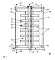
- Fig. 1 shows a section through a first Windungsfixier celebrating 10.
- a columnar member 14 in this case a support tube made of metal with a length of several meters, a lower 16 and an upper 18 holding member is arranged.
- a positioning region 22 for fixing a high-voltage winding pronounced which is indicated in this case by dashed lines with the reference numeral 12 as a hollow cylinder which extends rotationally symmetrical about the one extension axis 20.
- the retaining element 16 is designed as a plate-like sandwich construction made of metal and has a base area of about 2.8 m x 2.8 m, wherein on the left in the Fig.
- An unrolling device 52 is provided is about which the Wicklungsfixiervoretti 10 or fixed therein high-voltage winding 12 from a vertical mounting position in a horizontal transport position is tilted.
- a plurality of wooden bearing elements 48, 50 ring-like arranged around the extension axis 20. These have an approximately the same height, for example, 20 cm, and serve to protect a supported high-voltage winding 12 from any damage, for example, by a point too high pressure load. It is quite conceivable that recesses adapted to the shape of the bearing elements 48, 50 are provided in the plate-like holding element 16 in order to preclude their lateral slippage or mispositioning. But it is also conceivable to fix the bearing elements 48, 50 permanently on the holding element 16, for example by means of bonding.
- spacer elements 24, 28, which have a larger cross section adapted to the inner diameter of a winding to be fixed, are arranged in alternating sequence, and spacer elements 26, 30 are arranged with a significantly smaller cross section, the latter ultimately only the axial spacing of the other spacer elements 24, 28 serve with a larger cross-section.
- the spacer elements 24, 28 have in their middle a hole which is adapted to the diameter of the column-like element 14, so that a lateral displacement transverse to the extension axis 20 is excluded. Thus, a lateral displacement of a high-voltage winding 12 is excluded with a corresponding inner diameter.
- the spacers 24, 26, 28, 30 are loosely stacked and not interconnected.
- the upper retaining element 18 is - except for a non-existent tilting device - pronounced approximately analogous to the lower retaining element 16, wherein the compound slidably with the upper axial end of the columnar member 14, that is not screwed. Therefore, the upper support member 18 is completely detachable and removable, so that, if necessary, a free access from above to the positioning region 22 is ensured.
- bearing elements 44, 46 are provided between the upper holding element 18 and the positioning region.
- a tensile force 40 ⁇ 42 between the holding elements 16, 18 are provided, in this case tie rods 32, 34, 36, 38, which on both sides with are threaded.
- tie rods 32, 34, 36, 38 which on both sides with are threaded.
- corresponding threads are provided, so that an adjustable non-positive connection can be produced.
- a non-positive connection is possible, for example, a through hole in one of the holding elements and a pull rope with a corresponding thickening at one of its two ends. If the tether is guided with its non-thickened end through the through hole, a slipping of the thickened end is excluded by the through hole and thus also made a positive connection.
- a tensile force 40 ⁇ 42 of the tie rods 32, 34, 36, 38 causes a compression or a compressive force on a arranged between the holding elements high-voltage winding, so that this is stabilized and can be tilted without mechanical deformation together with the Windlungsfixiervorides in a horizontal position ,
- a screw connection 54 is provided at the upper axial end of the column-like element 20.
- Fig. 2 shows a plan view 60 on an exemplary holding member 62 with a square outline.
- threaded holes 80, 82 are provided in pairs in different distance radii to the center, which serve to receive tie rods with corresponding threads.
- the threaded holes 80, 82 selected with the matching distance radii.
- the radially outer threaded holes protrude beyond the outer radius of a high-voltage winding arranged on the holding element 62, so that they also constitute a mechanical protection for the high-voltage winding.
- a dashed line Indicated by a dashed line are the trapezium-like base surfaces of four bearing elements 64, 66, 68, 70, which are arranged annularly around the center of the square retaining element 62.
- a column-like element 72 Perpendicular to the holding element 62, a column-like element 72 is arranged in the center thereof.
- a total of eight internal threaded holes are provided, in which tie rods can be screwed, which then extend in the inner region of a arranged on the holding member 62 hollow cylindrical high voltage winding.
- tie rods can be screwed, which then extend in the inner region of a arranged on the holding member 62 hollow cylindrical high voltage winding.
- a high-voltage winding is then preferably by means of a total of sixteen tie rods or tension cables braced.
- the base area of the positioning area for an arrangement of high-voltage windings is indicated by a circle with the reference number 78, wherein the circle with the reference number
- Fig. 3 shows a section 90 through a second Windungsfixier adopted with a high-voltage winding 98.
- the Windlungsfixier In the corner regions of the Windlungsfixier acquired two tie rods are shown in cross section, which also provide a mechanical protection for the high-voltage winding 98, in the inner region of a cross-section adapted to the spacer element 92 shown is.
- This has a total of four Einschlitzonne 94 through which also indicated with its cross section inner tie rods are guided.
- a column-like element 96 is arranged, which is guided through a corresponding bore through the spacer element 92.
- a membrane Congruent with the outer edges of the square base of the Wicklungsfixier worn indicated by the reference numeral 100 is a membrane which surrounds the corresponding positioning region. Such a membrane prevents, for example, in the case of a sea transport moisture penetration into the high-voltage winding to be transported, by adjusting the volume creates a pressure equalization between internal and external pressure and thus prevents an exchange between the dry indoor air by humid outside air.
- Fig. 4 shows a section 110 through a lying Windungsfixier adopted with high voltage winding fixed therein, which in some of the Fig. 1 corresponds to Windungsfixier worn shown.
- the orientation indicated by the reference numeral 112 is thus horizontal.
- the device is arranged in a standard transport container 114, so that it can be easily transported by train, truck or container ships.
- the tilting of the device in the horizontal transport position has been previously on the direction indicated by the reference numeral 124 tilting device, in this case, a rolling edge occurs.
- a radial support of the high-voltage winding is effected by adapted to the inner diameter of the high-voltage winding spacers 118, 122, which are tilted in this case with wedges 116 in order to exclude any movement play.
Landscapes
- Engineering & Computer Science (AREA)
- Power Engineering (AREA)
- Mechanical Engineering (AREA)
- Storage Of Web-Like Or Filamentary Materials (AREA)
- Coils Of Transformers For General Uses (AREA)
- Electromagnets (AREA)
- Clamps And Clips (AREA)
- Warehouses Or Storage Devices (AREA)
Priority Applications (7)
| Application Number | Priority Date | Filing Date | Title |
|---|---|---|---|
| ES11003901.3T ES2451390T3 (es) | 2011-05-12 | 2011-05-12 | Dispositivo de fijación de arrollamiento |
| EP11003901.3A EP2523196B1 (fr) | 2011-05-12 | 2011-05-12 | Dispositif de fixation d'enroulement |
| BR112013028713-6A BR112013028713B1 (pt) | 2011-05-12 | 2012-03-10 | Dispositivo de fixação de bobina |
| CA2835374A CA2835374C (fr) | 2011-05-12 | 2012-03-10 | Dispositif de fixation d'un enroulement |
| CN201280022881.6A CN103503090B (zh) | 2011-05-12 | 2012-03-10 | 线圈固定装置 |
| PCT/EP2012/001086 WO2012152351A1 (fr) | 2011-05-12 | 2012-03-10 | Dispositif de fixation d'un enroulement |
| US14/077,872 US9580270B2 (en) | 2011-05-12 | 2013-11-12 | Winding fixing device |
Applications Claiming Priority (1)
| Application Number | Priority Date | Filing Date | Title |
|---|---|---|---|
| EP11003901.3A EP2523196B1 (fr) | 2011-05-12 | 2011-05-12 | Dispositif de fixation d'enroulement |
Publications (2)
| Publication Number | Publication Date |
|---|---|
| EP2523196A1 true EP2523196A1 (fr) | 2012-11-14 |
| EP2523196B1 EP2523196B1 (fr) | 2014-01-15 |
Family
ID=45815492
Family Applications (1)
| Application Number | Title | Priority Date | Filing Date |
|---|---|---|---|
| EP11003901.3A Active EP2523196B1 (fr) | 2011-05-12 | 2011-05-12 | Dispositif de fixation d'enroulement |
Country Status (7)
| Country | Link |
|---|---|
| US (1) | US9580270B2 (fr) |
| EP (1) | EP2523196B1 (fr) |
| CN (1) | CN103503090B (fr) |
| BR (1) | BR112013028713B1 (fr) |
| CA (1) | CA2835374C (fr) |
| ES (1) | ES2451390T3 (fr) |
| WO (1) | WO2012152351A1 (fr) |
Cited By (2)
| Publication number | Priority date | Publication date | Assignee | Title |
|---|---|---|---|---|
| CN107654842A (zh) * | 2017-09-22 | 2018-02-02 | 江苏江海船舶设备制造有限公司 | 一种船舶用空气瓶支架 |
| CN108674793A (zh) * | 2018-05-29 | 2018-10-19 | 保定天威保变电气股份有限公司 | 一种局部解体式变压器铁芯固定方法及装置 |
Families Citing this family (6)
| Publication number | Priority date | Publication date | Assignee | Title |
|---|---|---|---|---|
| ES2798303T3 (es) * | 2014-10-07 | 2020-12-10 | Abb Power Grids Switzerland Ag | Transformador para vehículo |
| CN108031575B (zh) * | 2017-12-10 | 2020-11-24 | 天长市金陵电子有限责任公司 | 一种用于静电喷涂设备中的管道盘卷装置 |
| CN109367984A (zh) * | 2018-09-27 | 2019-02-22 | 中国电力科学研究院有限公司 | 解体式特高压变压器整套线圈运输装置 |
| EP3955270A1 (fr) * | 2020-08-11 | 2022-02-16 | Hitachi Energy Switzerland AG | Agencement d'enroulement, transformateur et procédé de production d'un agencement d'enroulement |
| CN112614650B (zh) * | 2020-12-30 | 2025-01-28 | 江西鑫聚盛电气设备有限公司 | 一种双电压防盗变压器 |
| CN116487164A (zh) * | 2023-03-23 | 2023-07-25 | 陕西四方华能电气设备有限公司 | 一种变压器线圈及具有该线圈的变压器 |
Citations (5)
| Publication number | Priority date | Publication date | Assignee | Title |
|---|---|---|---|---|
| DE3027883A1 (de) * | 1979-08-09 | 1981-02-26 | Asea Ab | Verfahren zum einspannen der wicklung in einen transformator |
| JPS5914623A (ja) * | 1982-07-15 | 1984-01-25 | Fuji Electric Co Ltd | パツクコイルの輸送方法 |
| DE10250957B3 (de) * | 2002-10-29 | 2004-08-19 | Siemens Ag | Wicklungsanordnung |
| JP2009049276A (ja) * | 2007-08-22 | 2009-03-05 | Toshiba Corp | 巻線輸送タンクおよび巻線輸送方法 |
| EP2355115A1 (fr) * | 2010-02-08 | 2011-08-10 | ABB Technology AG | Boîtier de transport pour une bobine ou un bloc de bobinage |
Family Cites Families (8)
| Publication number | Priority date | Publication date | Assignee | Title |
|---|---|---|---|---|
| US2466448A (en) * | 1946-06-25 | 1949-04-05 | Gen Electric | Combined core and coil clamp |
| CH417760A (de) * | 1964-12-10 | 1966-07-31 | Oerlikon Maschf | Wicklung, insbesondere für Grosstransformatoren |
| US3796333A (en) * | 1971-08-13 | 1974-03-12 | K Goldstein | Detachable carrier for vehicles |
| JPH10250957A (ja) | 1997-03-07 | 1998-09-22 | Riko Kogyo Kk | エレベーター |
| DE10008220A1 (de) * | 2000-02-23 | 2001-08-30 | Roland Man Druckmasch | Gestell eines Druckwerkes |
| DE102005058119B4 (de) * | 2005-11-29 | 2008-01-10 | Siemens Ag | Fixiervorrichtung für eine elektrische Wicklung |
| JP4891871B2 (ja) * | 2007-09-06 | 2012-03-07 | 株式会社東芝 | 変圧器輸送組立方法およびu字形鉄心組立装置 |
| US8393659B2 (en) * | 2011-03-23 | 2013-03-12 | Brad Stroh | Material handling system |
-
2011
- 2011-05-12 ES ES11003901.3T patent/ES2451390T3/es active Active
- 2011-05-12 EP EP11003901.3A patent/EP2523196B1/fr active Active
-
2012
- 2012-03-10 CN CN201280022881.6A patent/CN103503090B/zh active Active
- 2012-03-10 CA CA2835374A patent/CA2835374C/fr active Active
- 2012-03-10 BR BR112013028713-6A patent/BR112013028713B1/pt active IP Right Grant
- 2012-03-10 WO PCT/EP2012/001086 patent/WO2012152351A1/fr not_active Ceased
-
2013
- 2013-11-12 US US14/077,872 patent/US9580270B2/en active Active
Patent Citations (5)
| Publication number | Priority date | Publication date | Assignee | Title |
|---|---|---|---|---|
| DE3027883A1 (de) * | 1979-08-09 | 1981-02-26 | Asea Ab | Verfahren zum einspannen der wicklung in einen transformator |
| JPS5914623A (ja) * | 1982-07-15 | 1984-01-25 | Fuji Electric Co Ltd | パツクコイルの輸送方法 |
| DE10250957B3 (de) * | 2002-10-29 | 2004-08-19 | Siemens Ag | Wicklungsanordnung |
| JP2009049276A (ja) * | 2007-08-22 | 2009-03-05 | Toshiba Corp | 巻線輸送タンクおよび巻線輸送方法 |
| EP2355115A1 (fr) * | 2010-02-08 | 2011-08-10 | ABB Technology AG | Boîtier de transport pour une bobine ou un bloc de bobinage |
Cited By (2)
| Publication number | Priority date | Publication date | Assignee | Title |
|---|---|---|---|---|
| CN107654842A (zh) * | 2017-09-22 | 2018-02-02 | 江苏江海船舶设备制造有限公司 | 一种船舶用空气瓶支架 |
| CN108674793A (zh) * | 2018-05-29 | 2018-10-19 | 保定天威保变电气股份有限公司 | 一种局部解体式变压器铁芯固定方法及装置 |
Also Published As
| Publication number | Publication date |
|---|---|
| EP2523196B1 (fr) | 2014-01-15 |
| US20140151492A1 (en) | 2014-06-05 |
| CN103503090B (zh) | 2016-12-07 |
| CA2835374C (fr) | 2017-12-12 |
| WO2012152351A1 (fr) | 2012-11-15 |
| US9580270B2 (en) | 2017-02-28 |
| BR112013028713B1 (pt) | 2020-03-31 |
| ES2451390T3 (es) | 2014-03-26 |
| CN103503090A (zh) | 2014-01-08 |
| CA2835374A1 (fr) | 2012-11-15 |
| BR112013028713A2 (pt) | 2017-01-24 |
Similar Documents
| Publication | Publication Date | Title |
|---|---|---|
| EP2523196B1 (fr) | Dispositif de fixation d'enroulement | |
| EP2549495B1 (fr) | Transformateur à sec | |
| EP2355115B1 (fr) | Boîtier de transport pour une bobine ou un bloc de bobinage | |
| EP3493229A1 (fr) | Dispositif de presse pour bobines de transformateurs | |
| WO2007121881A1 (fr) | Système de LIAISON de support | |
| EP2590185B1 (fr) | Module de transformateur haute tension | |
| DE3027883C2 (de) | Verfahren zum Einspannen der Wicklung in einen Transformator | |
| EP3577664B1 (fr) | Dispositif électrique avec une réservoir d'une forme complémentaire à la partie active | |
| EP1959460B1 (fr) | Procédé de fabrication d'un transformateur | |
| EP3711127B1 (fr) | Enrouleur de câble pour un câble à haute tension | |
| DE202017100456U1 (de) | Stützenteil für eine mobile Hochwasserschutzwand aus Dammbalkensystemen | |
| EP3580402B1 (fr) | Support à structure segmentée | |
| EP2239745B1 (fr) | Transformateur de performance doté d'un noyau amorphe | |
| EP0477423B1 (fr) | Système de liaison pour cadres | |
| AT521505B1 (de) | Verfahren zum Bereitstellen, Transportieren und Aufstellen von Spulen einer Spulenbaugruppe | |
| WO2018184774A1 (fr) | Appareil électrique comprenant un composant actif fixé à la cuve par l'intermédiaire de boulons de culasse | |
| DE102017005120B4 (de) | Transformator | |
| DE102016215646A1 (de) | Mehrstocktransformator für ein Verteilnetz oder den Betrieb mit einem Umrichter | |
| EP3133615A1 (fr) | Systeme de bobine electrique | |
| DE2832293C2 (de) | Anordnung zur Abstützung von Transformatorenwicklungen mit rechteckigem Querschnitt | |
| EP3577665A1 (fr) | Composant actif pour appareil électrique haute tension | |
| DE4430760C2 (de) | Verfahren und Vorrichtung zum Auswechseln eines Mastkopfes eines Abspannmastes einer Hochspannungsfreileitung | |
| DE2444797C3 (de) | Gestell zum Halten und Pressen von Wicklungen in Transformatoren | |
| DE1413534C (de) | Vorrichtung zur gemeinsamen Pressung der Kerne und Wicklungen von großen Transformatoren | |
| DE102021120692A1 (de) | Kabinenmodul für einen behandlungstunnel einer behandlungsanlage, behandlungstunnel und behandlungsanlage |
Legal Events
| Date | Code | Title | Description |
|---|---|---|---|
| PUAI | Public reference made under article 153(3) epc to a published international application that has entered the european phase |
Free format text: ORIGINAL CODE: 0009012 |
|
| AK | Designated contracting states |
Kind code of ref document: A1 Designated state(s): AL AT BE BG CH CY CZ DE DK EE ES FI FR GB GR HR HU IE IS IT LI LT LU LV MC MK MT NL NO PL PT RO RS SE SI SK SM TR |
|
| AX | Request for extension of the european patent |
Extension state: BA ME |
|
| 17P | Request for examination filed |
Effective date: 20121206 |
|
| GRAP | Despatch of communication of intention to grant a patent |
Free format text: ORIGINAL CODE: EPIDOSNIGR1 |
|
| INTG | Intention to grant announced |
Effective date: 20131018 |
|
| GRAS | Grant fee paid |
Free format text: ORIGINAL CODE: EPIDOSNIGR3 |
|
| GRAA | (expected) grant |
Free format text: ORIGINAL CODE: 0009210 |
|
| AK | Designated contracting states |
Kind code of ref document: B1 Designated state(s): AL AT BE BG CH CY CZ DE DK EE ES FI FR GB GR HR HU IE IS IT LI LT LU LV MC MK MT NL NO PL PT RO RS SE SI SK SM TR |
|
| REG | Reference to a national code |
Ref country code: CH Ref legal event code: EP Ref country code: GB Ref legal event code: FG4D Free format text: NOT ENGLISH |
|
| REG | Reference to a national code |
Ref country code: AT Ref legal event code: REF Ref document number: 650141 Country of ref document: AT Kind code of ref document: T Effective date: 20140215 |
|
| REG | Reference to a national code |
Ref country code: IE Ref legal event code: FG4D Free format text: LANGUAGE OF EP DOCUMENT: GERMAN |
|
| REG | Reference to a national code |
Ref country code: DE Ref legal event code: R096 Ref document number: 502011002022 Country of ref document: DE Effective date: 20140306 |
|
| REG | Reference to a national code |
Ref country code: ES Ref legal event code: FG2A Ref document number: 2451390 Country of ref document: ES Kind code of ref document: T3 Effective date: 20140326 |
|
| REG | Reference to a national code |
Ref country code: SE Ref legal event code: TRGR |
|
| REG | Reference to a national code |
Ref country code: NL Ref legal event code: VDEP Effective date: 20140115 |
|
| REG | Reference to a national code |
Ref country code: LT Ref legal event code: MG4D |
|
| PG25 | Lapsed in a contracting state [announced via postgrant information from national office to epo] |
Ref country code: NO Free format text: LAPSE BECAUSE OF FAILURE TO SUBMIT A TRANSLATION OF THE DESCRIPTION OR TO PAY THE FEE WITHIN THE PRESCRIBED TIME-LIMIT Effective date: 20140415 Ref country code: IS Free format text: LAPSE BECAUSE OF FAILURE TO SUBMIT A TRANSLATION OF THE DESCRIPTION OR TO PAY THE FEE WITHIN THE PRESCRIBED TIME-LIMIT Effective date: 20140515 Ref country code: LT Free format text: LAPSE BECAUSE OF FAILURE TO SUBMIT A TRANSLATION OF THE DESCRIPTION OR TO PAY THE FEE WITHIN THE PRESCRIBED TIME-LIMIT Effective date: 20140115 |
|
| PG25 | Lapsed in a contracting state [announced via postgrant information from national office to epo] |
Ref country code: PT Free format text: LAPSE BECAUSE OF FAILURE TO SUBMIT A TRANSLATION OF THE DESCRIPTION OR TO PAY THE FEE WITHIN THE PRESCRIBED TIME-LIMIT Effective date: 20140515 Ref country code: NL Free format text: LAPSE BECAUSE OF FAILURE TO SUBMIT A TRANSLATION OF THE DESCRIPTION OR TO PAY THE FEE WITHIN THE PRESCRIBED TIME-LIMIT Effective date: 20140115 Ref country code: CY Free format text: LAPSE BECAUSE OF FAILURE TO SUBMIT A TRANSLATION OF THE DESCRIPTION OR TO PAY THE FEE WITHIN THE PRESCRIBED TIME-LIMIT Effective date: 20140115 |
|
| PG25 | Lapsed in a contracting state [announced via postgrant information from national office to epo] |
Ref country code: HR Free format text: LAPSE BECAUSE OF FAILURE TO SUBMIT A TRANSLATION OF THE DESCRIPTION OR TO PAY THE FEE WITHIN THE PRESCRIBED TIME-LIMIT Effective date: 20140115 Ref country code: RS Free format text: LAPSE BECAUSE OF FAILURE TO SUBMIT A TRANSLATION OF THE DESCRIPTION OR TO PAY THE FEE WITHIN THE PRESCRIBED TIME-LIMIT Effective date: 20140115 Ref country code: LV Free format text: LAPSE BECAUSE OF FAILURE TO SUBMIT A TRANSLATION OF THE DESCRIPTION OR TO PAY THE FEE WITHIN THE PRESCRIBED TIME-LIMIT Effective date: 20140115 |
|
| REG | Reference to a national code |
Ref country code: DE Ref legal event code: R097 Ref document number: 502011002022 Country of ref document: DE |
|
| PG25 | Lapsed in a contracting state [announced via postgrant information from national office to epo] |
Ref country code: EE Free format text: LAPSE BECAUSE OF FAILURE TO SUBMIT A TRANSLATION OF THE DESCRIPTION OR TO PAY THE FEE WITHIN THE PRESCRIBED TIME-LIMIT Effective date: 20140115 Ref country code: RO Free format text: LAPSE BECAUSE OF FAILURE TO SUBMIT A TRANSLATION OF THE DESCRIPTION OR TO PAY THE FEE WITHIN THE PRESCRIBED TIME-LIMIT Effective date: 20140115 Ref country code: CZ Free format text: LAPSE BECAUSE OF FAILURE TO SUBMIT A TRANSLATION OF THE DESCRIPTION OR TO PAY THE FEE WITHIN THE PRESCRIBED TIME-LIMIT Effective date: 20140115 Ref country code: DK Free format text: LAPSE BECAUSE OF FAILURE TO SUBMIT A TRANSLATION OF THE DESCRIPTION OR TO PAY THE FEE WITHIN THE PRESCRIBED TIME-LIMIT Effective date: 20140115 |
|
| PLBE | No opposition filed within time limit |
Free format text: ORIGINAL CODE: 0009261 |
|
| STAA | Information on the status of an ep patent application or granted ep patent |
Free format text: STATUS: NO OPPOSITION FILED WITHIN TIME LIMIT |
|
| PG25 | Lapsed in a contracting state [announced via postgrant information from national office to epo] |
Ref country code: PL Free format text: LAPSE BECAUSE OF FAILURE TO SUBMIT A TRANSLATION OF THE DESCRIPTION OR TO PAY THE FEE WITHIN THE PRESCRIBED TIME-LIMIT Effective date: 20140115 Ref country code: SK Free format text: LAPSE BECAUSE OF FAILURE TO SUBMIT A TRANSLATION OF THE DESCRIPTION OR TO PAY THE FEE WITHIN THE PRESCRIBED TIME-LIMIT Effective date: 20140115 |
|
| 26N | No opposition filed |
Effective date: 20141016 |
|
| PG25 | Lapsed in a contracting state [announced via postgrant information from national office to epo] |
Ref country code: LU Free format text: LAPSE BECAUSE OF FAILURE TO SUBMIT A TRANSLATION OF THE DESCRIPTION OR TO PAY THE FEE WITHIN THE PRESCRIBED TIME-LIMIT Effective date: 20140512 |
|
| REG | Reference to a national code |
Ref country code: CH Ref legal event code: PL |
|
| PG25 | Lapsed in a contracting state [announced via postgrant information from national office to epo] |
Ref country code: LI Free format text: LAPSE BECAUSE OF NON-PAYMENT OF DUE FEES Effective date: 20140531 Ref country code: CH Free format text: LAPSE BECAUSE OF NON-PAYMENT OF DUE FEES Effective date: 20140531 Ref country code: MC Free format text: LAPSE BECAUSE OF FAILURE TO SUBMIT A TRANSLATION OF THE DESCRIPTION OR TO PAY THE FEE WITHIN THE PRESCRIBED TIME-LIMIT Effective date: 20140115 |
|
| REG | Reference to a national code |
Ref country code: DE Ref legal event code: R097 Ref document number: 502011002022 Country of ref document: DE Effective date: 20141016 |
|
| REG | Reference to a national code |
Ref country code: IE Ref legal event code: MM4A |
|
| PG25 | Lapsed in a contracting state [announced via postgrant information from national office to epo] |
Ref country code: IE Free format text: LAPSE BECAUSE OF NON-PAYMENT OF DUE FEES Effective date: 20140512 |
|
| PG25 | Lapsed in a contracting state [announced via postgrant information from national office to epo] |
Ref country code: SI Free format text: LAPSE BECAUSE OF FAILURE TO SUBMIT A TRANSLATION OF THE DESCRIPTION OR TO PAY THE FEE WITHIN THE PRESCRIBED TIME-LIMIT Effective date: 20140115 |
|
| PG25 | Lapsed in a contracting state [announced via postgrant information from national office to epo] |
Ref country code: MT Free format text: LAPSE BECAUSE OF FAILURE TO SUBMIT A TRANSLATION OF THE DESCRIPTION OR TO PAY THE FEE WITHIN THE PRESCRIBED TIME-LIMIT Effective date: 20140115 |
|
| PG25 | Lapsed in a contracting state [announced via postgrant information from national office to epo] |
Ref country code: SM Free format text: LAPSE BECAUSE OF FAILURE TO SUBMIT A TRANSLATION OF THE DESCRIPTION OR TO PAY THE FEE WITHIN THE PRESCRIBED TIME-LIMIT Effective date: 20140115 |
|
| REG | Reference to a national code |
Ref country code: FR Ref legal event code: PLFP Year of fee payment: 6 |
|
| PG25 | Lapsed in a contracting state [announced via postgrant information from national office to epo] |
Ref country code: GR Free format text: LAPSE BECAUSE OF FAILURE TO SUBMIT A TRANSLATION OF THE DESCRIPTION OR TO PAY THE FEE WITHIN THE PRESCRIBED TIME-LIMIT Effective date: 20140416 Ref country code: BG Free format text: LAPSE BECAUSE OF FAILURE TO SUBMIT A TRANSLATION OF THE DESCRIPTION OR TO PAY THE FEE WITHIN THE PRESCRIBED TIME-LIMIT Effective date: 20140115 |
|
| PG25 | Lapsed in a contracting state [announced via postgrant information from national office to epo] |
Ref country code: BE Free format text: LAPSE BECAUSE OF FAILURE TO SUBMIT A TRANSLATION OF THE DESCRIPTION OR TO PAY THE FEE WITHIN THE PRESCRIBED TIME-LIMIT Effective date: 20140531 Ref country code: HU Free format text: LAPSE BECAUSE OF FAILURE TO SUBMIT A TRANSLATION OF THE DESCRIPTION OR TO PAY THE FEE WITHIN THE PRESCRIBED TIME-LIMIT; INVALID AB INITIO Effective date: 20110512 Ref country code: TR Free format text: LAPSE BECAUSE OF FAILURE TO SUBMIT A TRANSLATION OF THE DESCRIPTION OR TO PAY THE FEE WITHIN THE PRESCRIBED TIME-LIMIT Effective date: 20140115 |
|
| REG | Reference to a national code |
Ref country code: DE Ref legal event code: R081 Ref document number: 502011002022 Country of ref document: DE Owner name: HITACHI ENERGY SWITZERLAND AG, CH Free format text: FORMER OWNER: ABB TECHNOLOGY AG, ZUERICH, CH Ref country code: DE Ref legal event code: R081 Ref document number: 502011002022 Country of ref document: DE Owner name: ABB POWER GRIDS SWITZERLAND AG, CH Free format text: FORMER OWNER: ABB TECHNOLOGY AG, ZUERICH, CH Ref country code: DE Ref legal event code: R081 Ref document number: 502011002022 Country of ref document: DE Owner name: ABB SCHWEIZ AG, CH Free format text: FORMER OWNER: ABB TECHNOLOGY AG, ZUERICH, CH |
|
| REG | Reference to a national code |
Ref country code: FR Ref legal event code: PLFP Year of fee payment: 7 |
|
| REG | Reference to a national code |
Ref country code: AT Ref legal event code: MM01 Ref document number: 650141 Country of ref document: AT Kind code of ref document: T Effective date: 20160512 |
|
| PG25 | Lapsed in a contracting state [announced via postgrant information from national office to epo] |
Ref country code: AT Free format text: LAPSE BECAUSE OF NON-PAYMENT OF DUE FEES Effective date: 20160512 |
|
| PGFP | Annual fee paid to national office [announced via postgrant information from national office to epo] |
Ref country code: FI Payment date: 20170511 Year of fee payment: 7 Ref country code: SE Payment date: 20170519 Year of fee payment: 7 |
|
| REG | Reference to a national code |
Ref country code: ES Ref legal event code: PC2A Owner name: ABB SCHWEIZ AG Effective date: 20171218 |
|
| REG | Reference to a national code |
Ref country code: FR Ref legal event code: PLFP Year of fee payment: 8 |
|
| REG | Reference to a national code |
Ref country code: GB Ref legal event code: 732E Free format text: REGISTERED BETWEEN 20180426 AND 20180502 |
|
| PG25 | Lapsed in a contracting state [announced via postgrant information from national office to epo] |
Ref country code: MK Free format text: LAPSE BECAUSE OF FAILURE TO SUBMIT A TRANSLATION OF THE DESCRIPTION OR TO PAY THE FEE WITHIN THE PRESCRIBED TIME-LIMIT Effective date: 20140115 |
|
| REG | Reference to a national code |
Ref country code: FR Ref legal event code: TP Owner name: ABB SCHWEIZ AG, CH Effective date: 20180912 |
|
| PG25 | Lapsed in a contracting state [announced via postgrant information from national office to epo] |
Ref country code: AL Free format text: LAPSE BECAUSE OF FAILURE TO SUBMIT A TRANSLATION OF THE DESCRIPTION OR TO PAY THE FEE WITHIN THE PRESCRIBED TIME-LIMIT Effective date: 20140115 |
|
| REG | Reference to a national code |
Ref country code: SE Ref legal event code: EUG |
|
| PG25 | Lapsed in a contracting state [announced via postgrant information from national office to epo] |
Ref country code: SE Free format text: LAPSE BECAUSE OF NON-PAYMENT OF DUE FEES Effective date: 20180513 Ref country code: FI Free format text: LAPSE BECAUSE OF NON-PAYMENT OF DUE FEES Effective date: 20180512 |
|
| REG | Reference to a national code |
Ref country code: DE Ref legal event code: R081 Ref document number: 502011002022 Country of ref document: DE Owner name: HITACHI ENERGY SWITZERLAND AG, CH Free format text: FORMER OWNER: ABB SCHWEIZ AG, BADEN, CH Ref country code: DE Ref legal event code: R081 Ref document number: 502011002022 Country of ref document: DE Owner name: HITACHI ENERGY LTD, CH Free format text: FORMER OWNER: ABB SCHWEIZ AG, BADEN, CH Ref country code: DE Ref legal event code: R081 Ref document number: 502011002022 Country of ref document: DE Owner name: ABB POWER GRIDS SWITZERLAND AG, CH Free format text: FORMER OWNER: ABB SCHWEIZ AG, BADEN, CH |
|
| REG | Reference to a national code |
Ref country code: ES Ref legal event code: PC2A Owner name: ABB POWER GRIDS SWITZERLAND AG Effective date: 20210520 |
|
| REG | Reference to a national code |
Ref country code: GB Ref legal event code: 732E Free format text: REGISTERED BETWEEN 20211104 AND 20211110 |
|
| REG | Reference to a national code |
Ref country code: ES Ref legal event code: PC2A Owner name: HITACHI ENERGY SWITZERLAND AG Effective date: 20220526 |
|
| REG | Reference to a national code |
Ref country code: DE Ref legal event code: R081 Ref document number: 502011002022 Country of ref document: DE Owner name: HITACHI ENERGY SWITZERLAND AG, CH Free format text: FORMER OWNER: ABB POWER GRIDS SWITZERLAND AG, BADEN, CH Ref country code: DE Ref legal event code: R081 Ref document number: 502011002022 Country of ref document: DE Owner name: HITACHI ENERGY LTD, CH Free format text: FORMER OWNER: ABB POWER GRIDS SWITZERLAND AG, BADEN, CH |
|
| P01 | Opt-out of the competence of the unified patent court (upc) registered |
Effective date: 20230527 |
|
| REG | Reference to a national code |
Ref country code: DE Ref legal event code: R082 Ref document number: 502011002022 Country of ref document: DE Representative=s name: DENNEMEYER & ASSOCIATES RECHTSANWALTSGESELLSCH, DE Ref country code: DE Ref legal event code: R082 Ref document number: 502011002022 Country of ref document: DE Representative=s name: DENNEMEYER & ASSOCIATES S.A., DE Ref country code: DE Ref legal event code: R081 Ref document number: 502011002022 Country of ref document: DE Owner name: HITACHI ENERGY LTD, CH Free format text: FORMER OWNER: HITACHI ENERGY SWITZERLAND AG, BADEN, CH |
|
| REG | Reference to a national code |
Ref country code: GB Ref legal event code: 732E Free format text: REGISTERED BETWEEN 20240718 AND 20240724 |
|
| REG | Reference to a national code |
Ref country code: ES Ref legal event code: PC2A Owner name: HITACHI ENERGY LTD Effective date: 20240925 |
|
| REG | Reference to a national code |
Ref country code: DE Ref legal event code: R082 Ref document number: 502011002022 Country of ref document: DE Representative=s name: DENNEMEYER & ASSOCIATES RECHTSANWALTSGESELLSCH, DE |
|
| PGFP | Annual fee paid to national office [announced via postgrant information from national office to epo] |
Ref country code: DE Payment date: 20250521 Year of fee payment: 15 |
|
| PGFP | Annual fee paid to national office [announced via postgrant information from national office to epo] |
Ref country code: GB Payment date: 20250526 Year of fee payment: 15 Ref country code: ES Payment date: 20250627 Year of fee payment: 15 |
|
| PGFP | Annual fee paid to national office [announced via postgrant information from national office to epo] |
Ref country code: IT Payment date: 20250527 Year of fee payment: 15 |
|
| PGFP | Annual fee paid to national office [announced via postgrant information from national office to epo] |
Ref country code: FR Payment date: 20250528 Year of fee payment: 15 |