EP2523285A1 - Kabelrahmen-verkabelungsstruktur - Google Patents
Kabelrahmen-verkabelungsstruktur Download PDFInfo
- Publication number
- EP2523285A1 EP2523285A1 EP11731805A EP11731805A EP2523285A1 EP 2523285 A1 EP2523285 A1 EP 2523285A1 EP 11731805 A EP11731805 A EP 11731805A EP 11731805 A EP11731805 A EP 11731805A EP 2523285 A1 EP2523285 A1 EP 2523285A1
- Authority
- EP
- European Patent Office
- Prior art keywords
- wire harness
- movable
- installing
- seat
- movable part
- Prior art date
- Legal status (The legal status is an assumption and is not a legal conclusion. Google has not performed a legal analysis and makes no representation as to the accuracy of the status listed.)
- Granted
Links
Images





Classifications
-
- B—PERFORMING OPERATIONS; TRANSPORTING
- B60—VEHICLES IN GENERAL
- B60R—VEHICLES, VEHICLE FITTINGS, OR VEHICLE PARTS, NOT OTHERWISE PROVIDED FOR
- B60R16/00—Electric or fluid circuits specially adapted for vehicles and not otherwise provided for; Arrangement of elements of electric or fluid circuits specially adapted for vehicles and not otherwise provided for
- B60R16/02—Electric or fluid circuits specially adapted for vehicles and not otherwise provided for; Arrangement of elements of electric or fluid circuits specially adapted for vehicles and not otherwise provided for electric constitutive elements
- B60R16/0207—Wire harnesses
- B60R16/0215—Protecting, fastening and routing means therefor
-
- B—PERFORMING OPERATIONS; TRANSPORTING
- B60—VEHICLES IN GENERAL
- B60N—SEATS SPECIALLY ADAPTED FOR VEHICLES; VEHICLE PASSENGER ACCOMMODATION NOT OTHERWISE PROVIDED FOR
- B60N2/00—Seats specially adapted for vehicles; Arrangement or mounting of seats in vehicles
- B60N2/02—Seats specially adapted for vehicles; Arrangement or mounting of seats in vehicles the seat or part thereof being movable, e.g. adjustable
- B60N2/0224—Non-manual adjustments, e.g. with electrical operation
- B60N2/0244—Non-manual adjustments, e.g. with electrical operation with logic circuits
- B60N2/0264—Non-manual adjustments, e.g. with electrical operation with logic circuits characterised by the type of electrical connection, e.g. wiring, plugs or USB
-
- H—ELECTRICITY
- H02—GENERATION; CONVERSION OR DISTRIBUTION OF ELECTRIC POWER
- H02G—INSTALLATION OF ELECTRIC CABLES OR LINES, OR OF COMBINED OPTICAL AND ELECTRIC CABLES OR LINES
- H02G11/00—Arrangements of electric cables or lines between relatively-movable parts
Definitions
- the present invention relates to a wire harness installing structure, and more particularly to an improvement for saving a space of an installation area while improving an installing workability.
- a vehicle seat includes a power seat device that adjusts the position of a seat cushion in a forward-backward direction and in a vertical direction in conformity to the posture of a passenger or reclines a seat back, and an air back unit device that is developed between the passenger and a side door.
- a wire harness is installed in the vehicle seat on which the above device is mounted for feeding power to electric parts.
- FIGS. 10 and 11 illustrate a conventional example of the wire harness installing structure in the vehicle seat.
- a wire harness 108 is installed to a seat back 104 from a lower side of a seat cushion within a vehicle seat 106 which has the seat back 104 is provided on a side frame 102 so as to be reclined with a horizontal rotating shaft 105.
- the seat cushion (not shown) is provided on the side frame 102.
- a wire harness 108 is covered and protected with a corrugated tube 109 on an installing path.
- an intermediate part 109a of the wire harness 108 is installed along the rotating shaft 105 in parallel, the intermediate part 109a is fixed to the rotating shaft 105 by a clamp 110, portions continuous to both sides of the intermediate part 109a are fixed to the seat cushion and the seat back 104 by other clamps 112 and 114, respectively.
- Patent Document 1 JP-A-2006-304538
- an object of the present invention is to provide a wire harness installing structure that can improve an installing workability of the wire harness, and save a space of a installation area.
- a wire harness installing structure in which a wire harness that bundles a plurality of electric wires into a bundle state is installed between two structures across a movable linking part that movably couples first and second structures, wherein a movable part installing section of the wire harness arranged in a predetermined length interval across the movable linking part includes: an non bundled part in which the electric wires are movable respectively without being bundled; and a stretchable protective member which covers an outer periphery of the non bundled part so as not to restrict a movable state of the electric wires.
- the wire harness installing structure according to the above (1) further comprising: a first fixing part that fixes one end of the movable part installing section to the first structure; and a second fixing part that fixes the other end of the movable part installing section to the second structure.
- the first fixing part and the second fixing part are arranged so as to set to be displaced in a direction orthogonal to a relative movement direction of the first fixing part and the second fixing part due to a mutual movement of the structures.
- the movable part installing section extending across the movable linking part has a high flexibility because the electric wires are not mutually bundled by a protective sheath or a tape, and the respective electric wires are freely movable in the radial direction. Accordingly, even if the bundle of electric wires of the wire harness becomes thicker, the wire harness can be easily bent at the movable part installing section. Therefore, the installing workability can be improved.
- the wire harness can be easily bent at the movable part installing section, the bend radius does not become larger, and the installation area can be saved in space.
- the wire harness is moved and widened in one direction of the radial directions so as to be flattened, and the wire harness can be bent at the movable part installing section. Therefore, no wide space is required for changing the installing direction, and the installation area can be saved in space.
- the stretchable protective member provided on the movable part installing section appropriately suppresses the movement of the respective electric wires to prevent the outer diameter of the movable part installing section from being casually enlarged during the bending operation. Therefore, the stretchable protective member contributes to the space saving of the installation area.
- the bend state of the movable part installing section 25 is changed with the mutually moving operation of the two structures.
- the mutually moving operation of the two structures can be flexibly permitted.
- the electric wires moving in a direction orthogonal to an extending direction of the electric wires when the movable part installing section is bent does not directly contact the peripheral structure so that the wire harness can be prevented from being damaged.
- the movable part installing section deals with the relative movement by both of the simple bend and twist so that the surplus length absorption performance of the movable part installing section can be improved. Accordingly, the allowance performance of the mutual movement of the two structures can be improved.
- the installing workability of the wire harness in the vehicle reclining seat can be improved, and also the installation area in the vehicle reclining seat can be saved in space.
- FIG. 1 is a perspective view of a wire harness installing structure in a vehicle seat which is a first embodiment of a wire harness installing structure according to the present invention.
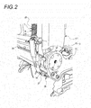
- FIG. 2 is a perspective view of the wire harness installing structure viewed from obliquely backward on the right of the vehicle seat illustrated in FIG. 1 .
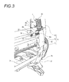
- FIG. 3 is a perspective view of the wire harness installing structure viewed from obliquely backward on the left of the vehicle seat illustrated in FIG. 1 .
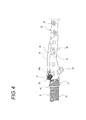
- FIG. 4 is a side view of a fixture used in a second fixing part in the wire harness installing structure illustrated in FIG. 3 .
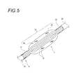
- FIG. 5 is a partially broken perspective view illustrating an outline configuration of a main part of the wire harness installing structure illustrated in FIG. 1 .
- a wire harness 5 is installed in a vehicle reclining seat 3.
- a lower end of a seat back structure 13 serving as a second structure is movably coupled to a rear end of a seat bottom structure 11 serving as a first structure.
- the seat bottom structure 11 is disposed substantially in horizontal direction.
- the seat back structure 13 extends upward from the rear end of the seat bottom structure 11.
- the rear end of the seat bottom structure 11 and the lower end of the seat back structure 13 are rotatably coupled to each other by a movable linking part 15 that couples those structures to each other by a rotating shaft 14.
- the seat back structure 13 is coupled to the seat bottom structure 11 by the movable linking part 15 so as to adjust the inclination angle thereof.
- the wire harness 5 basically has a structure in which a plurality of electric wires 21 and a cylindrical protective sheath 23 that holds the electric wires 21 in a bundle state are provided in a range other than the movable part installing section that will be described later as illustrated in FIG. 5 .
- the protective sheath 23 is formed of a corrugated tube.
- the wire harness installing structure 1 installs the wire harness 5 between two structures (the seat bottom structure 11 and the seat back structure 13) across the movable linking part 15.
- a movable part installing section 25 arranged in a predetermined length interval across the movable linking part 15 forms an non bundled part 26 in which the protective sheath 23 is peeled off (removed), and the respective electric wires 21 inside the protective sheath 23 are discretely movable.
- the movable part installing section 25 includes a stretchable protective member 27 that covers an outer periphery of the non bundled part 26 so as not to restrict the movability of the respective electric wires 21.
- the non bundled part 26 is in a state where the plurality of electric wires 21 are not bundled, and the electric wires are mutually freely movable, so that the non bundled part 26 can easily get into a flat shape, and can be easily bent.
- the stretchable protective member 27 is formed of a meshed resin tube having a stretch property.
- first fixing part 31 that fixes one end of the movable part installing section 25 to the seat bottom structure 11
- second fixing part 33 that fixes the other end of the movable part installing section 25 to the seat back structure 13.
- the first fixing part 31 is a bundling band that bundles the wire harness 5 into the seat bottom structure 11.
- the second fixing part 33 is a resin protector including a protector main body 34 having a U-shaped section into which the other end of the movable part installing section 25 can be inserted, and a cover 35 that openably covers an opened part of the protector main body 34.
- the protector main body 34 has a branch hole 34a that guides a part of the accommodated electric wires 21 laterally as a branch harness 29.
- the wire harness 5 is fixed to the second fixing part 33 by a bundling band 40.
- the protector main body 34 has an elastic engagement projection 36 that is engaged with a fitting hole provided in the seat back structure 13, and fixed to the seat back structure 13.
- the second fixing part 33 is fixed to the seat back structure 13 by engagement with the elastic engagement projection 36 or the bundle by the bundling band 40.
- the arrangement of the first fixing part 31 and the arrangement of the second fixing part 33 are set to match each other in a direction (in this embodiment, an axial direction of the rotating shaft 14 which is a width direction of the reclining seat 3) orthogonal to a relative movement direction (in this embodiment, a forward-backward direction of the vehicle) of the first fixing part 31 and the second fixing part 33 due to the mutual movability of the structures.
- the electric wires 21 can easily get into a flat shape, and can be easily bent.
- FIG. 6 is a diagram illustrating a bend state of the movable part installing section of the wire harness in a state where the seat back structure is reclined forward in the wire harness installing structure according to the first embodiment, in which FIG. 6(a) is a side view, FIG. 6(b) is a perspective view from obliquely forward of the vehicle seat, and FIG. 6(c) is a perspective view from obliquely backward.
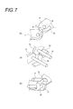
- FIG. 7 is a diagram illustrating the bend state of the movable part installing section of the wire harness in a state where the seat back structure is reclined backward in the wire harness installing structure according to the first embodiment, in which FIG. 7(a) is a side view, FIG. 7(b) is a perspective view from obliquely forward of the vehicle seat, and FIG. 7(c) is a perspective view from obliquely backward.
- the seat back structure 13 can be reclined forward from the state illustrated in FIGS. 6(a) to 6(c) , and the wire harness is also set to a sufficient length corresponding to the reclined state. Accordingly, in the state of FIGS. 6(a) to 6(c) , a surplus length of the wire harness occurs as compared with a state in which the seat back structure 13 is most forward inclined. However, the wire harness is flatly widened in the width direction of the vehicle in the movable part installing section so that the surplus length is absorbed.
- the movable part installing section 25 extending across the movable linking part 15 has high flexibility because the electric wires 21 are not mutually bundled by the protective sheath 23, and the respective electric wires 21 are freely movable. Accordingly, even if the bundle of electric wires 21 configuring the wire harness 5 is thick, since the movable part installing section 25 can be easily bent, the installing workability of the wire harness 5 to the reclining seat 3 can be improved.
- the wire harness 5 can be easily bent at the movable part installing section 25, the bend radius is not large, and the installation area under the reclining seat 3 can be saved in space.
- the wire harness 5 can be bent at the movable part installing section 25, no wide space is required for changing the installing direction, and the installation area under the reclining seat 3 can be saved in space.
- the stretchable protective member 27 equipped in the movable part installing section 25 appropriately suppresses the motion of the respective electric wires 21, and prevents the outer diameter of the movable part installing section 25 from being casually enlarged during the bending operation. Therefore, the stretchable protective member 27 contributes to the space saving of the installation area.
- the bend state of the movable part installing section 25 is changed with the mutually moving operation of the two structures 11 and 13.
- the mutually moving operation of the two structures 11 and 13 can be flexibly permitted.
- the electric wires 21 in the movable part installing section 25 is covered with the stretchable protective member 27, the electric wires 21 moving in a direction orthogonal to an extending direction of the electric wires 21 when the movable part installing section 25 is bent does not directly contact the structure around the reclining seat 3 so that the wire harness 5 can be prevented from being damaged.
- FIG. 8 is a diagram illustrating a bend state of a movable part installing section of the wire harness in a state where a seat back structure is reclined forward in a wire harness installing structure according to a second embodiment of the present invention, in which FIG. 8(a) is a side view, FIG. 8(b) is a perspective view from obliquely forward of the vehicle seat, and FIG. 8(c) is a perspective view from obliquely backward.
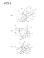
- FIG. 9 is a diagram illustrating the bend state of the movable part installing section of the wire harness in a state where a seat back structure is reclined backward in the wire harness installing structure according to the second embodiment of the present invention, in which FIG. 9(a) is a side view, FIG. 9(b) is a perspective view from obliquely forward of the vehicle seat, and FIG. 9(c) is a perspective view from obliquely backward.
- a wire harness installing structure 1A according to the second embodiment improves a part of the wire harness installing structure 1 described in the first embodiment.
- the improvement resides in that, as illustrated in FIG. 8(b) , the first fixing part 31 and the second fixing part 33 are displaced by an appropriate distance S in a direction (a width direction of the reclining seat 3) orthogonal to the relative moving direction (forward-backward direction of the vehicle) of the first fixing part 31 and the second fixing part 33 due to the mutual movability of the structures.
- configurations other than the configuration in which the first fixing part 31 and the second fixing part 33 are displaced by the distance S in the width direction of the reclining seat 3 may be common to those in the first embodiment, and the common configurations are denoted by the same reference numerals, and their description will be omitted.
- the movable part installing section 25 is not equipped with the protective sheath 23, and high in flexibility, the movable part installing section 25 can be easily bent following a displacement of the seat back structure 13. Also, because the bent part is twisted, and the surplus length can be absorbed, the movable part installing section 25 can be compactly bent.
- the movable part installing section 25 can be compactly bent. Also, because the movable part installing section 25 is high in flexibility, the movable part installing section 25 can be easily bent following the displacement of the seat back structure 13.
- the movable part installing section 25 deals with the relative movement by both of the simple bend and twist so that the surplus length absorption performance of the movable part installing section 25 can be improved. Accordingly, the allowance performance of the mutual movement of the two structures can be improved.
- the present invention is not limited to the above-mentioned embodiments, but may be appropriately freely deformed and improved.
- the materials, shapes, dimensions, numerical values, modes, quantities, and locations of the respective components in the above-mentioned embodiments are arbitrary and not restricted if they can achieve the present invention.
- an object to be installed is not limited to the vehicle reclining seat, but can be applied to various equipment and devices in which two structures are relatively movably coupled to each other by a movable linking part.
- the movable mode using the movable linking part is not also limited to the rotating structure described in the above embodiments.
- the movable mode can be also applied to a mechanism in which the movable linking part slidably couples two structures to each other, and the slide is permitted by bending the wire harness.
- the stretchable protective member 27 is not limited to the meshed resin tube described in the above embodiments, but a sheet or tape having the stretch property may be winded to the degree that does not regulate the movement of the electric wires.
- the present invention is not limited to the above-mentioned embodiments, but can be appropriately freely deformed or improved.
- the materials, shapes, dimensions, numerical values, modes, quantities, and locations of the respective components in the above-mentioned embodiments are arbitrary and not restricted if they can achieve the present invention.
- the present invention is based on Japanese Patent Application No. 2010-001291 filed on January 6, 2010 , and content thereof is incorporated herein by reference.
- the movable part installing section partially formed in the wire harness can be bent, twisted, or folded with a small radius to be installed, the installing workability can be improved. Also, when the movable part installing section is bent, the bend radius is not increased, and the movable part installing section can be folded and installed. Therefore, the installation area can be saved in space.
Landscapes
- Engineering & Computer Science (AREA)
- Mechanical Engineering (AREA)
- Aviation & Aerospace Engineering (AREA)
- Transportation (AREA)
- Seats For Vehicles (AREA)
- Details Of Indoor Wiring (AREA)
- Electric Cable Arrangement Between Relatively Moving Parts (AREA)
Applications Claiming Priority (2)
| Application Number | Priority Date | Filing Date | Title |
|---|---|---|---|
| JP2010001291A JP5489335B2 (ja) | 2010-01-06 | 2010-01-06 | ワイヤハーネス配索構造 |
| PCT/JP2011/050067 WO2011083807A1 (ja) | 2010-01-06 | 2011-01-05 | ワイヤハーネス配索構造 |
Publications (3)
| Publication Number | Publication Date |
|---|---|
| EP2523285A1 true EP2523285A1 (de) | 2012-11-14 |
| EP2523285A4 EP2523285A4 (de) | 2013-06-19 |
| EP2523285B1 EP2523285B1 (de) | 2016-09-28 |
Family
ID=44305544
Family Applications (1)
| Application Number | Title | Priority Date | Filing Date |
|---|---|---|---|
| EP11731805.5A Not-in-force EP2523285B1 (de) | 2010-01-06 | 2011-01-05 | Kabelrahmen-verkabelungsstruktur |
Country Status (5)
| Country | Link |
|---|---|
| US (1) | US20120261527A1 (de) |
| EP (1) | EP2523285B1 (de) |
| JP (1) | JP5489335B2 (de) |
| CN (1) | CN102668289B (de) |
| WO (1) | WO2011083807A1 (de) |
Cited By (1)
| Publication number | Priority date | Publication date | Assignee | Title |
|---|---|---|---|---|
| WO2021040730A1 (en) * | 2019-08-30 | 2021-03-04 | Safran Seats Usa Llc | Passenger seat wire routing |
Families Citing this family (8)
| Publication number | Priority date | Publication date | Assignee | Title |
|---|---|---|---|---|
| JP6546535B2 (ja) * | 2013-12-27 | 2019-07-17 | テイ・エス テック株式会社 | シート |
| US10294979B2 (en) * | 2015-10-23 | 2019-05-21 | Ts Tech Co., Ltd. | Vehicle seat |
| US11072267B2 (en) * | 2017-03-23 | 2021-07-27 | Ts Tech Co., Ltd. | Vehicle seat |
| JP2018181587A (ja) * | 2017-04-12 | 2018-11-15 | 矢崎総業株式会社 | 車両用配索材 |
| JP6681417B2 (ja) * | 2018-01-23 | 2020-04-15 | 矢崎総業株式会社 | 電気接続箱と保護部材の連結構造 |
| JP6836550B2 (ja) * | 2018-06-06 | 2021-03-03 | 矢崎総業株式会社 | プロテクタ |
| CN110176739B (zh) * | 2019-06-29 | 2024-05-17 | 国网湖北省电力有限公司随州供电公司 | 一种气压式电缆夹具 |
| JP7684550B2 (ja) * | 2021-03-25 | 2025-05-28 | テイ・エス テック株式会社 | 乗物用シート |
Family Cites Families (4)
| Publication number | Priority date | Publication date | Assignee | Title |
|---|---|---|---|---|
| FR2790337B1 (fr) * | 1999-02-05 | 2002-06-07 | Peugeot Citroen Automobiles Sa | Gaine de protection d'un faisceau electrique notamment d'un vehicule automobile et faisceau electrique equipe d'une telle gaine de protection |
| JP3570317B2 (ja) * | 1999-12-14 | 2004-09-29 | 住友電装株式会社 | 自動車用スライドドアのワイヤハーネス配索構造 |
| JP2006327240A (ja) * | 2005-05-23 | 2006-12-07 | Yazaki Corp | ハーネス配索構造 |
| US8772636B2 (en) * | 2008-06-25 | 2014-07-08 | Yazaki Corporation | Wire harness installation structure and wire harness-flattening band |
-
2010
- 2010-01-06 JP JP2010001291A patent/JP5489335B2/ja not_active Expired - Fee Related
-
2011
- 2011-01-05 WO PCT/JP2011/050067 patent/WO2011083807A1/ja not_active Ceased
- 2011-01-05 EP EP11731805.5A patent/EP2523285B1/de not_active Not-in-force
- 2011-01-05 CN CN201180004036.1A patent/CN102668289B/zh not_active Expired - Fee Related
- 2011-01-05 US US13/395,601 patent/US20120261527A1/en not_active Abandoned
Cited By (2)
| Publication number | Priority date | Publication date | Assignee | Title |
|---|---|---|---|---|
| WO2021040730A1 (en) * | 2019-08-30 | 2021-03-04 | Safran Seats Usa Llc | Passenger seat wire routing |
| US11919457B2 (en) | 2019-08-30 | 2024-03-05 | Safran Seats Usa Llc | Passenger seat wire routing |
Also Published As
| Publication number | Publication date |
|---|---|
| JP5489335B2 (ja) | 2014-05-14 |
| US20120261527A1 (en) | 2012-10-18 |
| JP2011142727A (ja) | 2011-07-21 |
| EP2523285A4 (de) | 2013-06-19 |
| WO2011083807A1 (ja) | 2011-07-14 |
| EP2523285B1 (de) | 2016-09-28 |
| CN102668289B (zh) | 2017-04-12 |
| CN102668289A (zh) | 2012-09-12 |
Similar Documents
| Publication | Publication Date | Title |
|---|---|---|
| EP2523285B1 (de) | Kabelrahmen-verkabelungsstruktur | |
| EP2298608B1 (de) | Vorrichtung umfassend ein Fahrzeug und einen Kabelbaum | |
| EP2302749B1 (de) | Kabelbaum-verlegestruktur | |
| US9401591B2 (en) | Wiring structure of electric wire | |
| EP2295294B1 (de) | Armstruktur | |
| JP5101981B2 (ja) | リンク用ハーネス配索構造 | |
| CN101689755A (zh) | 供电装置和使用该供电装置的线束配设结构 | |
| US7964795B2 (en) | Wire harness fixing structure | |
| CN102055122A (zh) | 线束 | |
| EP1108621A2 (de) | Kabelbaumsystem für eine Kraftfahrzeugschiebetür | |
| US20070084619A1 (en) | Power supply apparatus for sliding structure | |
| JP5235108B2 (ja) | ワイヤハーネス配索構造 | |
| US20180278036A1 (en) | Electric wire protecting member-equipped wire harness and slide wiring apparatus | |
| US7369381B2 (en) | Wiring harness holding device | |
| EP3674145B1 (de) | Kabelbaum | |
| JP2009095105A (ja) | リンク用ハーネスプロテクタ構造 | |
| US7057109B2 (en) | Guide protector for harness, wire-excessive portion absorbing structure therewith, and fixing method of guide protector for harness | |
| JP2011244569A (ja) | 電線の配索構造 | |
| WO2021200323A1 (ja) | プロテクタおよびワイヤハーネス | |
| JP2008174036A (ja) | 給電装置 | |
| JP6971525B2 (ja) | ワイヤーハーネスの配索構造 | |
| JP2004222449A (ja) | フラットケーブルの余長吸収装置 | |
| JP5264320B2 (ja) | 車両シートにおけるワイヤハーネス配索構造 | |
| JP4949954B2 (ja) | 給電装置のハーネス配索構造 | |
| JP2006180619A (ja) | 常時給電装置 |
Legal Events
| Date | Code | Title | Description |
|---|---|---|---|
| PUAI | Public reference made under article 153(3) epc to a published international application that has entered the european phase |
Free format text: ORIGINAL CODE: 0009012 |
|
| 17P | Request for examination filed |
Effective date: 20120312 |
|
| AK | Designated contracting states |
Kind code of ref document: A1 Designated state(s): AL AT BE BG CH CY CZ DE DK EE ES FI FR GB GR HR HU IE IS IT LI LT LU LV MC MK MT NL NO PL PT RO RS SE SI SK SM TR |
|
| DAX | Request for extension of the european patent (deleted) | ||
| A4 | Supplementary search report drawn up and despatched |
Effective date: 20130517 |
|
| RIC1 | Information provided on ipc code assigned before grant |
Ipc: H02G 11/00 20060101AFI20130513BHEP Ipc: B60R 16/02 20060101ALI20130513BHEP Ipc: B60N 2/44 20060101ALI20130513BHEP Ipc: H02G 3/04 20060101ALI20130513BHEP |
|
| 17Q | First examination report despatched |
Effective date: 20140714 |
|
| GRAP | Despatch of communication of intention to grant a patent |
Free format text: ORIGINAL CODE: EPIDOSNIGR1 |
|
| INTG | Intention to grant announced |
Effective date: 20151130 |
|
| GRAJ | Information related to disapproval of communication of intention to grant by the applicant or resumption of examination proceedings by the epo deleted |
Free format text: ORIGINAL CODE: EPIDOSDIGR1 |
|
| GRAP | Despatch of communication of intention to grant a patent |
Free format text: ORIGINAL CODE: EPIDOSNIGR1 |
|
| INTG | Intention to grant announced |
Effective date: 20160614 |
|
| GRAS | Grant fee paid |
Free format text: ORIGINAL CODE: EPIDOSNIGR3 |
|
| GRAA | (expected) grant |
Free format text: ORIGINAL CODE: 0009210 |
|
| AK | Designated contracting states |
Kind code of ref document: B1 Designated state(s): AL AT BE BG CH CY CZ DE DK EE ES FI FR GB GR HR HU IE IS IT LI LT LU LV MC MK MT NL NO PL PT RO RS SE SI SK SM TR |
|
| REG | Reference to a national code |
Ref country code: GB Ref legal event code: FG4D |
|
| RIN1 | Information on inventor provided before grant (corrected) |
Inventor name: SHOJI KAZUHIRO Inventor name: YAMAGUCHI ATSUYOSHI |
|
| REG | Reference to a national code |
Ref country code: CH Ref legal event code: EP |
|
| REG | Reference to a national code |
Ref country code: AT Ref legal event code: REF Ref document number: 833479 Country of ref document: AT Kind code of ref document: T Effective date: 20161015 |
|
| REG | Reference to a national code |
Ref country code: IE Ref legal event code: FG4D |
|
| REG | Reference to a national code |
Ref country code: DE Ref legal event code: R096 Ref document number: 602011030753 Country of ref document: DE |
|
| REG | Reference to a national code |
Ref country code: LT Ref legal event code: MG4D |
|
| PG25 | Lapsed in a contracting state [announced via postgrant information from national office to epo] |
Ref country code: FI Free format text: LAPSE BECAUSE OF FAILURE TO SUBMIT A TRANSLATION OF THE DESCRIPTION OR TO PAY THE FEE WITHIN THE PRESCRIBED TIME-LIMIT Effective date: 20160928 Ref country code: LT Free format text: LAPSE BECAUSE OF FAILURE TO SUBMIT A TRANSLATION OF THE DESCRIPTION OR TO PAY THE FEE WITHIN THE PRESCRIBED TIME-LIMIT Effective date: 20160928 Ref country code: RS Free format text: LAPSE BECAUSE OF FAILURE TO SUBMIT A TRANSLATION OF THE DESCRIPTION OR TO PAY THE FEE WITHIN THE PRESCRIBED TIME-LIMIT Effective date: 20160928 Ref country code: NO Free format text: LAPSE BECAUSE OF FAILURE TO SUBMIT A TRANSLATION OF THE DESCRIPTION OR TO PAY THE FEE WITHIN THE PRESCRIBED TIME-LIMIT Effective date: 20161228 Ref country code: HR Free format text: LAPSE BECAUSE OF FAILURE TO SUBMIT A TRANSLATION OF THE DESCRIPTION OR TO PAY THE FEE WITHIN THE PRESCRIBED TIME-LIMIT Effective date: 20160928 |
|
| REG | Reference to a national code |
Ref country code: NL Ref legal event code: MP Effective date: 20160928 |
|
| REG | Reference to a national code |
Ref country code: AT Ref legal event code: MK05 Ref document number: 833479 Country of ref document: AT Kind code of ref document: T Effective date: 20160928 |
|
| PG25 | Lapsed in a contracting state [announced via postgrant information from national office to epo] |
Ref country code: LV Free format text: LAPSE BECAUSE OF FAILURE TO SUBMIT A TRANSLATION OF THE DESCRIPTION OR TO PAY THE FEE WITHIN THE PRESCRIBED TIME-LIMIT Effective date: 20160928 Ref country code: NL Free format text: LAPSE BECAUSE OF FAILURE TO SUBMIT A TRANSLATION OF THE DESCRIPTION OR TO PAY THE FEE WITHIN THE PRESCRIBED TIME-LIMIT Effective date: 20160928 Ref country code: SE Free format text: LAPSE BECAUSE OF FAILURE TO SUBMIT A TRANSLATION OF THE DESCRIPTION OR TO PAY THE FEE WITHIN THE PRESCRIBED TIME-LIMIT Effective date: 20160928 Ref country code: GR Free format text: LAPSE BECAUSE OF FAILURE TO SUBMIT A TRANSLATION OF THE DESCRIPTION OR TO PAY THE FEE WITHIN THE PRESCRIBED TIME-LIMIT Effective date: 20161229 |
|
| PG25 | Lapsed in a contracting state [announced via postgrant information from national office to epo] |
Ref country code: EE Free format text: LAPSE BECAUSE OF FAILURE TO SUBMIT A TRANSLATION OF THE DESCRIPTION OR TO PAY THE FEE WITHIN THE PRESCRIBED TIME-LIMIT Effective date: 20160928 Ref country code: RO Free format text: LAPSE BECAUSE OF FAILURE TO SUBMIT A TRANSLATION OF THE DESCRIPTION OR TO PAY THE FEE WITHIN THE PRESCRIBED TIME-LIMIT Effective date: 20160928 |
|
| PG25 | Lapsed in a contracting state [announced via postgrant information from national office to epo] |
Ref country code: BE Free format text: LAPSE BECAUSE OF FAILURE TO SUBMIT A TRANSLATION OF THE DESCRIPTION OR TO PAY THE FEE WITHIN THE PRESCRIBED TIME-LIMIT Effective date: 20160928 Ref country code: SM Free format text: LAPSE BECAUSE OF FAILURE TO SUBMIT A TRANSLATION OF THE DESCRIPTION OR TO PAY THE FEE WITHIN THE PRESCRIBED TIME-LIMIT Effective date: 20160928 Ref country code: PT Free format text: LAPSE BECAUSE OF FAILURE TO SUBMIT A TRANSLATION OF THE DESCRIPTION OR TO PAY THE FEE WITHIN THE PRESCRIBED TIME-LIMIT Effective date: 20170130 Ref country code: PL Free format text: LAPSE BECAUSE OF FAILURE TO SUBMIT A TRANSLATION OF THE DESCRIPTION OR TO PAY THE FEE WITHIN THE PRESCRIBED TIME-LIMIT Effective date: 20160928 Ref country code: IS Free format text: LAPSE BECAUSE OF FAILURE TO SUBMIT A TRANSLATION OF THE DESCRIPTION OR TO PAY THE FEE WITHIN THE PRESCRIBED TIME-LIMIT Effective date: 20170128 Ref country code: AT Free format text: LAPSE BECAUSE OF FAILURE TO SUBMIT A TRANSLATION OF THE DESCRIPTION OR TO PAY THE FEE WITHIN THE PRESCRIBED TIME-LIMIT Effective date: 20160928 Ref country code: SK Free format text: LAPSE BECAUSE OF FAILURE TO SUBMIT A TRANSLATION OF THE DESCRIPTION OR TO PAY THE FEE WITHIN THE PRESCRIBED TIME-LIMIT Effective date: 20160928 Ref country code: ES Free format text: LAPSE BECAUSE OF FAILURE TO SUBMIT A TRANSLATION OF THE DESCRIPTION OR TO PAY THE FEE WITHIN THE PRESCRIBED TIME-LIMIT Effective date: 20160928 Ref country code: BG Free format text: LAPSE BECAUSE OF FAILURE TO SUBMIT A TRANSLATION OF THE DESCRIPTION OR TO PAY THE FEE WITHIN THE PRESCRIBED TIME-LIMIT Effective date: 20161228 Ref country code: CZ Free format text: LAPSE BECAUSE OF FAILURE TO SUBMIT A TRANSLATION OF THE DESCRIPTION OR TO PAY THE FEE WITHIN THE PRESCRIBED TIME-LIMIT Effective date: 20160928 |
|
| REG | Reference to a national code |
Ref country code: DE Ref legal event code: R097 Ref document number: 602011030753 Country of ref document: DE |
|
| PG25 | Lapsed in a contracting state [announced via postgrant information from national office to epo] |
Ref country code: IT Free format text: LAPSE BECAUSE OF FAILURE TO SUBMIT A TRANSLATION OF THE DESCRIPTION OR TO PAY THE FEE WITHIN THE PRESCRIBED TIME-LIMIT Effective date: 20160928 |
|
| PG25 | Lapsed in a contracting state [announced via postgrant information from national office to epo] |
Ref country code: DK Free format text: LAPSE BECAUSE OF FAILURE TO SUBMIT A TRANSLATION OF THE DESCRIPTION OR TO PAY THE FEE WITHIN THE PRESCRIBED TIME-LIMIT Effective date: 20160928 |
|
| PLBE | No opposition filed within time limit |
Free format text: ORIGINAL CODE: 0009261 |
|
| STAA | Information on the status of an ep patent application or granted ep patent |
Free format text: STATUS: NO OPPOSITION FILED WITHIN TIME LIMIT |
|
| REG | Reference to a national code |
Ref country code: CH Ref legal event code: PL |
|
| 26N | No opposition filed |
Effective date: 20170629 |
|
| GBPC | Gb: european patent ceased through non-payment of renewal fee |
Effective date: 20170105 |
|
| PG25 | Lapsed in a contracting state [announced via postgrant information from national office to epo] |
Ref country code: MC Free format text: LAPSE BECAUSE OF FAILURE TO SUBMIT A TRANSLATION OF THE DESCRIPTION OR TO PAY THE FEE WITHIN THE PRESCRIBED TIME-LIMIT Effective date: 20160928 |
|
| REG | Reference to a national code |
Ref country code: FR Ref legal event code: ST Effective date: 20170929 |
|
| PG25 | Lapsed in a contracting state [announced via postgrant information from national office to epo] |
Ref country code: LI Free format text: LAPSE BECAUSE OF NON-PAYMENT OF DUE FEES Effective date: 20170131 Ref country code: CH Free format text: LAPSE BECAUSE OF NON-PAYMENT OF DUE FEES Effective date: 20170131 Ref country code: FR Free format text: LAPSE BECAUSE OF NON-PAYMENT OF DUE FEES Effective date: 20170131 |
|
| REG | Reference to a national code |
Ref country code: IE Ref legal event code: MM4A |
|
| PG25 | Lapsed in a contracting state [announced via postgrant information from national office to epo] |
Ref country code: GB Free format text: LAPSE BECAUSE OF NON-PAYMENT OF DUE FEES Effective date: 20170105 Ref country code: SI Free format text: LAPSE BECAUSE OF FAILURE TO SUBMIT A TRANSLATION OF THE DESCRIPTION OR TO PAY THE FEE WITHIN THE PRESCRIBED TIME-LIMIT Effective date: 20160928 Ref country code: LU Free format text: LAPSE BECAUSE OF NON-PAYMENT OF DUE FEES Effective date: 20170105 |
|
| PG25 | Lapsed in a contracting state [announced via postgrant information from national office to epo] |
Ref country code: IE Free format text: LAPSE BECAUSE OF NON-PAYMENT OF DUE FEES Effective date: 20170105 |
|
| PG25 | Lapsed in a contracting state [announced via postgrant information from national office to epo] |
Ref country code: MT Free format text: LAPSE BECAUSE OF NON-PAYMENT OF DUE FEES Effective date: 20170105 |
|
| PG25 | Lapsed in a contracting state [announced via postgrant information from national office to epo] |
Ref country code: AL Free format text: LAPSE BECAUSE OF FAILURE TO SUBMIT A TRANSLATION OF THE DESCRIPTION OR TO PAY THE FEE WITHIN THE PRESCRIBED TIME-LIMIT Effective date: 20160928 |
|
| PG25 | Lapsed in a contracting state [announced via postgrant information from national office to epo] |
Ref country code: HU Free format text: LAPSE BECAUSE OF FAILURE TO SUBMIT A TRANSLATION OF THE DESCRIPTION OR TO PAY THE FEE WITHIN THE PRESCRIBED TIME-LIMIT; INVALID AB INITIO Effective date: 20110105 |
|
| PG25 | Lapsed in a contracting state [announced via postgrant information from national office to epo] |
Ref country code: CY Free format text: LAPSE BECAUSE OF NON-PAYMENT OF DUE FEES Effective date: 20160928 |
|
| PG25 | Lapsed in a contracting state [announced via postgrant information from national office to epo] |
Ref country code: MK Free format text: LAPSE BECAUSE OF FAILURE TO SUBMIT A TRANSLATION OF THE DESCRIPTION OR TO PAY THE FEE WITHIN THE PRESCRIBED TIME-LIMIT Effective date: 20160928 |
|
| PG25 | Lapsed in a contracting state [announced via postgrant information from national office to epo] |
Ref country code: TR Free format text: LAPSE BECAUSE OF FAILURE TO SUBMIT A TRANSLATION OF THE DESCRIPTION OR TO PAY THE FEE WITHIN THE PRESCRIBED TIME-LIMIT Effective date: 20160928 |
|
| PGFP | Annual fee paid to national office [announced via postgrant information from national office to epo] |
Ref country code: DE Payment date: 20231128 Year of fee payment: 14 |
|
| REG | Reference to a national code |
Ref country code: DE Ref legal event code: R119 Ref document number: 602011030753 Country of ref document: DE |
|
| PG25 | Lapsed in a contracting state [announced via postgrant information from national office to epo] |
Ref country code: DE Free format text: LAPSE BECAUSE OF NON-PAYMENT OF DUE FEES Effective date: 20250801 |