EP2523314B1 - Verbessertes Zweiflüssigkeitenkühlsystem für einen elektrischen Motor - Google Patents
Verbessertes Zweiflüssigkeitenkühlsystem für einen elektrischen Motor Download PDFInfo
- Publication number
- EP2523314B1 EP2523314B1 EP12166243.1A EP12166243A EP2523314B1 EP 2523314 B1 EP2523314 B1 EP 2523314B1 EP 12166243 A EP12166243 A EP 12166243A EP 2523314 B1 EP2523314 B1 EP 2523314B1
- Authority
- EP
- European Patent Office
- Prior art keywords
- stator
- sleeve
- rotor
- cooling medium
- sealed chamber
- Prior art date
- Legal status (The legal status is an assumption and is not a legal conclusion. Google has not performed a legal analysis and makes no representation as to the accuracy of the status listed.)
- Active
Links
- 239000007788 liquid Substances 0.000 title claims description 29
- 238000001816 cooling Methods 0.000 title description 5
- 230000009977 dual effect Effects 0.000 title 1
- 239000002826 coolant Substances 0.000 claims description 58
- 238000000034 method Methods 0.000 claims description 5
- 239000007787 solid Substances 0.000 claims description 5
- 230000008859 change Effects 0.000 claims description 2
- 239000003989 dielectric material Substances 0.000 claims description 2
- 239000007791 liquid phase Substances 0.000 claims description 2
- 239000000463 material Substances 0.000 claims description 2
- 239000004020 conductor Substances 0.000 description 6
- 150000001875 compounds Chemical class 0.000 description 5
- 239000012782 phase change material Substances 0.000 description 5
- 239000000853 adhesive Substances 0.000 description 4
- 230000001070 adhesive effect Effects 0.000 description 4
- DNIAPMSPPWPWGF-UHFFFAOYSA-N Propylene glycol Chemical compound CC(O)CO DNIAPMSPPWPWGF-UHFFFAOYSA-N 0.000 description 3
- 101000755768 Thermoplasma acidophilum (strain ATCC 25905 / DSM 1728 / JCM 9062 / NBRC 15155 / AMRC-C165) L-rhamnose 1-dehydrogenase (NADP(+)) Proteins 0.000 description 2
- 230000007246 mechanism Effects 0.000 description 2
- 238000002844 melting Methods 0.000 description 2
- 230000008018 melting Effects 0.000 description 2
- 238000004804 winding Methods 0.000 description 2
- 238000013459 approach Methods 0.000 description 1
- 230000008901 benefit Effects 0.000 description 1
- 230000008030 elimination Effects 0.000 description 1
- 238000003379 elimination reaction Methods 0.000 description 1
- 238000005470 impregnation Methods 0.000 description 1
- 238000004519 manufacturing process Methods 0.000 description 1
- 238000012986 modification Methods 0.000 description 1
- 230000004048 modification Effects 0.000 description 1
- 239000012188 paraffin wax Substances 0.000 description 1
- 230000008569 process Effects 0.000 description 1
- XLYOFNOQVPJJNP-UHFFFAOYSA-N water Substances O XLYOFNOQVPJJNP-UHFFFAOYSA-N 0.000 description 1
Images
Classifications
-
- H—ELECTRICITY
- H02—GENERATION; CONVERSION OR DISTRIBUTION OF ELECTRIC POWER
- H02K—DYNAMO-ELECTRIC MACHINES
- H02K9/00—Arrangements for cooling or ventilating
- H02K9/19—Arrangements for cooling or ventilating for machines with closed casing and closed-circuit cooling using a liquid cooling medium, e.g. oil
- H02K9/197—Arrangements for cooling or ventilating for machines with closed casing and closed-circuit cooling using a liquid cooling medium, e.g. oil in which the rotor or stator space is fluid-tight, e.g. to provide for different cooling media for rotor and stator
-
- Y—GENERAL TAGGING OF NEW TECHNOLOGICAL DEVELOPMENTS; GENERAL TAGGING OF CROSS-SECTIONAL TECHNOLOGIES SPANNING OVER SEVERAL SECTIONS OF THE IPC; TECHNICAL SUBJECTS COVERED BY FORMER USPC CROSS-REFERENCE ART COLLECTIONS [XRACs] AND DIGESTS
- Y10—TECHNICAL SUBJECTS COVERED BY FORMER USPC
- Y10T—TECHNICAL SUBJECTS COVERED BY FORMER US CLASSIFICATION
- Y10T29/00—Metal working
- Y10T29/49—Method of mechanical manufacture
- Y10T29/49002—Electrical device making
- Y10T29/49009—Dynamoelectric machine
Definitions
- This disclosure generally relates to a liquid cooled electric motor. More particularly, this disclosure relates to an electric motor including different cooling mediums for cooling different parts of the electric motor.
- a liquid cooled electric motor or machine includes a cooling medium that flows within a gap between the stator and rotor.
- the cooling medium is typically electrically conductive and therefore, the cooling medium is separated from the stator by a sleeve disposed about the rotor. Heat from the stator winding is conducted from the stator through the sleeve and finally to the cooling medium within the sleeve and surrounding the rotor.
- a thermally conductive compound is provided between the sleeve and the stator to aid in thermal conduction from the stator to the sleeve. Gaps or voids in the thermally conductive compound reduce thermal conduction of heat generated by the stator to the cooling medium contained within the sleeve.
- EP-A-0543280 discloses an electric motor whose stator space is water-cooled.
- an electric machine comprising: a stator defining an inner cavity; a rotor rotatable about an axis within the inner cavity, the rotor separated from the stator by an annular gap; a sleeve disposed about the rotor and within the annular gap, the sleeve defining a first sealed chamber including the rotor; a first cooling medium disposed within the first sealed chamber; and a second cooling medium disposed outside of the first sealed chamber and about the stator, wherein an interface between the stator and the sleeve comprises a press fit and any voids between the sleeve and stator are filled with the second cooling medium.
- a method of installing an electric motor comprising the steps of: mounting a stator and rotor within a sealed housing, with the stator and rotor separated by an annular gap; providing a sleeve disposed about the rotor and within the annular gap; defining, by the sleeve, a first sealed chamber within which is disposed the rotor; filling the first sealed chamber with a first cooling medium; defining a second sealed chamber about the first sealed chamber containing the stator; filling the second sealed chamber with a second cooling medium comprising at least one of a solid and a liquid; and mounting the sealed housing to a structure and engaging a driven member of the electric motor with a desired device, wherein the stator is mounted to the sleeve by a press fit and any voids between the sleeve and stator are filled with the second cooling medium.
- a disclosed electric machine includes a rotor within a cavity defined within a stator.
- a liquid coolant is utilized to cool the stator and rotor.
- the example liquid coolant is flowed through a gap defined between the stator and the rotor.
- the example liquid coolant is electrically conductive and constrained to interact with only one of either the stator or the rotor.
- Thermal energy produced during operation of the electric machine is conducted through the sleeve disposed within the gap between the stator and the rotor into the liquid coolant.
- the sleeve is placed in thermal contact with the stator through a thermally conductive adhesive.
- voids that lack the thermally conductive material are present.
- a second coolant is provided that is contained within a second cavity disposed annularly about the first cavity.
- the second liquid coolant is of a different composition than the first liquid coolant.
- Heat produced by the stator creates a natural convective flow within the second coolant contained in the second cavity. Thermal energy is therefore transferred away from the gap by way of the first coolant flowing through the gap and against the sleeve and by natural convection of the second liquid coolant within the second cavity.
- the additional mechanism for transferring heat enhances electric machine operation and provides increased operational capacities.
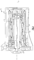
- an electric machine 10 includes a rotor 12 that rotates about an axis 14 within a cavity defined within a stator 18.
- the rotor 12 and stator 18 are supported within a housing 20.
- the example housing 20 also supports a pump 22 that is driven by rotation of the rotor 12.
- a liquid coolant 24 is utilized to cool the stator 18 and rotor 12.
- the example liquid coolant 24 is flowed through a gap 26 defined between the stator 18 and the rotor 12.
- the example liquid coolant 24 is electrically conductive and therefore must be separated and constrained to interact with only one of either the stator 18 or the rotor 12.
- the liquid coolant 24 comprises approximately 60% water and 40% propylene glycol by volume.
- other liquid coolants as are known are also within the contemplation of this invention.
- the example electric machine 10 is a motor driving a pump 22, other electric machines such as a generator or electric motor driving another device would also benefit from this disclosure.
- the liquid coolant 24 is contained within a cavity 16 defined about the rotor 12.
- a sleeve 28 is disposed within the gap 26 between the stator 18 and the rotor 12 to contain the electrically conductive coolant about the rotor 12 assembly.
- Thermal energy produced during operation of the electric machine 10 is conducted through the sleeve 28 disposed within the gap 26 between the stator 18 and the rotor 12 into the liquid coolant 24.
- the liquid coolant 24 flows about the rotor 12 and is constrained within the first cavity 16 defined by the sleeve 28.
- the sleeve 28 is sealed by o-rings 30 that are disposed on each end of the rotor 12. Because the liquid coolant 24 is constrained about the rotor 12, heat generated by the stator 18 must pass through the gap 26 and the sleeve 28 before reaching the liquid coolant 24.
- the sleeve 28 is placed in thermal contact with the stator 18 through a thermally conductive adhesive 32.
- This thermally conductive adhesive 32 provides the thermal path between the stator 18 and the sleeve 28.
- the thermally conductive adhesive 32 is an impregnation compound RHAD; however, other thermally conductive compounds as are known are also within the contemplation of this disclosure.
- the sleeve 28 is in thermal contact with the stator 18 through the thermally conductive material 32.
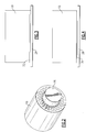
- thermally conductive material 32 is not evenly or consistently spread along the entire axial and annular length of the interface between the stator 18 and the sleeve 28.
- voids 34 that lack the thermally conductive material 32 are present.
- the voids 34 that do not include thermally conductive material 32 define an air gap between the stator 18 and the sleeve 28.
- This air gap is thermally inefficient and therefore does not conduct the thermal energy and heat generated by the stator 18 as efficiently as the thermally conductive material 32 between and into the sleeve 28 and finally into the liquid coolant 24 within the first cavity 16 defined within the sleeve 28. This results in overheated stator windings, thus reducing reliability of the electric machine.
- the example electric machine 10 includes a second coolant 38 contained within a second cavity 36 disposed annularly about the first cavity 16.
- the second liquid coolant 38 is of a different composition than the first liquid coolant 24.
- the second cavity 36 is defined by the sleeve 28. However the second cavity 36 is defined about an outer surface of the sleeve 28 in contrast to the first cavity 16 that is defined within an interior space of the sleeve 28.
- the first and second coolants 24, 38 are separated by the cavities 16, 36 defined by the sleeve 28.
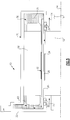
- the second coolant 38 is a dielectric material such as PAO or MIL-L-23699 oil and provides a thermally conductive interface between the stator 18 and the sleeve 28 in the voids 34. Voids 34 between the stator 18 and sleeve 28 are filled by the second coolant 38 and therefore, air gaps are no longer present between the sleeve 28 and stator 18 and heat may more efficiently transfer between the stator 18 and the sleeve 28. In addition, this method allows for elimination of the RHAD compound application process needed between the stator sleeve 28 and stator 18. The stator sleeve 28 can then be inserted by a press-fit (interference fit) within the stator assembly, thus reducing the cost of manufacturing.
- a press-fit interference fit
- Heat produced by the stator 18 creates a natural convective flow, shown schematically by arrows 40, within the second coolant 38 within the second cavity 36.
- the second coolant 38 flows outwardly from the hottest areas adjacent the sleeve 28 toward the outer portion of the housing 20. As the second coolant 38 cools, it flows back toward the interface between the sleeve 28 and stator 18.
- the natural convective flow 40 of the second liquid coolant 38 enhances thermal conduction and cooling of the electric machine 10.
- the second coolant 38 is a solid-liquid phase change material (PCM) such as organic paraffin.
- PCM solid-liquid phase change material
- the PCM is selected to have a melting point corresponding with operational temperatures of the electric machine 10. As the electric machine 10 approaches the selected melting point, the PCM in solid form will melt and fill any voids 34. As the electric machine 10 returns to normal operational temperatures, the PCM returns to solid form. The PCM will remain in solid form during operation of the electric machine 10 in normal temperature ranges.
- thermal energy is transferred away from the gap 26 by way of the first coolant 24 flowing through the gap 26 and against the sleeve 28 and by natural convection of the second liquid coolant 38 within the second cavity 36.
- the additional mechanism for transferring heat enhances electric machine operation and provides increased operational capacities.
Landscapes
- Engineering & Computer Science (AREA)
- Power Engineering (AREA)
- Motor Or Generator Cooling System (AREA)
Claims (9)
- Elektrische Maschine (10), Folgendes umfassend:einen Stator (18), der einen inneren Hohlraum definiert;einen Rotor (12), der drehbar um eine Achse in dem inneren Hohlraum ist, wobei der Rotor von dem Stator durch eine ringförmige Lücke (26) getrennt ist;eine Hülse (28), die um den Rotor und in der ringförmigen Lücke angeordnet ist, wobei die Hülse eine erste abgedichtete Kammer (16) definiert, die den Rotor beinhaltet;ein erstes Kühlmittel (24), das in der ersten abgedichteten Kammer angeordnet ist; undein zweites Kühlmittel (38), das außerhalb der ersten abgedichteten Kammer und um den Stator angeordnet ist,wobei eine Verbindung zwischen dem Stator (18) und der Hülse (28) eine Presspassung umfasst und alle Zwischenräume zwischen der Hülse und dem Stator mit dem zweiten Kühlmittel (38) gefüllt sind.
- Elektrische Maschine nach Anspruch 1, wobei das erste Kühlmittel (24) eine thermisch und elektrisch leitfähige Flüssigkeit umfasst.
- Elektrische Maschine nach Anspruch 1 oder 2, wobei das zweite Kühlmedium (38) ein dielektrisches Kühlmittel umfasst.
- Elektrische Maschine nach Anspruch 3, wobei das dielektrische Kühlmedium (38) eine Flüssigkeit umfasst, oder wobei das zweite Kühlmedium (38) ein fest-flüssiges Phasenwechselmaterial umfasst.
- Elektrische Maschine nach einem der vorstehenden Ansprüche, wobei der Stator (18) und der Rotor (12) in einem Gehäuse (20) angebracht sind, das einen Abschnitt einer zweiten abgedichteten Kammer (36) definiert, die um die erste abgedichtete Kammer (16) angeordnet ist.
- Elektrische Maschine nach Anspruch 5, wobei die zweite abgedichtete Kammer (36) ringförmig um die erste abgedichtete Kammer (16) angeordnet ist.
- Pumpenbaugruppe, Folgendes umfassend:eine Pumpe (22), die in einem Gehäuse (20) getragen wird; undeine elektrische Maschine (10) nach einem der vorstehenden Ansprüche, um die Pumpe anzutreiben, und wobei die elektrische Maschine in einem gemeinsamen Gehäuse getragen wird.
- Verfahren zum Installieren eines elektrischen Motors (10), wobei das Verfahren die folgenden Schritte umfasst:Befestigen eines Stators (18) und eines Rotors (12) in einem abgedichteten Gehäuse (20), wobei der Stator und der Rotor durch eine ringförmige Lücke (26) getrennt sind;Bereitstellen einer Hülse (28), die in der ringförmigen Lücke (26) um den Rotor angeordnet ist;Definieren einer ersten abgedichteten Kammer (16), in der der Rotor (12) angeordnet ist, durch die Hülse (28);Füllen der ersten abgedichteten Kammer (16) mit einem ersten Kühlmittel (24);Definieren einer zweiten abgedichteten Kammer (36) um die erste abgedichtete Kammer, die den Stator (18) enthält;Füllen der zweiten abgedichteten Kammer mit einem zweiten Kühlmittel (38), das mindestens eines von einem Feststoff und einer Flüssigkeit umfasst; undBefestigen des abgedichteten Gehäuses an einer Struktur und in Eingriff nehmen eines angetriebenen Teils des elektrischen Motors mit einer gewünschten Vorrichtung,wobei die Hülse durch eine Presspassung in den Stator eingefügt wird und alle Zwischenräume zwischen der Hülse und dem Stator mit dem zweiten Kühlmittel gefüllt sind.
- Verfahren nach Anspruch 8, wobei das zweite Kühlmittel (38) ein dielektrisches Material umfasst.
Applications Claiming Priority (1)
| Application Number | Priority Date | Filing Date | Title |
|---|---|---|---|
| US13/105,982 US20120286595A1 (en) | 2011-05-12 | 2011-05-12 | Enhanced dual liquid cooling system for electric motor |
Publications (3)
| Publication Number | Publication Date |
|---|---|
| EP2523314A2 EP2523314A2 (de) | 2012-11-14 |
| EP2523314A3 EP2523314A3 (de) | 2018-01-03 |
| EP2523314B1 true EP2523314B1 (de) | 2020-03-25 |
Family
ID=46084842
Family Applications (1)
| Application Number | Title | Priority Date | Filing Date |
|---|---|---|---|
| EP12166243.1A Active EP2523314B1 (de) | 2011-05-12 | 2012-04-30 | Verbessertes Zweiflüssigkeitenkühlsystem für einen elektrischen Motor |
Country Status (2)
| Country | Link |
|---|---|
| US (1) | US20120286595A1 (de) |
| EP (1) | EP2523314B1 (de) |
Cited By (1)
| Publication number | Priority date | Publication date | Assignee | Title |
|---|---|---|---|---|
| FR3131477A1 (fr) | 2021-12-28 | 2023-06-30 | Thales | Machine électrique intégrant des matériaux à changement de phase. |
Families Citing this family (19)
| Publication number | Priority date | Publication date | Assignee | Title |
|---|---|---|---|---|
| US9755482B2 (en) | 2013-03-12 | 2017-09-05 | Regal Beloit America, Inc. | Electric machine with liquid cooling and method of assembling |
| KR20150129829A (ko) * | 2013-03-14 | 2015-11-20 | 알리손 트랜스미션, 인크. | 하이브리드/전기 드라이브 모터용 통합 냉각부를 갖는 고정자 슬리브 |
| DE102013208029A1 (de) * | 2013-05-02 | 2014-11-06 | Siemens Aktiengesellschaft | Motorkühlung mit Phasen-Wechsel-Speicher |
| GB2518348A (en) | 2013-07-16 | 2015-03-25 | Aim Co Ltd | A rotor for an electric motor |
| GB2517410A (en) | 2013-07-16 | 2015-02-25 | Aim Co Ltd | A Stator and a Rotor for an Electric Motor |
| US20170077780A1 (en) * | 2014-06-02 | 2017-03-16 | Dresser-Rand Company | Stator can for improved rotordynamic stability |
| US9501752B2 (en) | 2014-06-11 | 2016-11-22 | Send A Job Inc. | Voice over internet protocol relay integration for field service management |
| DE102014221303B4 (de) * | 2014-10-13 | 2016-08-18 | Schaeffler Technologies AG & Co. KG | Elektrische Maschine mit integriertem Wärmepuffer sowie Antriebseinheit mit einer solchen elektronischen Maschine |
| DE102016111267A1 (de) | 2016-06-20 | 2017-12-21 | Cytec Zylindertechnik Gmbh | Elektrische Maschine für Werkzeugmaschinen |
| JP6834899B2 (ja) * | 2017-10-18 | 2021-02-24 | トヨタ自動車株式会社 | 回転電機コアの製造方法 |
| CN108397424A (zh) * | 2018-05-07 | 2018-08-14 | 王连春 | 一种水泵 |
| EP3588749A1 (de) * | 2018-06-29 | 2020-01-01 | Celeroton AG | Elektrische maschine |
| IT201800009201A1 (it) * | 2018-10-05 | 2020-04-05 | Ind Saleri Italo Spa | Gruppo pompa |
| CN109194037B (zh) * | 2018-10-30 | 2021-06-01 | 清华大学 | 一种隔离电机定子、转子所在空间的油冷电机 |
| WO2021050870A1 (en) * | 2019-09-13 | 2021-03-18 | Upwing Energy, LLC | Flow through magnetic drive system for artificial lift |
| US11387712B2 (en) * | 2019-09-13 | 2022-07-12 | GM Global Technology Operations LLC | Method to reduce oil shear drag in airgap |
| KR20230051193A (ko) * | 2020-07-13 | 2023-04-17 | 아이비스 인크. | 수소 연료공급 시스템 및 방법 |
| IT202000025315A1 (it) * | 2020-10-26 | 2022-04-26 | Ind Saleri Italo Spa | Gruppo pompa |
| US12184124B2 (en) | 2022-05-10 | 2024-12-31 | Hamilton Sundstrand Corporation | Combination of vacuum and positive pressure in motor stator potting process |
Family Cites Families (9)
| Publication number | Priority date | Publication date | Assignee | Title |
|---|---|---|---|---|
| US3285524A (en) * | 1964-01-13 | 1966-11-15 | Clarence H Dicus | Motor mill |
| DE4138268A1 (de) * | 1991-11-21 | 1993-05-27 | Klein Schanzlin & Becker Ag | Elektromotor |
| US5347188A (en) * | 1992-09-09 | 1994-09-13 | Sunstrand Corporation | Electric machine with enhanced liquid cooling |
| US5828148A (en) * | 1997-03-20 | 1998-10-27 | Sundstrand Corporation | Method and apparatus for reducing windage losses in rotating equipment and electric motor/generator employing same |
| DE19939598A1 (de) * | 1999-08-20 | 2001-03-08 | Magnet Motor Gmbh | Reluktanz-Elektromaschine |
| US7069979B2 (en) * | 2001-05-02 | 2006-07-04 | Lockheed Martin Corporation | Phase change heat sink for use in electrical solenoids and motors |
| WO2003084029A1 (en) * | 2002-04-01 | 2003-10-09 | Nissan Motor Co., Ltd. | Cooling structure for multi-shaft, multi-layer electric motor |
| FR2857521B1 (fr) * | 2003-07-11 | 2005-09-23 | Thales Sa | Refroidisseur d'un stator |
| SE529293C2 (sv) * | 2005-09-15 | 2007-06-26 | Lind Finance & Dev Ab | Kompressor samt förfarande |
-
2011
- 2011-05-12 US US13/105,982 patent/US20120286595A1/en not_active Abandoned
-
2012
- 2012-04-30 EP EP12166243.1A patent/EP2523314B1/de active Active
Non-Patent Citations (1)
| Title |
|---|
| None * |
Cited By (1)
| Publication number | Priority date | Publication date | Assignee | Title |
|---|---|---|---|---|
| FR3131477A1 (fr) | 2021-12-28 | 2023-06-30 | Thales | Machine électrique intégrant des matériaux à changement de phase. |
Also Published As
| Publication number | Publication date |
|---|---|
| EP2523314A3 (de) | 2018-01-03 |
| US20120286595A1 (en) | 2012-11-15 |
| EP2523314A2 (de) | 2012-11-14 |
Similar Documents
| Publication | Publication Date | Title |
|---|---|---|
| EP2523314B1 (de) | Verbessertes Zweiflüssigkeitenkühlsystem für einen elektrischen Motor | |
| US20200295628A1 (en) | Electric Machine Having A Cooling Device | |
| US20160006302A1 (en) | Arrangement for the stator cooling of an electric motor | |
| US11482908B1 (en) | System, method and apparatus for direct liquid-cooled axial flux electric machine with PCB stator | |
| KR101846604B1 (ko) | 전기 기계 냉각 시스템 및 방법 | |
| CN103858322B (zh) | 电机模块冷却系统和方法 | |
| CN103038983A (zh) | 电机冷却系统及方法 | |
| CN111200335A (zh) | 用于电机的温度控制组件 | |
| KR20130141511A (ko) | 전기 기계 스테이터용 냉각제 채널 | |
| WO2007149857A2 (en) | Electric motor with heat pipes | |
| KR20130141502A (ko) | 전기 기계 고정자를 위한 냉각제 채널 | |
| CN104662776A (zh) | 具有封装的端部线匝的电动机冷却系统 | |
| CN105048662A (zh) | 电机的散热 | |
| EP3109977B1 (de) | Elektrische drehmaschine und kühlsystem für elektrische drehmaschine | |
| CN109327091B (zh) | 用于电机的转子 | |
| CN118302941A (zh) | 转子组件以及包括转子组件的同步电机 | |
| US20150229186A1 (en) | Axial induction machine | |
| WO2014055298A1 (en) | Electric machine including a housing having materially integrally formed coolant channels and an outer sleeve | |
| EP2490323B1 (de) | Kühlung einer elektrischen Permanentmagnetmaschine | |
| CN116583676A (zh) | 泵组 | |
| EP3245711B1 (de) | Elektrische drehmaschine | |
| CN104160593B (zh) | 用于电动机械的转子的冷却装置 | |
| CN102104296A (zh) | 外转子直流无刷电动机散热结构 | |
| EP4062521B1 (de) | Leistungselektronikteil eines starter-generators ohne kommutator | |
| JP2015198515A (ja) | モータ構造体 |
Legal Events
| Date | Code | Title | Description |
|---|---|---|---|
| PUAI | Public reference made under article 153(3) epc to a published international application that has entered the european phase |
Free format text: ORIGINAL CODE: 0009012 |
|
| AK | Designated contracting states |
Kind code of ref document: A2 Designated state(s): AL AT BE BG CH CY CZ DE DK EE ES FI FR GB GR HR HU IE IS IT LI LT LU LV MC MK MT NL NO PL PT RO RS SE SI SK SM TR |
|
| AX | Request for extension of the european patent |
Extension state: BA ME |
|
| PUAL | Search report despatched |
Free format text: ORIGINAL CODE: 0009013 |
|
| AK | Designated contracting states |
Kind code of ref document: A3 Designated state(s): AL AT BE BG CH CY CZ DE DK EE ES FI FR GB GR HR HU IE IS IT LI LT LU LV MC MK MT NL NO PL PT RO RS SE SI SK SM TR |
|
| AX | Request for extension of the european patent |
Extension state: BA ME |
|
| RIC1 | Information provided on ipc code assigned before grant |
Ipc: H02K 9/197 20060101AFI20171130BHEP |
|
| STAA | Information on the status of an ep patent application or granted ep patent |
Free format text: STATUS: REQUEST FOR EXAMINATION WAS MADE |
|
| 17P | Request for examination filed |
Effective date: 20180703 |
|
| RBV | Designated contracting states (corrected) |
Designated state(s): AL AT BE BG CH CY CZ DE DK EE ES FI FR GB GR HR HU IE IS IT LI LT LU LV MC MK MT NL NO PL PT RO RS SE SI SK SM TR |
|
| GRAP | Despatch of communication of intention to grant a patent |
Free format text: ORIGINAL CODE: EPIDOSNIGR1 |
|
| STAA | Information on the status of an ep patent application or granted ep patent |
Free format text: STATUS: GRANT OF PATENT IS INTENDED |
|
| INTG | Intention to grant announced |
Effective date: 20191009 |
|
| GRAS | Grant fee paid |
Free format text: ORIGINAL CODE: EPIDOSNIGR3 |
|
| GRAA | (expected) grant |
Free format text: ORIGINAL CODE: 0009210 |
|
| STAA | Information on the status of an ep patent application or granted ep patent |
Free format text: STATUS: THE PATENT HAS BEEN GRANTED |
|
| AK | Designated contracting states |
Kind code of ref document: B1 Designated state(s): AL AT BE BG CH CY CZ DE DK EE ES FI FR GB GR HR HU IE IS IT LI LT LU LV MC MK MT NL NO PL PT RO RS SE SI SK SM TR |
|
| REG | Reference to a national code |
Ref country code: GB Ref legal event code: FG4D |
|
| REG | Reference to a national code |
Ref country code: AT Ref legal event code: REF Ref document number: 1249711 Country of ref document: AT Kind code of ref document: T Effective date: 20200415 Ref country code: IE Ref legal event code: FG4D |
|
| REG | Reference to a national code |
Ref country code: DE Ref legal event code: R096 Ref document number: 602012068683 Country of ref document: DE |
|
| PG25 | Lapsed in a contracting state [announced via postgrant information from national office to epo] |
Ref country code: NO Free format text: LAPSE BECAUSE OF FAILURE TO SUBMIT A TRANSLATION OF THE DESCRIPTION OR TO PAY THE FEE WITHIN THE PRESCRIBED TIME-LIMIT Effective date: 20200625 Ref country code: FI Free format text: LAPSE BECAUSE OF FAILURE TO SUBMIT A TRANSLATION OF THE DESCRIPTION OR TO PAY THE FEE WITHIN THE PRESCRIBED TIME-LIMIT Effective date: 20200325 Ref country code: RS Free format text: LAPSE BECAUSE OF FAILURE TO SUBMIT A TRANSLATION OF THE DESCRIPTION OR TO PAY THE FEE WITHIN THE PRESCRIBED TIME-LIMIT Effective date: 20200325 |
|
| PG25 | Lapsed in a contracting state [announced via postgrant information from national office to epo] |
Ref country code: BG Free format text: LAPSE BECAUSE OF FAILURE TO SUBMIT A TRANSLATION OF THE DESCRIPTION OR TO PAY THE FEE WITHIN THE PRESCRIBED TIME-LIMIT Effective date: 20200625 Ref country code: GR Free format text: LAPSE BECAUSE OF FAILURE TO SUBMIT A TRANSLATION OF THE DESCRIPTION OR TO PAY THE FEE WITHIN THE PRESCRIBED TIME-LIMIT Effective date: 20200626 Ref country code: SE Free format text: LAPSE BECAUSE OF FAILURE TO SUBMIT A TRANSLATION OF THE DESCRIPTION OR TO PAY THE FEE WITHIN THE PRESCRIBED TIME-LIMIT Effective date: 20200325 Ref country code: LV Free format text: LAPSE BECAUSE OF FAILURE TO SUBMIT A TRANSLATION OF THE DESCRIPTION OR TO PAY THE FEE WITHIN THE PRESCRIBED TIME-LIMIT Effective date: 20200325 Ref country code: HR Free format text: LAPSE BECAUSE OF FAILURE TO SUBMIT A TRANSLATION OF THE DESCRIPTION OR TO PAY THE FEE WITHIN THE PRESCRIBED TIME-LIMIT Effective date: 20200325 |
|
| REG | Reference to a national code |
Ref country code: NL Ref legal event code: MP Effective date: 20200325 |
|
| REG | Reference to a national code |
Ref country code: LT Ref legal event code: MG4D |
|
| PG25 | Lapsed in a contracting state [announced via postgrant information from national office to epo] |
Ref country code: NL Free format text: LAPSE BECAUSE OF FAILURE TO SUBMIT A TRANSLATION OF THE DESCRIPTION OR TO PAY THE FEE WITHIN THE PRESCRIBED TIME-LIMIT Effective date: 20200325 |
|
| PG25 | Lapsed in a contracting state [announced via postgrant information from national office to epo] |
Ref country code: PT Free format text: LAPSE BECAUSE OF FAILURE TO SUBMIT A TRANSLATION OF THE DESCRIPTION OR TO PAY THE FEE WITHIN THE PRESCRIBED TIME-LIMIT Effective date: 20200818 Ref country code: LT Free format text: LAPSE BECAUSE OF FAILURE TO SUBMIT A TRANSLATION OF THE DESCRIPTION OR TO PAY THE FEE WITHIN THE PRESCRIBED TIME-LIMIT Effective date: 20200325 Ref country code: SK Free format text: LAPSE BECAUSE OF FAILURE TO SUBMIT A TRANSLATION OF THE DESCRIPTION OR TO PAY THE FEE WITHIN THE PRESCRIBED TIME-LIMIT Effective date: 20200325 Ref country code: IS Free format text: LAPSE BECAUSE OF FAILURE TO SUBMIT A TRANSLATION OF THE DESCRIPTION OR TO PAY THE FEE WITHIN THE PRESCRIBED TIME-LIMIT Effective date: 20200725 Ref country code: RO Free format text: LAPSE BECAUSE OF FAILURE TO SUBMIT A TRANSLATION OF THE DESCRIPTION OR TO PAY THE FEE WITHIN THE PRESCRIBED TIME-LIMIT Effective date: 20200325 Ref country code: CZ Free format text: LAPSE BECAUSE OF FAILURE TO SUBMIT A TRANSLATION OF THE DESCRIPTION OR TO PAY THE FEE WITHIN THE PRESCRIBED TIME-LIMIT Effective date: 20200325 Ref country code: SM Free format text: LAPSE BECAUSE OF FAILURE TO SUBMIT A TRANSLATION OF THE DESCRIPTION OR TO PAY THE FEE WITHIN THE PRESCRIBED TIME-LIMIT Effective date: 20200325 Ref country code: EE Free format text: LAPSE BECAUSE OF FAILURE TO SUBMIT A TRANSLATION OF THE DESCRIPTION OR TO PAY THE FEE WITHIN THE PRESCRIBED TIME-LIMIT Effective date: 20200325 |
|
| REG | Reference to a national code |
Ref country code: AT Ref legal event code: MK05 Ref document number: 1249711 Country of ref document: AT Kind code of ref document: T Effective date: 20200325 |
|
| REG | Reference to a national code |
Ref country code: CH Ref legal event code: PL |
|
| PG25 | Lapsed in a contracting state [announced via postgrant information from national office to epo] |
Ref country code: MC Free format text: LAPSE BECAUSE OF FAILURE TO SUBMIT A TRANSLATION OF THE DESCRIPTION OR TO PAY THE FEE WITHIN THE PRESCRIBED TIME-LIMIT Effective date: 20200325 |
|
| REG | Reference to a national code |
Ref country code: DE Ref legal event code: R097 Ref document number: 602012068683 Country of ref document: DE |
|
| PG25 | Lapsed in a contracting state [announced via postgrant information from national office to epo] |
Ref country code: LI Free format text: LAPSE BECAUSE OF NON-PAYMENT OF DUE FEES Effective date: 20200430 Ref country code: IT Free format text: LAPSE BECAUSE OF FAILURE TO SUBMIT A TRANSLATION OF THE DESCRIPTION OR TO PAY THE FEE WITHIN THE PRESCRIBED TIME-LIMIT Effective date: 20200325 Ref country code: LU Free format text: LAPSE BECAUSE OF NON-PAYMENT OF DUE FEES Effective date: 20200430 Ref country code: DK Free format text: LAPSE BECAUSE OF FAILURE TO SUBMIT A TRANSLATION OF THE DESCRIPTION OR TO PAY THE FEE WITHIN THE PRESCRIBED TIME-LIMIT Effective date: 20200325 Ref country code: ES Free format text: LAPSE BECAUSE OF FAILURE TO SUBMIT A TRANSLATION OF THE DESCRIPTION OR TO PAY THE FEE WITHIN THE PRESCRIBED TIME-LIMIT Effective date: 20200325 Ref country code: CH Free format text: LAPSE BECAUSE OF NON-PAYMENT OF DUE FEES Effective date: 20200430 Ref country code: AT Free format text: LAPSE BECAUSE OF FAILURE TO SUBMIT A TRANSLATION OF THE DESCRIPTION OR TO PAY THE FEE WITHIN THE PRESCRIBED TIME-LIMIT Effective date: 20200325 |
|
| REG | Reference to a national code |
Ref country code: BE Ref legal event code: MM Effective date: 20200430 |
|
| PLBE | No opposition filed within time limit |
Free format text: ORIGINAL CODE: 0009261 |
|
| STAA | Information on the status of an ep patent application or granted ep patent |
Free format text: STATUS: NO OPPOSITION FILED WITHIN TIME LIMIT |
|
| PG25 | Lapsed in a contracting state [announced via postgrant information from national office to epo] |
Ref country code: PL Free format text: LAPSE BECAUSE OF FAILURE TO SUBMIT A TRANSLATION OF THE DESCRIPTION OR TO PAY THE FEE WITHIN THE PRESCRIBED TIME-LIMIT Effective date: 20200325 Ref country code: BE Free format text: LAPSE BECAUSE OF NON-PAYMENT OF DUE FEES Effective date: 20200430 |
|
| 26N | No opposition filed |
Effective date: 20210112 |
|
| PG25 | Lapsed in a contracting state [announced via postgrant information from national office to epo] |
Ref country code: IE Free format text: LAPSE BECAUSE OF NON-PAYMENT OF DUE FEES Effective date: 20200430 |
|
| PG25 | Lapsed in a contracting state [announced via postgrant information from national office to epo] |
Ref country code: SI Free format text: LAPSE BECAUSE OF FAILURE TO SUBMIT A TRANSLATION OF THE DESCRIPTION OR TO PAY THE FEE WITHIN THE PRESCRIBED TIME-LIMIT Effective date: 20200325 |
|
| PG25 | Lapsed in a contracting state [announced via postgrant information from national office to epo] |
Ref country code: TR Free format text: LAPSE BECAUSE OF FAILURE TO SUBMIT A TRANSLATION OF THE DESCRIPTION OR TO PAY THE FEE WITHIN THE PRESCRIBED TIME-LIMIT Effective date: 20200325 Ref country code: MT Free format text: LAPSE BECAUSE OF FAILURE TO SUBMIT A TRANSLATION OF THE DESCRIPTION OR TO PAY THE FEE WITHIN THE PRESCRIBED TIME-LIMIT Effective date: 20200325 Ref country code: CY Free format text: LAPSE BECAUSE OF FAILURE TO SUBMIT A TRANSLATION OF THE DESCRIPTION OR TO PAY THE FEE WITHIN THE PRESCRIBED TIME-LIMIT Effective date: 20200325 |
|
| PG25 | Lapsed in a contracting state [announced via postgrant information from national office to epo] |
Ref country code: MK Free format text: LAPSE BECAUSE OF FAILURE TO SUBMIT A TRANSLATION OF THE DESCRIPTION OR TO PAY THE FEE WITHIN THE PRESCRIBED TIME-LIMIT Effective date: 20200325 Ref country code: AL Free format text: LAPSE BECAUSE OF FAILURE TO SUBMIT A TRANSLATION OF THE DESCRIPTION OR TO PAY THE FEE WITHIN THE PRESCRIBED TIME-LIMIT Effective date: 20200325 |
|
| PGFP | Annual fee paid to national office [announced via postgrant information from national office to epo] |
Ref country code: FR Payment date: 20230321 Year of fee payment: 12 |
|
| PGFP | Annual fee paid to national office [announced via postgrant information from national office to epo] |
Ref country code: GB Payment date: 20230321 Year of fee payment: 12 |
|
| P01 | Opt-out of the competence of the unified patent court (upc) registered |
Effective date: 20230522 |
|
| PGFP | Annual fee paid to national office [announced via postgrant information from national office to epo] |
Ref country code: DE Payment date: 20230321 Year of fee payment: 12 |
|
| REG | Reference to a national code |
Ref country code: DE Ref legal event code: R119 Ref document number: 602012068683 Country of ref document: DE |
|
| GBPC | Gb: european patent ceased through non-payment of renewal fee |
Effective date: 20240430 |
|
| PG25 | Lapsed in a contracting state [announced via postgrant information from national office to epo] |
Ref country code: DE Free format text: LAPSE BECAUSE OF NON-PAYMENT OF DUE FEES Effective date: 20241105 |
|
| PG25 | Lapsed in a contracting state [announced via postgrant information from national office to epo] |
Ref country code: GB Free format text: LAPSE BECAUSE OF NON-PAYMENT OF DUE FEES Effective date: 20240430 |
|
| PG25 | Lapsed in a contracting state [announced via postgrant information from national office to epo] |
Ref country code: FR Free format text: LAPSE BECAUSE OF NON-PAYMENT OF DUE FEES Effective date: 20240430 |
|
| PG25 | Lapsed in a contracting state [announced via postgrant information from national office to epo] |
Ref country code: GB Free format text: LAPSE BECAUSE OF NON-PAYMENT OF DUE FEES Effective date: 20240430 Ref country code: FR Free format text: LAPSE BECAUSE OF NON-PAYMENT OF DUE FEES Effective date: 20240430 Ref country code: DE Free format text: LAPSE BECAUSE OF NON-PAYMENT OF DUE FEES Effective date: 20241105 |