EP2524609A2 - Mécanisme de verrouillage pour la retenue d'un verre de visière de protection - Google Patents
Mécanisme de verrouillage pour la retenue d'un verre de visière de protection Download PDFInfo
- Publication number
- EP2524609A2 EP2524609A2 EP12166875A EP12166875A EP2524609A2 EP 2524609 A2 EP2524609 A2 EP 2524609A2 EP 12166875 A EP12166875 A EP 12166875A EP 12166875 A EP12166875 A EP 12166875A EP 2524609 A2 EP2524609 A2 EP 2524609A2
- Authority
- EP
- European Patent Office
- Prior art keywords
- crown
- latch lever
- edge
- upper actuator
- face shield
- Prior art date
- Legal status (The legal status is an assumption and is not a legal conclusion. Google has not performed a legal analysis and makes no representation as to the accuracy of the status listed.)
- Granted
Links
Images






Classifications
-
- A—HUMAN NECESSITIES
- A42—HEADWEAR
- A42B—HATS; HEAD COVERINGS
- A42B3/00—Helmets; Helmet covers ; Other protective head coverings
- A42B3/04—Parts, details or accessories of helmets
- A42B3/18—Face protection devices
- A42B3/22—Visors
- A42B3/225—Visors with full face protection, e.g. for industrial safety applications
-
- A—HUMAN NECESSITIES
- A41—WEARING APPAREL
- A41D—OUTERWEAR; PROTECTIVE GARMENTS; ACCESSORIES
- A41D13/00—Professional, industrial or sporting protective garments, e.g. surgeons' gowns or garments protecting against blows or punches
- A41D13/05—Professional, industrial or sporting protective garments, e.g. surgeons' gowns or garments protecting against blows or punches protecting only a particular body part
- A41D13/11—Protective face masks, e.g. for surgical use, or for use in foul atmospheres
- A41D13/1184—Protective face masks, e.g. for surgical use, or for use in foul atmospheres with protection for the eyes, e.g. using shield or visor
Definitions
- the present specification relates to a protective face shield of the type having a crown and an arcuate transparent lens removably secured to the crown. More particularly, the specification relates to an improved latching mechanism for releasably securing the lens to the crown in order to facilitate the exchange of replacement lenses.
- Face shields of the general type herein described are known in the art.
- the prior art face shields typically comprise a crown for protecting the forehead area of the user, a transparent lens supported on the lower edge of the crown and extending down in front of the face of the user, and a head gear pivotably connected to the crown for supporting the crown and lens on the head of the user. Because of significant wear and tear on the lens in many environments, it is highly desirable to be able to replace a damaged or compromised lens.
- An improved protective face shield comprises a crown, a head gear pivotably attached to the crown, and an arcuate transparent lens removably secured to the crown with a latching mechanism have a wide paddle-shaped actuator that is easily accessible from the rearward edge of the crown.
- the crown has a shape contoured to conform to the shape of the forehead, a forward edge, a rearward edge and an opposing pair of rotational studs extending inwardly from an inner surface of the forward edge at opposing sides thereof.
- the upper peripheral edge of the lens includes an opposing pair of keyhole-shaped slots adjacent its opposing side edges.
- the keyhole-shaped slots are configured and arranged to receive and rotatably engage the rotational studs whereby the lens is received on the studs and rotatable upwardly about the studs into a groove in the forward edge of the crown.
- the latching mechanism is a latch lever having an upper actuator end, a lower engagement end and a fulcrum located therebetween.
- the lower engagement end of the latch includes a spaced pair of forwardly extending detents and the upper end is formed in the shape of a wide paddle to facilitate movement.
- the fulcrum is secured to an inner surface of the crown above the front edge so that the lower engagement end of the latch extends toward the front edge of the crown and the upper actuator end extends toward the rearward edge of the crown.
- the upper peripheral edge of the lens includes a pair of spaced openings configured and arranged to receive and releasably engage the forwardly extending detents on the engagement end of the latch lever.
- the latch lever is pivotably movable about the fulcrum between an engaged position wherein the detents on the lower engagement end project forwardly into engagement with the openings in the upper peripheral edge of the lens and a released position wherein the detents are disengaged from the opening.
- a spring is captured between the actuator end of the latch lever and the inner surface of the crown where the spring normally biases the latch lever into engagement with the lens.
- an objective is to provide an improved latching mechanism for the lens that will reduce the time, effort and complexity involved in the replacement of a damaged or compromised lens in a protective face shield.
- Another objective is to provide an improved latching mechanism that can be easily manipulated while wearing gloves.
- Still another objective is to provide a latching mechanism which is natural to use, easy to locate, and easily accessible.
- Yet another objective is to provide a latching mechanism which is accessible from the open rearward edge of the crown.
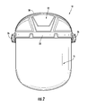
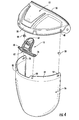
- a protective face shield generally indicated at 10 comprises a crown generally indicated at 12, a head gear generally indicated at 14 pivotably attached to the crown 12, and an arcuate transparent lens generally indicated at 16 removably secured to the crown 12 with a latching mechanism generally indicated at 18 have a wide paddle-shaped actuator that is easily accessible from the rearward edge of the crown 12.
- the head gear 14 has a well-known construction and is preferably molded from a resilient plastic material.
- the head gear 14 comprises a circular band 20 that encircles the head, a cross-band 22 extending over the top of the head, and a rack and pinion adjustment adjusting mechanism 24 for sizing the circular band 20 to a desired circumference and depth to achieve a comfortable fit on the user's head.
- the head gear 14 is pivotably mounted to the crown 12 by pivots 26 at opposing sides.
- the crown 12 is preferably a molded plastic component and has an arcuate shape contoured to conform to the shape of the forehead.
- the crown 12 includes a forward edge 28 adjacent the lower forehead area, and a rearward edge 30 adjacent to the top of the head.
- the crown 12 includes an outer depending wall 32 and an inner depending 34 wall spaced radially inwardly from the outer wall to define a channel 36 therebetween.
- the lens 16 is seated within the channel 36 when assembled with the crown 12.
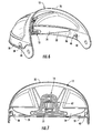
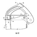
- the crown 12 includes an opposing pair of rotational studs 38, 40 (See Figs. 4 , 4a , 6, 7 , 13 , 14 ).
- the studs 38, 40 each have a cylindrical shaft 42, an outer head 44 and an inner cap 46.
- the studs 38, 40 extend through opposed openings 48, 50 ( Fig. 8 ) in the forward edge 28 of the crown 12 so that the shaft 42 and inner cap 46 extend inwardly toward the interior of the crown 12.
- the lens 16 is preferably molded from a transparent or translucent polycarbonate material. Other plastic materials and manufacturing methods for the lens are also contemplated within the scope of the disclosure.
- the upper peripheral edge 52 of the lens 16 includes an opposing pair of keyhole-shaped slots 54, 56 adjacent its opposing side edges.
- the keyhole-shaped slots 54, 56 each have a larger circular opening 58 at the rear and a narrower slot 60 extending forwardly from the circular opening 58.
- the circular openings 58 are configured and arranged to receive the caps 46 of the rotational studs 38, 40 on the crown 12, and then as the lens 16 is shifted rearwardly, the smaller diameter cylindrical shafts 42 slide into the narrower slots 60. Once engaged, the front portion of the lens 16 is rotatable upwardly about the studs 38, 40 where the upper peripheral edge 52 is received into the channel 36 in the forward edge 28 of the crown 12.
- the latching mechanism 18 comprises a latch lever 62 and a spring 64 for biasing the latch lever 62 to an engaged position.
- the latch lever 62 and spring 64 are integrally molded as a single unit from a resilient plastic material.
- the latch lever 62 includes an upper actuator end 66, a lower engagement end 68 and a fulcrum 70 located therebetween.
- the upper actuator end 66 of the latch lever 62 preferably has the shape of an enlarged paddle or pad so that it is easily engaged by a gloved hand of a user.
- the actuator end 66 is at least 1 inch wide, and more preferably is about 2 inches wide.
- the particular shape of the actuator end 66 is not particularly critical other than that it should have a width and depth that can be easily engaged by a gloved hand.
- the fulcrum 70 of the latch lever 70 is formed as a flexible tab 72 depending downwardly from a central portion of the lower portion of the upper actuator end 66. Referring to Fig. 10 , the fulcrum 70 is formed as a forwardly projecting post which is snap received into a mating slot 74 formed on the inner surface of the crown 12 (See Fig. 8 ).
- the lower engagement end 68 of the latch lever 62 is formed as a horizontally extending body supported by spaced arms 76, 78 which depend downwardly from outer portions of the lower edge of the upper actuator end 66.
- the horizontal engagement body 68 includes a spaced pair of forwardly extending detents 80, 82 which are configured and arranged to be received into corresponding openings 84, 86 in the upper peripheral edge 52 of the lens 16 (see Figs. 12 and 14 ).
- the fulcrum 70 is secured to the inner surface of the crown 12 above the front edge 28 so that the lower engagement end 68 of the latch lever 62 extends toward the front edge 28 of the crown 12 and the upper actuator end 66 extends toward the rearward edge 30 of the crown.
- the upper actuator end 66 is readily accessible from the rearward edge 30 of the crown 12.
- the upper peripheral edge of the lens includes a pair of spaced openings configured and arranged to receive and releasably engage the forwardly extending detents on the engagement end of the latch lever.
- latching mechanism While the illustrated embodiment of the latching mechanism is shown to utilize a pair of spaced detents and corresponding openings, it should be understood, that the latching mechanism can be implemented with a variety of detent and opening configurations so long as the engagement end includes at least one detent that engages with a corresponding opening.
- the latch lever is pivotably movable about the fulcrum between an engaged position, wherein the detents on the lower engagement end project forwardly into engagement with the openings in the upper peripheral edge of the lens and a released position wherein the detents are disengaged from the opening.
- a spring is captured between the upper actuator end of the latch lever and the inner surface of the crown where the spring normally biases the latch lever into engagement with the lens.
- the spring is integrally molded as part of the latch lever and comprises a leaf spring having a proximal end depending from the front surface of the upper actuating end of the latch lever. The spring extends forwardly where the terminal end thereof engages with the inner surface of the crown.
- a user may easily grasp the crown 12 with the user's thumb on the outside of the crown and the opposed fingers on the inside of the crown 12 and squeeze the actuator end 66 of the latch lever 62 toward the inside of the crown to disengage the lens 16. Since the lever 62 provides an effective moment arm, very little effort is needed to move the latch. With the other hand, the user can simultaneously grasp the bottom edge of the lens 16 and rotate the lens 16 out of the channel 36. Thereafter, the disengaged lens 16 can be easily disassembled from the rotational studs 38, 40 by simply sliding the lens 16 forwardly and sliding the lens 16 off of the studs 38, 40. A new lens is then installed in the reverse order. It can also be appreciated that all of the foregoing steps can be readily accomplished with gloved hands, thus making it convenient for the user to replace lenses in the field without much effort or distraction.
- an improved latching mechanism for the lens that will reduce the time, effort and complexity involved in the replacement of a damaged or compromised lens in a protective face shield, an improved latching mechanism that can be easily manipulated while wearing gloves, a latching mechanism which is natural to use, easy to locate, and easily accessible, and a latching mechanism which is accessible from the open rearward edge of the crown.
- the present latching mechanism is believed to represent a significant advancement in the art, which has substantial commercial merit.
Landscapes
- Health & Medical Sciences (AREA)
- General Health & Medical Sciences (AREA)
- Physical Education & Sports Medicine (AREA)
- Engineering & Computer Science (AREA)
- Textile Engineering (AREA)
- Lens Barrels (AREA)
- Eyeglasses (AREA)
- Helmets And Other Head Coverings (AREA)
Applications Claiming Priority (1)
| Application Number | Priority Date | Filing Date | Title |
|---|---|---|---|
| US13/113,019 US8336123B2 (en) | 2011-05-20 | 2011-05-20 | Latching mechanism for retention of face shield lens |
Publications (3)
| Publication Number | Publication Date |
|---|---|
| EP2524609A2 true EP2524609A2 (fr) | 2012-11-21 |
| EP2524609A3 EP2524609A3 (fr) | 2013-01-09 |
| EP2524609B1 EP2524609B1 (fr) | 2015-08-05 |
Family
ID=46026731
Family Applications (1)
| Application Number | Title | Priority Date | Filing Date |
|---|---|---|---|
| EP12166875.0A Active EP2524609B1 (fr) | 2011-05-20 | 2012-05-04 | Mécanisme de verrouillage pour la retenue d'un verre de visière de protection |
Country Status (3)
| Country | Link |
|---|---|
| US (1) | US8336123B2 (fr) |
| EP (1) | EP2524609B1 (fr) |
| CA (1) | CA2776493C (fr) |
Families Citing this family (58)
| Publication number | Priority date | Publication date | Assignee | Title |
|---|---|---|---|---|
| US20170031525A1 (en) | 2010-05-14 | 2017-02-02 | Racing Optics, Inc. | Touch screen shield |
| US8434167B2 (en) * | 2011-08-03 | 2013-05-07 | Honeywell International Inc. | Universal dual-pivot face shield assembly for a hard hat |
| KR101372886B1 (ko) * | 2012-05-31 | 2014-03-10 | 오토스테크 주식회사 | 안전모 착탈용 보안경 |
| US20140053307A1 (en) * | 2012-08-27 | 2014-02-27 | Polison Corporation | Protecting mask |
| US10757995B2 (en) * | 2014-03-07 | 2020-09-01 | Bell Sports, Inc. | Multi-body helmet construction with shield mounting |
| JP2017507256A (ja) * | 2014-03-07 | 2017-03-16 | ベル スポーツ, インコーポレイテッド | 遮蔽物を装着させたマルチボディヘルメット構造 |
| US20150335093A1 (en) * | 2014-05-20 | 2015-11-26 | Honeywell International, Inc. | Hard hat adapter |
| US9295297B2 (en) | 2014-06-17 | 2016-03-29 | Racing Optics, Inc. | Adhesive mountable stack of removable layers |
| EP3203869B1 (fr) | 2014-10-09 | 2020-03-25 | Gentex Corporation | Visière montée sur un casque |
| USD749795S1 (en) * | 2014-10-09 | 2016-02-16 | Artisent, Llc | Helmet mounted visor |
| US20170079364A1 (en) | 2014-11-20 | 2017-03-23 | Paulson Manufacturing Corporation | Protective face shield |
| USD831193S1 (en) * | 2015-08-13 | 2018-10-16 | Jsp Limited | Modular respirator with visor |
| ITUB20154868A1 (it) * | 2015-10-27 | 2017-04-27 | Kask Spa | Accessorio copri viso per caschi e casco munito di tale accessorio copri viso. |
| ITUB20155310A1 (it) | 2015-10-27 | 2017-04-27 | Kask Spa | Fascia poggia fronte per caschi e casco provvisto di tale fascia poggia fronte. |
| ITUB20155311A1 (it) | 2015-10-27 | 2017-04-27 | Kask Spa | Fascia poggia fronte per caschi e casco provvisto di tale fascia poggia fronte. |
| ITUB20154957A1 (it) | 2015-10-27 | 2017-04-27 | Kask Spa | Casco. |
| ITUB20154758A1 (it) * | 2015-10-27 | 2017-04-27 | Kask Spa | Fascia poggia fronte per caschi e casco provvisto di tale fascia poggia fronte. |
| CN105769439B (zh) * | 2016-03-01 | 2018-05-08 | 宁波吉欧光电科技有限公司 | 一种新型防护面屏 |
| US20170367423A1 (en) * | 2016-06-23 | 2017-12-28 | Six Flags Theme Parks, Inc. | Headband for virtual reality goggles |
| US20180184746A1 (en) * | 2016-10-31 | 2018-07-05 | Eric PLEBANI | Helmet construction |
| US10874159B1 (en) * | 2017-03-30 | 2020-12-29 | E.D. Bullard Company | Protective helmet with attachment mechanism for securing accessories |
| USD911625S1 (en) * | 2019-01-18 | 2021-02-23 | Gentex Corporation | Helmet mounted visor |
| WO2020160492A1 (fr) | 2019-02-01 | 2020-08-06 | Racing Optics, Inc. | Empilement thermoformé pour pare-brise au moyen d'un moule intégré façonnable |
| US11846788B2 (en) | 2019-02-01 | 2023-12-19 | Racing Optics, Inc. | Thermoform windshield stack with integrated formable mold |
| US11364715B2 (en) | 2019-05-21 | 2022-06-21 | Racing Optics, Inc. | Polymer safety glazing for vehicles |
| US12035765B2 (en) * | 2019-05-28 | 2024-07-16 | Honeywell International Inc. | Protective face shield assembly |
| US11648723B2 (en) | 2019-12-03 | 2023-05-16 | Racing Optics, Inc. | Method and apparatus for reducing non-normal incidence distortion in glazing films |
| US11912001B2 (en) | 2019-12-03 | 2024-02-27 | Ro Technologies, Llc | Method and apparatus for reducing non-normal incidence distortion in glazing films |
| US20210285661A1 (en) | 2020-03-10 | 2021-09-16 | Wolf Steel Ltd. | Heating and cooling appliance |
| US11548356B2 (en) | 2020-03-10 | 2023-01-10 | Racing Optics, Inc. | Protective barrier for safety glazing |
| US11219254B2 (en) * | 2020-03-13 | 2022-01-11 | Pabban Development, Inc. | Personal protection system and method |
| US20210392973A1 (en) * | 2020-04-02 | 2021-12-23 | Medspec Llc | Lightweight reusable face shield |
| DE102020008054A1 (de) * | 2020-04-07 | 2021-10-07 | Pfanner Schutzbekleidung Gmbh | Visier zur Befestigung an einer Kappe oder einem Stirnband oder einer Spange |
| USD899001S1 (en) * | 2020-04-08 | 2020-10-13 | Medspec Llc | Face shield |
| USD899700S1 (en) * | 2020-04-16 | 2020-10-20 | Medspec Llc | Face shield |
| US11399581B2 (en) * | 2020-04-17 | 2022-08-02 | Racing Optics, Inc. | Protective face shield attachable to headwear |
| US11147323B1 (en) * | 2020-04-17 | 2021-10-19 | Racing Optics, Inc. | Protective face shield attachable to headwear |
| KR102640597B1 (ko) * | 2020-04-24 | 2024-02-27 | 주식회사 에스폴리텍 | 페이스 쉴드 |
| WO2021226459A1 (fr) * | 2020-05-08 | 2021-11-11 | Milwaukee Electric Tool Corporation | Visière de protection pour casque de construction anti-impact |
| US11617403B2 (en) | 2020-05-26 | 2023-04-04 | Ford Global Technologies, Llc | Face shield manufacturing method and assembly |
| TWI730835B (zh) * | 2020-07-06 | 2021-06-11 | 安捷企業股份有限公司 | 防護面罩 |
| US10888130B1 (en) * | 2020-07-17 | 2021-01-12 | Pegasos One, LLC | Face shield for personal protection |
| US11206880B1 (en) * | 2020-07-17 | 2021-12-28 | Pegasos One, LLC | Face shield for personal protection |
| US11992070B2 (en) * | 2020-07-30 | 2024-05-28 | Illinois Tool Works Inc. | Face shield systems for securing removable face shield lenses |
| USD967545S1 (en) | 2020-07-30 | 2022-10-18 | Illinois Tool Works Inc. | Face shield |
| US11647799B2 (en) | 2020-08-03 | 2023-05-16 | Ford Global Technologies, Llc | Face shield assembly |
| US11751616B2 (en) * | 2020-08-31 | 2023-09-12 | Amdrecor, Inc. | Face shield and method of use |
| USD973969S1 (en) * | 2020-09-25 | 2022-12-27 | The United States Of America As Represented By The Secretary Of The Navy | Helmet face shield |
| USD964657S1 (en) * | 2020-12-31 | 2022-09-20 | Erb Industries, Inc. | Helmet with face shield |
| US11490667B1 (en) | 2021-06-08 | 2022-11-08 | Racing Optics, Inc. | Low haze UV blocking removable lens stack |
| US11709296B2 (en) | 2021-07-27 | 2023-07-25 | Racing Optics, Inc. | Low reflectance removable lens stack |
| US12140781B2 (en) | 2021-07-27 | 2024-11-12 | Laminated Film Llc | Low reflectance removable lens stack |
| US11307329B1 (en) | 2021-07-27 | 2022-04-19 | Racing Optics, Inc. | Low reflectance removable lens stack |
| US12527377B2 (en) | 2021-11-18 | 2026-01-20 | Husqvarna Ab | Reinforced face protection accessories for hard hats |
| US12162330B2 (en) | 2022-02-08 | 2024-12-10 | Ro Technologies, Llc | Multi-layer windshield film having progressive thickness layers |
| US12016419B2 (en) * | 2022-03-24 | 2024-06-25 | Paulson Manufacturing Corporation | Weight compensating bracket |
| US11933943B2 (en) | 2022-06-06 | 2024-03-19 | Laminated Film Llc | Stack of sterile peelable lenses with low creep |
| US11808952B1 (en) | 2022-09-26 | 2023-11-07 | Racing Optics, Inc. | Low static optical removable lens stack |
Family Cites Families (20)
| Publication number | Priority date | Publication date | Assignee | Title |
|---|---|---|---|---|
| US2360482A (en) | 1943-07-08 | 1944-10-17 | Mine Safety Appliances Co | Face shield |
| US2397722A (en) * | 1945-01-19 | 1946-04-02 | Fibre Metal Products Company | Face protective device |
| US2729820A (en) | 1953-01-19 | 1956-01-10 | Sellstrom Mfg Co | Safety headgear |
| US2763006A (en) * | 1953-10-12 | 1956-09-18 | Fendall Co | Face shield |
| US2829374A (en) | 1956-02-15 | 1958-04-08 | Chicago Eye Shield Company | Face shield and adjustable head band therefor |
| US3214767A (en) | 1962-12-20 | 1965-11-02 | Chicago Eye Shield Company | Face shield |
| US3380073A (en) * | 1965-12-02 | 1968-04-30 | James T. Mclaughlin | Protective device such as welder shield |
| US3686690A (en) * | 1968-11-19 | 1972-08-29 | American Safety Equip | Face shield |
| US3594816A (en) * | 1969-12-18 | 1971-07-27 | American Safety Equip | Safety helmet face shield |
| US4475254A (en) * | 1982-09-07 | 1984-10-09 | Bay William P | Visor attachment for helmet shield |
| DE3506495A1 (de) * | 1985-02-23 | 1986-09-04 | Artur 7060 Schorndorf Föhl | Sicherheitshelm |
| US4625341A (en) | 1985-07-18 | 1986-12-02 | Bell Helmets Inc. | Removably attachable shield for helmet visor |
| US4856109A (en) * | 1988-04-27 | 1989-08-15 | American Optical Corporation | Face protective device |
| US5673431A (en) | 1995-08-25 | 1997-10-07 | Dwight A. Marshall | Face mask safety shield |
| US5765223A (en) * | 1996-06-04 | 1998-06-16 | Mccausland; Mary L. | Face shield |
| KR100767702B1 (ko) * | 2006-03-24 | 2007-10-18 | 오토스테크 주식회사 | 다기능 보안면 |
| US20080276355A1 (en) * | 2007-05-11 | 2008-11-13 | Larry Lawrence | Anti-fouling faceshield |
| NZ568990A (en) * | 2008-06-06 | 2011-02-25 | Pacific Helmets Nz Ltd | Hinge system/visor attachment |
| US20110113535A1 (en) * | 2009-09-03 | 2011-05-19 | Lebel Stephane | Ballistic and Impact Protective System for Military Helmet Assembly |
| CN102370271A (zh) * | 2010-08-06 | 2012-03-14 | 深圳富泰宏精密工业有限公司 | 口罩 |
-
2011
- 2011-05-20 US US13/113,019 patent/US8336123B2/en active Active
-
2012
- 2012-05-04 EP EP12166875.0A patent/EP2524609B1/fr active Active
- 2012-05-08 CA CA2776493A patent/CA2776493C/fr active Active
Non-Patent Citations (1)
| Title |
|---|
| None |
Also Published As
| Publication number | Publication date |
|---|---|
| CA2776493A1 (fr) | 2012-11-20 |
| EP2524609B1 (fr) | 2015-08-05 |
| EP2524609A3 (fr) | 2013-01-09 |
| CA2776493C (fr) | 2019-06-18 |
| US8336123B2 (en) | 2012-12-25 |
| US20120291173A1 (en) | 2012-11-22 |
Similar Documents
| Publication | Publication Date | Title |
|---|---|---|
| CA2776493C (fr) | Dispositif de blocage pour hublot de masque facial | |
| EP2554068B1 (fr) | Ensemble écran facial universel à double pivot pour un casque | |
| EP3154386B1 (fr) | Visière amovible pour casque de protection | |
| EP0502272B1 (fr) | Casque muni d'une visière | |
| JP5690743B2 (ja) | 衝撃抵抗を強化されたメガネ | |
| US10226383B2 (en) | Welding helmet with removable neck guard | |
| JP5733858B2 (ja) | ヘルメットにおけるバイザ取り付け機構 | |
| US7162750B2 (en) | Detachable and rotatable clip | |
| US4312078A (en) | Helmet with pivotable visor | |
| EP1797783A1 (fr) | Dispositif pour soulever et abaisser d'une visière pare-soleil d'un casque de protection | |
| WO2018191100A1 (fr) | Casque de baseball à visière | |
| CA2050904A1 (fr) | Casque telephonique | |
| AU2474395A (en) | Clip-on sunglasses assembly for the brim of a hat | |
| JP6903245B1 (ja) | フェイスシールド | |
| JP2022124125A (ja) | フレーム、及び保護具 | |
| US4449255A (en) | Eyepiece for protective devices | |
| EP2432341B1 (fr) | Dispositif de déplacement pour casque permettant de déplacer un premier élément du casque par rapport à un second élément du casque | |
| JP3183123U (ja) | はさみ |
Legal Events
| Date | Code | Title | Description |
|---|---|---|---|
| PUAI | Public reference made under article 153(3) epc to a published international application that has entered the european phase |
Free format text: ORIGINAL CODE: 0009012 |
|
| 17P | Request for examination filed |
Effective date: 20120504 |
|
| AK | Designated contracting states |
Kind code of ref document: A2 Designated state(s): AL AT BE BG CH CY CZ DE DK EE ES FI FR GB GR HR HU IE IS IT LI LT LU LV MC MK MT NL NO PL PT RO RS SE SI SK SM TR |
|
| AX | Request for extension of the european patent |
Extension state: BA ME |
|
| PUAL | Search report despatched |
Free format text: ORIGINAL CODE: 0009013 |
|
| AK | Designated contracting states |
Kind code of ref document: A3 Designated state(s): AL AT BE BG CH CY CZ DE DK EE ES FI FR GB GR HR HU IE IS IT LI LT LU LV MC MK MT NL NO PL PT RO RS SE SI SK SM TR |
|
| AX | Request for extension of the european patent |
Extension state: BA ME |
|
| RIC1 | Information provided on ipc code assigned before grant |
Ipc: A41D 13/11 20060101ALI20121130BHEP Ipc: A42B 3/22 20060101AFI20121130BHEP |
|
| RIC1 | Information provided on ipc code assigned before grant |
Ipc: A42B 3/22 20060101AFI20121211BHEP Ipc: A41D 13/11 20060101ALI20121211BHEP |
|
| 17Q | First examination report despatched |
Effective date: 20140922 |
|
| GRAP | Despatch of communication of intention to grant a patent |
Free format text: ORIGINAL CODE: EPIDOSNIGR1 |
|
| INTG | Intention to grant announced |
Effective date: 20150319 |
|
| GRAS | Grant fee paid |
Free format text: ORIGINAL CODE: EPIDOSNIGR3 |
|
| GRAA | (expected) grant |
Free format text: ORIGINAL CODE: 0009210 |
|
| AK | Designated contracting states |
Kind code of ref document: B1 Designated state(s): AL AT BE BG CH CY CZ DE DK EE ES FI FR GB GR HR HU IE IS IT LI LT LU LV MC MK MT NL NO PL PT RO RS SE SI SK SM TR |
|
| REG | Reference to a national code |
Ref country code: GB Ref legal event code: FG4D |
|
| REG | Reference to a national code |
Ref country code: CH Ref legal event code: EP |
|
| REG | Reference to a national code |
Ref country code: AT Ref legal event code: REF Ref document number: 740156 Country of ref document: AT Kind code of ref document: T Effective date: 20150815 |
|
| REG | Reference to a national code |
Ref country code: IE Ref legal event code: FG4D |
|
| REG | Reference to a national code |
Ref country code: DE Ref legal event code: R096 Ref document number: 602012009265 Country of ref document: DE |
|
| REG | Reference to a national code |
Ref country code: AT Ref legal event code: MK05 Ref document number: 740156 Country of ref document: AT Kind code of ref document: T Effective date: 20150805 |
|
| RAP2 | Party data changed (patent owner data changed or rights of a patent transferred) |
Owner name: HONEYWELL INTERNATIONAL INC. |
|
| REG | Reference to a national code |
Ref country code: LT Ref legal event code: MG4D |
|
| REG | Reference to a national code |
Ref country code: NL Ref legal event code: MP Effective date: 20150805 |
|
| PG25 | Lapsed in a contracting state [announced via postgrant information from national office to epo] |
Ref country code: NO Free format text: LAPSE BECAUSE OF FAILURE TO SUBMIT A TRANSLATION OF THE DESCRIPTION OR TO PAY THE FEE WITHIN THE PRESCRIBED TIME-LIMIT Effective date: 20151105 Ref country code: GR Free format text: LAPSE BECAUSE OF FAILURE TO SUBMIT A TRANSLATION OF THE DESCRIPTION OR TO PAY THE FEE WITHIN THE PRESCRIBED TIME-LIMIT Effective date: 20151106 Ref country code: LV Free format text: LAPSE BECAUSE OF FAILURE TO SUBMIT A TRANSLATION OF THE DESCRIPTION OR TO PAY THE FEE WITHIN THE PRESCRIBED TIME-LIMIT Effective date: 20150805 Ref country code: LT Free format text: LAPSE BECAUSE OF FAILURE TO SUBMIT A TRANSLATION OF THE DESCRIPTION OR TO PAY THE FEE WITHIN THE PRESCRIBED TIME-LIMIT Effective date: 20150805 Ref country code: FI Free format text: LAPSE BECAUSE OF FAILURE TO SUBMIT A TRANSLATION OF THE DESCRIPTION OR TO PAY THE FEE WITHIN THE PRESCRIBED TIME-LIMIT Effective date: 20150805 |
|
| PG25 | Lapsed in a contracting state [announced via postgrant information from national office to epo] |
Ref country code: RS Free format text: LAPSE BECAUSE OF FAILURE TO SUBMIT A TRANSLATION OF THE DESCRIPTION OR TO PAY THE FEE WITHIN THE PRESCRIBED TIME-LIMIT Effective date: 20150805 Ref country code: IS Free format text: LAPSE BECAUSE OF FAILURE TO SUBMIT A TRANSLATION OF THE DESCRIPTION OR TO PAY THE FEE WITHIN THE PRESCRIBED TIME-LIMIT Effective date: 20151205 Ref country code: ES Free format text: LAPSE BECAUSE OF FAILURE TO SUBMIT A TRANSLATION OF THE DESCRIPTION OR TO PAY THE FEE WITHIN THE PRESCRIBED TIME-LIMIT Effective date: 20150805 Ref country code: PL Free format text: LAPSE BECAUSE OF FAILURE TO SUBMIT A TRANSLATION OF THE DESCRIPTION OR TO PAY THE FEE WITHIN THE PRESCRIBED TIME-LIMIT Effective date: 20150805 Ref country code: HR Free format text: LAPSE BECAUSE OF FAILURE TO SUBMIT A TRANSLATION OF THE DESCRIPTION OR TO PAY THE FEE WITHIN THE PRESCRIBED TIME-LIMIT Effective date: 20150805 Ref country code: SE Free format text: LAPSE BECAUSE OF FAILURE TO SUBMIT A TRANSLATION OF THE DESCRIPTION OR TO PAY THE FEE WITHIN THE PRESCRIBED TIME-LIMIT Effective date: 20150805 Ref country code: AT Free format text: LAPSE BECAUSE OF FAILURE TO SUBMIT A TRANSLATION OF THE DESCRIPTION OR TO PAY THE FEE WITHIN THE PRESCRIBED TIME-LIMIT Effective date: 20150805 Ref country code: PT Free format text: LAPSE BECAUSE OF FAILURE TO SUBMIT A TRANSLATION OF THE DESCRIPTION OR TO PAY THE FEE WITHIN THE PRESCRIBED TIME-LIMIT Effective date: 20151207 |
|
| PG25 | Lapsed in a contracting state [announced via postgrant information from national office to epo] |
Ref country code: NL Free format text: LAPSE BECAUSE OF FAILURE TO SUBMIT A TRANSLATION OF THE DESCRIPTION OR TO PAY THE FEE WITHIN THE PRESCRIBED TIME-LIMIT Effective date: 20150805 |
|
| REG | Reference to a national code |
Ref country code: FR Ref legal event code: PLFP Year of fee payment: 5 |
|
| PG25 | Lapsed in a contracting state [announced via postgrant information from national office to epo] |
Ref country code: DK Free format text: LAPSE BECAUSE OF FAILURE TO SUBMIT A TRANSLATION OF THE DESCRIPTION OR TO PAY THE FEE WITHIN THE PRESCRIBED TIME-LIMIT Effective date: 20150805 Ref country code: SK Free format text: LAPSE BECAUSE OF FAILURE TO SUBMIT A TRANSLATION OF THE DESCRIPTION OR TO PAY THE FEE WITHIN THE PRESCRIBED TIME-LIMIT Effective date: 20150805 Ref country code: CZ Free format text: LAPSE BECAUSE OF FAILURE TO SUBMIT A TRANSLATION OF THE DESCRIPTION OR TO PAY THE FEE WITHIN THE PRESCRIBED TIME-LIMIT Effective date: 20150805 Ref country code: IT Free format text: LAPSE BECAUSE OF FAILURE TO SUBMIT A TRANSLATION OF THE DESCRIPTION OR TO PAY THE FEE WITHIN THE PRESCRIBED TIME-LIMIT Effective date: 20150805 Ref country code: EE Free format text: LAPSE BECAUSE OF FAILURE TO SUBMIT A TRANSLATION OF THE DESCRIPTION OR TO PAY THE FEE WITHIN THE PRESCRIBED TIME-LIMIT Effective date: 20150805 |
|
| REG | Reference to a national code |
Ref country code: DE Ref legal event code: R097 Ref document number: 602012009265 Country of ref document: DE |
|
| PG25 | Lapsed in a contracting state [announced via postgrant information from national office to epo] |
Ref country code: RO Free format text: LAPSE BECAUSE OF FAILURE TO SUBMIT A TRANSLATION OF THE DESCRIPTION OR TO PAY THE FEE WITHIN THE PRESCRIBED TIME-LIMIT Effective date: 20150805 |
|
| PLBE | No opposition filed within time limit |
Free format text: ORIGINAL CODE: 0009261 |
|
| STAA | Information on the status of an ep patent application or granted ep patent |
Free format text: STATUS: NO OPPOSITION FILED WITHIN TIME LIMIT |
|
| 26N | No opposition filed |
Effective date: 20160509 |
|
| PG25 | Lapsed in a contracting state [announced via postgrant information from national office to epo] |
Ref country code: SI Free format text: LAPSE BECAUSE OF FAILURE TO SUBMIT A TRANSLATION OF THE DESCRIPTION OR TO PAY THE FEE WITHIN THE PRESCRIBED TIME-LIMIT Effective date: 20150805 Ref country code: BE Free format text: LAPSE BECAUSE OF NON-PAYMENT OF DUE FEES Effective date: 20160531 |
|
| PG25 | Lapsed in a contracting state [announced via postgrant information from national office to epo] |
Ref country code: BE Free format text: LAPSE BECAUSE OF FAILURE TO SUBMIT A TRANSLATION OF THE DESCRIPTION OR TO PAY THE FEE WITHIN THE PRESCRIBED TIME-LIMIT Effective date: 20150805 Ref country code: LU Free format text: LAPSE BECAUSE OF FAILURE TO SUBMIT A TRANSLATION OF THE DESCRIPTION OR TO PAY THE FEE WITHIN THE PRESCRIBED TIME-LIMIT Effective date: 20160504 |
|
| REG | Reference to a national code |
Ref country code: CH Ref legal event code: PL |
|
| PG25 | Lapsed in a contracting state [announced via postgrant information from national office to epo] |
Ref country code: CH Free format text: LAPSE BECAUSE OF NON-PAYMENT OF DUE FEES Effective date: 20160531 Ref country code: LI Free format text: LAPSE BECAUSE OF NON-PAYMENT OF DUE FEES Effective date: 20160531 |
|
| REG | Reference to a national code |
Ref country code: IE Ref legal event code: MM4A |
|
| REG | Reference to a national code |
Ref country code: FR Ref legal event code: PLFP Year of fee payment: 6 |
|
| PG25 | Lapsed in a contracting state [announced via postgrant information from national office to epo] |
Ref country code: IE Free format text: LAPSE BECAUSE OF NON-PAYMENT OF DUE FEES Effective date: 20160504 |
|
| REG | Reference to a national code |
Ref country code: FR Ref legal event code: PLFP Year of fee payment: 7 |
|
| PG25 | Lapsed in a contracting state [announced via postgrant information from national office to epo] |
Ref country code: CY Free format text: LAPSE BECAUSE OF FAILURE TO SUBMIT A TRANSLATION OF THE DESCRIPTION OR TO PAY THE FEE WITHIN THE PRESCRIBED TIME-LIMIT Effective date: 20150805 Ref country code: SM Free format text: LAPSE BECAUSE OF FAILURE TO SUBMIT A TRANSLATION OF THE DESCRIPTION OR TO PAY THE FEE WITHIN THE PRESCRIBED TIME-LIMIT Effective date: 20150805 Ref country code: HU Free format text: LAPSE BECAUSE OF FAILURE TO SUBMIT A TRANSLATION OF THE DESCRIPTION OR TO PAY THE FEE WITHIN THE PRESCRIBED TIME-LIMIT; INVALID AB INITIO Effective date: 20120504 |
|
| PG25 | Lapsed in a contracting state [announced via postgrant information from national office to epo] |
Ref country code: MC Free format text: LAPSE BECAUSE OF FAILURE TO SUBMIT A TRANSLATION OF THE DESCRIPTION OR TO PAY THE FEE WITHIN THE PRESCRIBED TIME-LIMIT Effective date: 20150805 Ref country code: TR Free format text: LAPSE BECAUSE OF FAILURE TO SUBMIT A TRANSLATION OF THE DESCRIPTION OR TO PAY THE FEE WITHIN THE PRESCRIBED TIME-LIMIT Effective date: 20150805 Ref country code: MK Free format text: LAPSE BECAUSE OF FAILURE TO SUBMIT A TRANSLATION OF THE DESCRIPTION OR TO PAY THE FEE WITHIN THE PRESCRIBED TIME-LIMIT Effective date: 20150805 Ref country code: MT Free format text: LAPSE BECAUSE OF NON-PAYMENT OF DUE FEES Effective date: 20160531 |
|
| PG25 | Lapsed in a contracting state [announced via postgrant information from national office to epo] |
Ref country code: BG Free format text: LAPSE BECAUSE OF FAILURE TO SUBMIT A TRANSLATION OF THE DESCRIPTION OR TO PAY THE FEE WITHIN THE PRESCRIBED TIME-LIMIT Effective date: 20150805 |
|
| PG25 | Lapsed in a contracting state [announced via postgrant information from national office to epo] |
Ref country code: AL Free format text: LAPSE BECAUSE OF FAILURE TO SUBMIT A TRANSLATION OF THE DESCRIPTION OR TO PAY THE FEE WITHIN THE PRESCRIBED TIME-LIMIT Effective date: 20150805 |
|
| REG | Reference to a national code |
Ref country code: DE Ref legal event code: R081 Ref document number: 602012009265 Country of ref document: DE Owner name: HONEYWELL SAFETY PRODUCTS USA, INC., WILMINGTO, US Free format text: FORMER OWNER: HONEYWELL INTERNATIONAL INC., MORRISTOWN, N.J., US |
|
| REG | Reference to a national code |
Ref country code: GB Ref legal event code: 732E Free format text: REGISTERED BETWEEN 20250515 AND 20250521 |
|
| PGFP | Annual fee paid to national office [announced via postgrant information from national office to epo] |
Ref country code: DE Payment date: 20250528 Year of fee payment: 14 |
|
| PGFP | Annual fee paid to national office [announced via postgrant information from national office to epo] |
Ref country code: GB Payment date: 20250520 Year of fee payment: 14 |
|
| PGFP | Annual fee paid to national office [announced via postgrant information from national office to epo] |
Ref country code: FR Payment date: 20250526 Year of fee payment: 14 |