EP2524662A2 - Port d'accès thoracique - Google Patents
Port d'accès thoracique Download PDFInfo
- Publication number
- EP2524662A2 EP2524662A2 EP20120168483 EP12168483A EP2524662A2 EP 2524662 A2 EP2524662 A2 EP 2524662A2 EP 20120168483 EP20120168483 EP 20120168483 EP 12168483 A EP12168483 A EP 12168483A EP 2524662 A2 EP2524662 A2 EP 2524662A2
- Authority
- EP
- European Patent Office
- Prior art keywords
- frame
- portions
- access assembly
- locking
- engagement
- Prior art date
- Legal status (The legal status is an assumption and is not a legal conclusion. Google has not performed a legal analysis and makes no representation as to the accuracy of the status listed.)
- Granted
Links
- 210000000115 thoracic cavity Anatomy 0.000 title description 17
- 210000001519 tissue Anatomy 0.000 claims description 52
- 210000004872 soft tissue Anatomy 0.000 claims description 4
- 239000012528 membrane Substances 0.000 description 37
- 238000000034 method Methods 0.000 description 19
- 230000003601 intercostal effect Effects 0.000 description 11
- 238000003780 insertion Methods 0.000 description 10
- 230000037431 insertion Effects 0.000 description 10
- 238000001356 surgical procedure Methods 0.000 description 8
- 238000003892 spreading Methods 0.000 description 4
- 239000000463 material Substances 0.000 description 3
- 238000002324 minimally invasive surgery Methods 0.000 description 3
- 238000011084 recovery Methods 0.000 description 3
- 239000000560 biocompatible material Substances 0.000 description 2
- 238000013461 design Methods 0.000 description 2
- 208000015181 infectious disease Diseases 0.000 description 2
- 208000014674 injury Diseases 0.000 description 2
- 238000012978 minimally invasive surgical procedure Methods 0.000 description 2
- 238000012986 modification Methods 0.000 description 2
- 230000004048 modification Effects 0.000 description 2
- 238000010899 nucleation Methods 0.000 description 2
- 238000003825 pressing Methods 0.000 description 2
- 230000008733 trauma Effects 0.000 description 2
- 206010067484 Adverse reaction Diseases 0.000 description 1
- 210000001015 abdomen Anatomy 0.000 description 1
- 238000004026 adhesive bonding Methods 0.000 description 1
- 230000006838 adverse reaction Effects 0.000 description 1
- 210000003484 anatomy Anatomy 0.000 description 1
- 238000004873 anchoring Methods 0.000 description 1
- 239000011324 bead Substances 0.000 description 1
- 210000001937 intercostal nerve Anatomy 0.000 description 1
- 239000000314 lubricant Substances 0.000 description 1
- 210000005036 nerve Anatomy 0.000 description 1
- 229920001296 polysiloxane Polymers 0.000 description 1
- 229920002635 polyurethane Polymers 0.000 description 1
- 239000004814 polyurethane Substances 0.000 description 1
- 230000002980 postoperative effect Effects 0.000 description 1
- 230000000284 resting effect Effects 0.000 description 1
- 230000000717 retained effect Effects 0.000 description 1
- 230000000451 tissue damage Effects 0.000 description 1
- 231100000827 tissue damage Toxicity 0.000 description 1
- 239000012780 transparent material Substances 0.000 description 1
- 238000012800 visualization Methods 0.000 description 1
- 238000003466 welding Methods 0.000 description 1
Images






Classifications
-
- A—HUMAN NECESSITIES
- A61—MEDICAL OR VETERINARY SCIENCE; HYGIENE
- A61B—DIAGNOSIS; SURGERY; IDENTIFICATION
- A61B17/00—Surgical instruments, devices or methods
- A61B17/02—Surgical instruments, devices or methods for holding wounds open, e.g. retractors; Tractors
- A61B17/0218—Surgical instruments, devices or methods for holding wounds open, e.g. retractors; Tractors for minimally invasive surgery
-
- A—HUMAN NECESSITIES
- A61—MEDICAL OR VETERINARY SCIENCE; HYGIENE
- A61B—DIAGNOSIS; SURGERY; IDENTIFICATION
- A61B17/00—Surgical instruments, devices or methods
- A61B17/02—Surgical instruments, devices or methods for holding wounds open, e.g. retractors; Tractors
- A61B17/0293—Surgical instruments, devices or methods for holding wounds open, e.g. retractors; Tractors with ring member to support retractor elements
-
- A—HUMAN NECESSITIES
- A61—MEDICAL OR VETERINARY SCIENCE; HYGIENE
- A61B—DIAGNOSIS; SURGERY; IDENTIFICATION
- A61B17/00—Surgical instruments, devices or methods
- A61B17/34—Trocars; Puncturing needles
- A61B17/3417—Details of tips or shafts, e.g. grooves, expandable, bendable; Multiple coaxial sliding cannulas, e.g. for dilating
- A61B17/3421—Cannulas
- A61B17/3423—Access ports, e.g. toroid shape introducers for instruments or hands
-
- A—HUMAN NECESSITIES
- A61—MEDICAL OR VETERINARY SCIENCE; HYGIENE
- A61B—DIAGNOSIS; SURGERY; IDENTIFICATION
- A61B17/00—Surgical instruments, devices or methods
- A61B2017/00367—Details of actuation of instruments, e.g. relations between pushing buttons, or the like, and activation of the tool, working tip, or the like
- A61B2017/00407—Ratchet means
-
- A—HUMAN NECESSITIES
- A61—MEDICAL OR VETERINARY SCIENCE; HYGIENE
- A61B—DIAGNOSIS; SURGERY; IDENTIFICATION
- A61B17/00—Surgical instruments, devices or methods
- A61B17/02—Surgical instruments, devices or methods for holding wounds open, e.g. retractors; Tractors
- A61B17/0218—Surgical instruments, devices or methods for holding wounds open, e.g. retractors; Tractors for minimally invasive surgery
- A61B2017/0225—Surgical instruments, devices or methods for holding wounds open, e.g. retractors; Tractors for minimally invasive surgery flexible, e.g. fabrics, meshes, or membranes
-
- A—HUMAN NECESSITIES
- A61—MEDICAL OR VETERINARY SCIENCE; HYGIENE
- A61B—DIAGNOSIS; SURGERY; IDENTIFICATION
- A61B17/00—Surgical instruments, devices or methods
- A61B17/02—Surgical instruments, devices or methods for holding wounds open, e.g. retractors; Tractors
- A61B2017/0237—Surgical instruments, devices or methods for holding wounds open, e.g. retractors; Tractors for heart surgery
-
- A—HUMAN NECESSITIES
- A61—MEDICAL OR VETERINARY SCIENCE; HYGIENE
- A61B—DIAGNOSIS; SURGERY; IDENTIFICATION
- A61B17/00—Surgical instruments, devices or methods
- A61B17/34—Trocars; Puncturing needles
- A61B17/3417—Details of tips or shafts, e.g. grooves, expandable, bendable; Multiple coaxial sliding cannulas, e.g. for dilating
- A61B17/3421—Cannulas
- A61B17/3423—Access ports, e.g. toroid shape introducers for instruments or hands
- A61B2017/3427—Access ports, e.g. toroid shape introducers for instruments or hands for intercostal space
-
- A—HUMAN NECESSITIES
- A61—MEDICAL OR VETERINARY SCIENCE; HYGIENE
- A61B—DIAGNOSIS; SURGERY; IDENTIFICATION
- A61B17/00—Surgical instruments, devices or methods
- A61B17/34—Trocars; Puncturing needles
- A61B2017/347—Locking means, e.g. for locking instrument in cannula
Definitions
- the present disclosure relates generally to devices and techniques for performing surgical procedures. More particularly, the present disclosure relates to an expandable access device for minimally invasive surgery.
- these procedures include laparoscopic procedures, which are generally performed within the confines of a patient's abdomen, and thoracic procedures, which are generally performed within a patient's chest cavity.
- surgical instruments typically include an elongated shaft with operative structure positioned at a distal end thereof, such as graspers, clip appliers, specimen retrieval bags, etc.
- the clinician creates an opening in the patient's body wall, oftentimes by using an obturator or trocar, and thereafter positions an access assembly within the opening.
- the access assembly includes a passageway extending therethrough to receive one or more of the above-mentioned surgical instruments for positioning within the internal work site, e.g. the body cavity.
- an access assembly is generally inserted into a space located between the patient's adjacent ribs that is known as the intercostal space, and then surgical instruments can be inserted into the internal work site through the passageway in the access assembly.
- a surgical access assembly for positioning within an opening in tissue.
- the surgical access assembly comprises an outer frame positionable outside a patient and defining an opening therein dimensioned to receive a surgical instrument therethrough.
- the outer frame has a first portion having a first engagement structure and a second portion having a second engagement structure, the first portion biased into locking engagement with the second portion such that the first engagement structure is in locking engagement with the second engagement structure.
- An inner member is positionable within a patient and a flexible member extends between the inner member and outer member and is operatively associated with the outer member.
- the first portion is movable to overcome the bias to move the first and second engagement structures to a disengaged position. In the disengaged position, at least one of the first and second portions is movable with respect to the other portion to adjust the tension on the flexible member to retract tissue.
- the access assembly includes a retaining frame having at least one spring to bias the first portion into locking engagement with the second portion.
- the first portion is biased in an axial direction along a longitudinal axis of the outer frame.
- the access assembly includes first and second links attached to the retaining frame and first portion, wherein movement of the first portion with respect to the retaining frame pivots the links to move the first engagement structure and the second engagement structure to the disengaged position.
- the first portion has an end wall and first and second arms extending therefrom and the second portion has an end wall and third and fourth arms extending therefrom, and pivoting of the links flexes the first and second arms radially inwardly from the third and fourth arms.
- the engagement structures can be positioned on the arms.
- the first engagement structure comprises a first set of teeth and the second engagement structure comprises a second set of teeth interlocking with the first set of teeth.
- the second engagement structure comprises a locking tab and the first engagement structure comprises an opening dimensioned to receive the locking tab.
- a retaining frame positioned external to the first and second portions can be provided.
- an end wall of the first portion is movable toward an end wall of the retaining frame to move the first and second engagement structure to the disengaged position and subsequently movable away from the end wall of the retaining frame to return the first and second portions into locking engagement.
- First and second pivotable link members can be provided connecting the retaining frame to the first portion. Movement of the first portion against the bias of a spring can pivot the links to a non-locking position to free the first and second portions for relative sliding movement.
- the present disclosure provides a surgical access assembly for positioning within an opening in tissue, the surgical access assembly comprising an outer tensioning member having an opening dimensioned and configured to receive a surgical instrument therethrough.
- the outer member includes first and second portions, the first and second portions having a locking position with respect to each other and a release position. The first and second portions are spring biased to the locking position.
- the assembly further includes a flexible member extending distally with respect to the outer tensioning member, the flexible member being spread upon movement of at least one of the first and second portions away from the other portion to retract soft tissue adjacent the opening in tissue.
- the assembly can further include in some embodiments a locking tab and an opening cooperating to interlock the first and second portions in the locking position.
- a retaining frame having a slot to receive the tab can be provided, wherein the first portion and retaining frame are relatively movable to move the first and second portions to the release position.
- a series of openings can be provided to selectively engage the tab to lock the first and second portions in one of several select spread positions.
- the locking tab can have an angled surface to facilitate movement out of the opening.
- a plurality of interlocking teeth are positioned on the first and second portions to interlock the first and second portions in the locking position.
- a plurality of links are connected to the first portion, wherein pivoting of the links moves the first portion to the release position.
- the present disclosure provides a surgical access assembly for positioning within an opening in tissue comprising an outer member positionable outside a patient and defining an opening therein dimensioned to receive a surgical instrument therethrough, and including first and second frame portions wherein at least one of the portions is movable, e.g., slidable, with respect to the other portion.
- An inner member is positionable within a patient and a flexible member extends between the inner member and outer member and is operatively associated with the outer member.
- a spring biased locking button cooperates with the second frame portion, and is movable to disengage from locking engagement with the second frame portion to enable relative movement of the first and second frame portions to tension the flexible member.
- the assembly further includes an intermediate frame positioned between the first and second frame portions, the intermediate frame having a recess to receive a spring to bias the locking button.
- the present disclosure provides a method of accessing an internal cavity of a patient comprising the steps of:
- the method may further comprise the step of moving at least one of surgical instrumentation and tissue specimen through the passageway and opening in the tissue.
- the method may also include the step of folding the inner member for insertion within the intercostal space into the internal cavity.
- Figure 1 is a perspective view of one embodiment of the access port of the present disclosure
- Figure 2 is an exploded perspective view of the access port of Figure 1 ;
- Figure 3 is a side view of the access port of Figure 1 ;
- Figure 4 is perspective front view illustrating a patient's skeletal structure with the surgical access port of Figure 1 positioned within the intercostal space defined between adjacent ribs in accordance with the present disclosure, the access port shown in an initial (non-expanded) position;
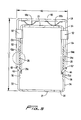
- FIG. 5 is a top view of the access port of Figure 1 in a first position
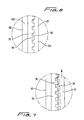
- Figure 6 is an enlarged view of the area of detail of Figure 5 ;
- Figure 7 is a view similar to Figure 6 illustrating disengagement of the teeth for movement of the frames
- Figure 8 is a top view similar to FIG. 5 illustrating release of the frames
- Figure 9 is a perspective view of an alternate embodiment of the access port of the present disclosure.
- Figure 9A is a side perspective view of a portion of the frames of the access assembly of Figure 9 ;
- FIG. 10 is an exploded view of the portion of the frames of FIG. 9A ;
- FIG. 11 is a top view of a portion of the frames of FIG. 9 illustrating engagement of the frames
- FIG. 12 is a cross-sectional view taken along line 12-12 of FIG. 11 ;
- FIG. 13 is a side view similar to FIG. 11 illustrating disengagement of the frames
- FIG. 14 is a view similar to FIG. 12 corresponding to the frame position of FIG. 13 ;
- FIG. 15 is a view similar to FIG. 14 showing movement of the frame to a more spread position
- FIG. 16 is perspective view similar to Figure 9A showing the frames in a more spread position
- Figure 17 is a side perspective view of a portion of the frames of an alternate embodiment of the access assembly of the present disclosure.
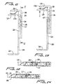
- Figure 18 is a cross-sectional view taken along line 18-18 of Figure 17 ;
- Figure 19 is a cross-sectional view similar to Figure 18 showing pressing of the release button.
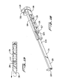
- Figure 20 is a cross-sectional view similar to Figure 19 showing movement of the frames after depression of the release button.
- proximal refers to the end of the access port, or component thereof, that is closer to the clinician and the term “distal” refers to the end that is further from the clinician, as is traditional and conventional in the art.
- distal refers to the end that is further from the clinician, as is traditional and conventional in the art.
- minimally invasive procedure is intended to include surgical procedures through small openings/incisions performed within a confined space such as the thoracic cavity.
- a first embodiment of the presently disclosed surgical access port is depicted as a thoracic port 10 that is configured and dimensioned for insertion into the intercostal space located between the adjacent ribs "R" ( FIG. 4 ) of a patient in order to allow for the insertion and manipulation of one or more surgical instruments within the thoracic cavity.
- access port 10 may be configured and dimensioned to provide access to a variety of other internal body cavities and/or tissues.
- Access port 10 may be formed from any suitable biocompatible material of strength suitable for the purpose described herein, including, but not being limited to, polymeric materials.
- the access port 10 is configured and dimensioned to extend into a body cavity, e.g., the thoracic cavity, through the intercostal space, and generally, with reference to Figures 1 and 2 , includes an outer or proximal frame 12 having a first or inside frame or frame portion 14, a second or outside frame or frame portion 16 and a release/locking frame or frame portion 18.
- a flexible member, e.g. membrane 70, is coupled to outer frame 12 and extends distally therefrom. The distal end of the flexible member 70 is attached to distal or inner member 50.
- the outer frame 12 is movable between various spread positions to widen the passageway for insertion of instrumentation and to retract tissue.
- portions 14 and 16 of frame 12 are relatively slidable to increase the distance between respective end walls 20, 22, and to increase the size of the opening 17 in the frame 12.
- the sliding of frame portions 14 and 16 applies tension to the flexible member 70 to retract tissue adjacent the incision in the patient to widen the access opening in the manner described below.
- the second portion 16 is slidable with respect to the first portion 14, it is also contemplated that the first portion 14 is slidable with respect to the second portion 16, or that both the first portion 14 and the second portion 16 are slidable.
- relatively slidable or slidable with respect to each other encompasses these alternatives.
- the frame 10 is substantially rectangular in shape with a substantially rectangular opening.
- shape frames and openings are also contemplated.
- shape is elongated, e.g. has a length greater than its width.
- first and second portions and/or members or frames contemplates an assembly of several (separate) components or a unitary assembly.
- Inner member 50 has an elongated opening 51 therethrough for passage of surgical instrumentation.
- the member 50 also has a nerve protecting wall or lip 52 extending along the opening 51, and preferably substantially surrounding the opening 51, and extending upwardly toward outer frame 12.
- the lip 52 facilitates attachment of the flexible membrane 70 thereto and can include proximally extending tabs (not shown) to facilitate such attachment.
- the member 50 is preferably composed of a substantially rigid material to provide anchoring of the access port while of sufficient flexibility to be bent or reconfigured for insertion as described below for fitting between the ribs of the intercostal space.
- the opening 51 is preferably non-circular in configuration, e.g. oval in configuration. Other configurations are also contemplated.
- the inner frame 50 long dimension is positioned transverse to the direction of movement of the outer frame 112. Consequently, the longer dimension of the opening 51 is transverse to the longer dimension of the passageway 17 of the outer frame 12.
- the outer frame 12 at least in its expanded position, has a length L1 exceeding its width W1 ( FIG. 5 ), the inner frame 50 has a length L2 exceeding its width W2 ( FIG. 2 ), and the lengthwise dimension of the outer frame 12 is aligned with the widthwise dimension of the inner frame 50.
- Flexible membrane 70 is generally funnel shaped, is coupled at its distal end 74 to lip 52 of inner member 50 and extends proximally therefrom.
- Proximal end 72 of flexible membrane 70 is coupled to an undersurface of end walls 20, 22 and isolates tissue surrounding access port 10 from the passageway extending therethrough, thus reducing the risk of tissue damage, seeding of cancerous cells, and/or infection during the surgical procedure. It can be attached by various methods such as welding, gluing or thermal bonding.
- flexible membrane 70 is configured for soft tissue retraction. It is also envisioned that flexible membrane 70 be of sufficient elasticity to permit retraction of a wide range of tissue thicknesses since there may be a wide range of tissue thicknesses among different patients.
- flexible membrane 70 is of sufficient strength to prevent accidental tearing and/or puncture by surgical instrumentation inserted through access port 100. Additionally, it is envisioned that flexible membrane 70 be made from a bio-compatible material to reduce the incidents of adverse reaction by a patient upon contact with the patient's tissue. Flexible membrane 70 may also be made of a transparent material to allow the surgeon to better visualize the surgical site and surrounding tissue. Flexible member 70 can be composed of polyurethane, although other materials such as silicone are also contemplated. It can be composed of a single member, a single member folded over and the edges attached forming a single seam, or alternatively two or more members attached together. For example, a two panel design with two seams or a four panel design with four seams, two on each side, can be utilized, with the flexible panels welded along the seam.
- Outer frame 12 is preferably sufficiently rigid to retain membrane 70 in a tensioned configuration. As frame 12 is expanded (spread), membrane 70 is tensioned and stretched radially outwardly to retract tissue and/or to expand the passageway 75 extending through membrane 70.
- first frame or frame portion 14 of outer frame 12 has arms 22 and 24 extending from end wall 20, preferably at substantially right angles thereto, although other angles are contemplated.
- Arm 22 has a series of teeth 26 along an outer side surface 22a thereof.
- arm 24 has a series of teeth 28 extending along an outer side surface 24a.
- the teeth 26, 28 face away from a central longitudinal axis of the frame 12.
- the teeth 26, 28 are shown extending along a portion of the arms 22, 24, however, a shorter or longer longitudinal arrangement of the teeth along the sidewalls is contemplated.
- Second frame or frame portion 16 of outer frame 12 has arms 32, 34 extending from end wall 23, preferably at substantially right angles thereto, although other angles are contemplated.
- Arm 32 has a series of teeth 36 along an inner surface 32b thereof.
- arm 34 has a series of teeth 38 extending along an inner surface 34b, facing teeth 36.
- the teeth 36, 38 face toward the central longitudinal axis of the frame 12 (and toward teeth 26, 28, respectively).
- the teeth 36, 38 are shown extending along a portion of the arms 32, 34, however a shorter or longer longitudinal arrangement of the teeth along the sidewalls is contemplated. Teeth 28 and 38 and teeth 26 and 36 interlock as described below.
- Upper surface 22c and lower surface 22d of arms 22, 24, respectively, of frame portion 14 each have a pin extending therefrom adjacent an end portion of the arm. More specifically, pin 29a extends upwardly or proximally from upper surface 22c to engage pivot hole 41a of link 40, and an opposing pin (not shown) extends downwardly or distally from lower surface 22d to engage pivot hole 47a of link 46. Similarly, upper surface 24c and lower surface 24d of arm 24 each have a pin extending therefreom adjacent an end portion of the arm. Pin 31a extends proximally from upper surface 24c and engages hole 45a of link 44 and an opposing pin (not shown) extends distally from bottom surface 24d to engage hole 49a of link 48. Links 40, 44, 46 and 48 also engage locking frame 18 described below.
- Locking/release frame 18 has an end wall 60 and arms 62, 64 extending therefrom, preferably at substantially right angles thereto, although other angles are contemplated.
- Locking or retaining frame 18 is positioned external of frames 14, 16 such that arm 62 extends along or outside outer surface of arms 32 and 22 and arm 64 extends along or outside outer surface of arms 34 and 24 of respective frames 16 and 14 (arms 32 and 34 are external of arms 22, 24, respectively).
- Pin 65 extending from upper or proximal surface 62a of arm 62 is received in pivot hole 41b of link 40.
- An opposing pin on the lower surface of arm 62 extends distally and is received in pivot hole 47b of link 46.
- Pin 67 extending from upper or proximal surface 64a of arm 64 is received in pivot hole 45b of link 44.
- An opposing pin on the lower surface of arm 64 extends distally and is received in pivot hole 49b of pivot link 48.
- Locking frame 18 has springs 69a, 69b extending from end wall 60 into contact with end wall 20 of frame portion 12 which bias frame 20 away from wall 60. In this biased position, the links 40, 44, 46 and 48 are at the angle shown in Figures 4 and 5 . This maintains the frame portions 14, 16 in the normally engaged position due to the engagement of the respective teeth (26, 36 and 28, 38). In order to spread the frames 14, 16 apart (move end walls 20 and 22 away from each other), frame 60 and frame 14 are squeezed together, overcoming the bias of the springs 69a, 69b, thereby causing the links 40, 44, 46 and 48 to move to the more straightened position of Figure 8 (e.g. substantially perpendicular to the longitudinal axis of the frame 12).
- the frame portions 14, 16 of the outer frame 12 can be moved apart to a desired spread position to expand and stretch the flexible membrane 70 and then the frame 14 is released, enabling it to return to a biased position and enabling the links 40, 44, 46, 48 to return to their original position so the arms 22, 24 return to their unflexed position of Figure 4 so the frames 14, 16 are locked in the select spread position by the interlocking of the teeth in the new position.
- the collars 90 and 92 help hold the frames 18 and 14 together.
- the first and second collars 90, 92 are substantially identical and each has a respective opening 94, 96 ( FIG. 2 ), therethrough for reception of the frames 18 and 14.
- the arms 62 and 22 of frames 18 and 14, respectively, are positioned through collar 90; the arms 64 and 24 of frames 18 and 14, respectively, are positioned through collar 92.
- arms 22, 24 of frame 14 in their normal position are in engagement with arms 32, 34, respectively, of frame 16 such that the engagement structures in the form of interlocking teeth engage.
- engagement structures in the form of textured surfaces of high friction can be utilized such as beads, ridges, domes and/or points which interlock with a textured surface of the other frame.
- a plurality of projections, e.g. domes or balls, can be provided to provide for engagement of the frame portions 14, 16 to help retain them in position.
- access port 10 is described for thoracic surgery, it being understood that it and the other access ports disclosed herein can be utilized in other procedures.
- an opening, or incision is made in the patient's outer tissue wall of the thoracic body cavity by conventional means.
- the incision is made between adjacent ribs "R" ( FIG. 4 ), extending along the intercostal space, and is relatively narrow and elongated.
- the inner member 50 is bent or reconfigured to reduce its transverse dimension for insertion through the patient's incision and into the body cavity. Note different sizes of access ports can also be used to accommodate different patients.
- the inner frame 50 is positioned within the body cavity adjacent the inner portion of the incision, with flexible membrane 70 extending through the incision to outside the patient's body and outer (upper) frame 12 (portions 14, 16) resting on the patient's skin.
- the outer frame 12 can now be expanded. Note the longitudinal axis of the inner frame 50 is substantially parallel to a long axis of the incision and the longitudinal axis of outer frame 12 is substantially transverse to a long axis of the incision, the longitudinal axis defined along the length of the respective frame which exceeds its width.
- flexible membrane 70 defines a funnel shape with frame 12 (portions 14, 16) retaining proximal end 72 of flexible membrane 70 while distal end 74 of flexible membrane 70 defines a smaller diameter due to the engagement of distal end 74 with the smaller inner frame 50. That is, since the width and length of outer frame 12 are greater than the width and length of the lip 52 of the inner member 50 to which the membrane 70 is attached at its distal end, a funnel shape is formed. In this initial position, lip 52 is configured to seat a rib "R" of a patient therein to protect the rib "R," the intercostal nerve, and surrounding tissue.
- lip 52 extends upwardly (proximally) into the opening in tissue adjacent the ribs "R," i.e., within the thoracic cavity. Additional cushioning (not shown) may be provided to provide further protection to the ribs and to surrounding tissue.
- Outward flexion of flexible membrane 70 due to expansion of the outer frame 12 expands the intercostal space, e.g. by spreading tissue adjacent the ribs, thus maximizing the passageway to the cavity, and giving access port 10 the maximum length.
- the respective teeth of frames 14 and 16 are engaged as shown in Figures 4 , 5 and 6 .
- teeth 26, 28, to flex inwardly toward a longitudinal axis of the frame 12 and away from respective arms 32, 34 to disengage from teeth 36, 38, respectively, of frame 16 (see Figures 7 and 8 ).
- This disengagement enables the user to grasp the frame 16, e.g. by grasping end wall 23 or arms 32 and 34, and moving it away from frame 14.
- This relative sliding movement tensions flexible membrane 70.
- the movement and more spread position of frame 16 are shown in phantom in Figure 8 . Note the tissue is spread transverse to the long axis of the incision.
- the surgeon releases the grasp of frame 14 and locking frame 18, allowing frame 14 to return to its normal position under the bias of springs 69a, 69b, as the links 40, 44, 46, 48 return to the their angled position of Figures 4 and 5 , with engagement surfaces moved from a non-engaged position to an engaged position to lock (secure) the first and second frames 14, 16 in the select position.
- This engagement of the engagement structures e.g. teeth 26, 36 and 28, 38
- access port 10 With access port 10 secured in the desired expanded position, surgical instrumentation may be inserted through passageway 17 (in outer frame 12), passageway 75 (in flexible member 70) and opening 51 in inner frame 50 to perform the surgical procedure within the body cavity.
- the low-profile configuration of access port 10, along the external surface of tissue, allows for greater access to the thoracic cavity and for greater manipulation of instrumentation disposed through the passageway.
- frame 14 and release frame 18 can once again be moved toward each other, to release the arms 22, 24, to allow them to move to their unlocked non-engaged position, thereby allowing the frame portions 14, 16 to be moved toward each other to untension flexible membrane 70.
- the surgeon may grasp inner member 50 to fold or reconfigure it to reduce its transverse dimension to remove it from the body cavity and through the incision.
- access port 10 is easily inserted, manipulated, and removed from a patient's body. Further, the access port 10 is minimally intrusive, flexible to conform to a patient's anatomy, and provides good visibility into the thoracic cavity. Additionally, the low-profile configuration of access port 10 is particularly advantageous, for example, in the removal, or retrieval, of tissue specimens from within the body.
- FIGS 9-16 illustrate an alternate embodiment of the access port of the present disclosure, designated by reference numeral 100.
- the access port 100 of Figure 9 is similar to access port 10 of Figure 1 in that it has an inner (distal) frame 150 and a flexible member (e.g. membrane) 170 identical to that of Figure 1 having openings to access the body cavity. Thus, details of frame 150 and member 170 are not repeated herein.
- the difference between the two ports 100 and 10 is the outer (proximal) frame which functions to tension and retain the flexible member 170.
- Outer frame 102 of access port 100 has a first frame or frame portion 104, a second frame or frame portion 106 and a locking release frame or frame portion 108.
- First and second frames 104, 106 are relatively slidable to tension membrane 170 as described below.
- Second frame 106 has an end wall 110 with side arms 112, 114, extending therefrom, preferably at substantially right angles thereto, although other angles are contemplated.
- a locking (engagement) tab 117 extends from a side surface 114a of arm 114, extending radially outwardly away from a longitudinal axis of the outer frame 102.
- a similar locking (engagement) tab extends from side surface 112a of arm 112, extending radially outwardly away from a longitudinal axis of frame 102.
- Engagement tab 117 includes an angled portion 117a, best shown in Figure 10 , to facilitate disengagement from a selected opening in the frames 104, 108 discussed below.
- First frame 104 includes a plurality of openings 124, 126 extending through a respective side wall 125a, 127a on each arm 125, 127. Openings 124, 126 are each configured and dimensioned to receive a locking tab of second frame 106. Arms 125, 127 extend from end wall 123, preferably at substantially right angles thereto, although other angles are contemplated.
- Locking or retaining frame 108 includes an end wall 130 and has springs 132a, 132b to bias frame 104 away from end wall 130. Arms 134, 136 extend from end wall 130, preferably at substantially right angles thereto, although other angles are contemplated. Locking frame 108 further includes a series of slots 138 formed in side wall 136a of arm 136. A similar series of slots is formed in the side wall of arm 134. The slots on each side wall are configured and dimensioned to receive the locking tabs of frame 106. Note the slots 138 have a transverse slot portion 138a to accommodate angled portion 117a of tab 117.
- the arms 134, 136 of locking frame 108 each have a channel 139, 140, respectively, to slidingly receive the arms of the frames 104, 106.
- locking frame 108 forms the outermost frame portion and first frame 104 is positioned between locking frame 108 and second frame 106, best shown in Figures 9 and 9A .
- First frame 104 is biased in a direction away from wall 130 of locking frame 108 by springs 132a, 132b.
- a first engagement tab 117 of frame 106 extends through a select opening 126 in arm 127 of frame 104 and a select slot 138 in arm 136 of locking frame 108.
- a second identical engagement locking tab on the opposing side of frame 106 extends through a select opening 124 in arm 125 of frame 104 and a select slot in arm 134 of locking frame 108. This maintains the frames 104, 106 in a locked/retained position.
- end walls 130 and 123 of frames 104, 108, respectively, are pressed together by the user, overcoming the bias of the springs 132a, 132b.
- frame 106 can be moved relative to frames 104, 106, frame 104 can be moved relative to frame 106, or both frames can be moved relative to each other.
- sliding movement or relative movement of the frames contemplates each of these.
- Surgical instrumentation can then be inserted through the passageway in access port 100 formed through outer frame 102, membrane 170 and inner frame 150 to access the cavity, e.g. the thoracic cavity.
- Figures 15 and 16 illustrate the tab 117 engaging the opening 126 of frame 104 and slot 138 of frame 108 corresponding to the most spread position of the frames 104, 106 as the tab 117 is engaged in the last of the openings and slots of frames 104, 108.
- the tab on the opposing side of frame 106 would likewise be locked in the corresponding last opening and slot of frames 104, 108.
- the tabs 117 can be locked within another opening and slot of the frames 104, 108. Note a different number of openings and slots than the number illustrated is also contemplated.
- Figures 17-20 illustrate another alternate embodiment of the present disclosure.
- a release/locking button is utilized to unlock the frames to allow sliding movement to spread the frames and tension the membrane.
- the embodiment of Figures 17-20 can be used with the flexible member 70 and inner frame 50 of Figure 1 and therefore the components are not shown in these Figures or further described herein.
- Outer frame 202 in this embodiment includes a first frame 204, a second frame 206 and a third locking frame 208 having a release button extending therefrom.
- Locking frame 208 is interposed between frames 204 and 206. Only portions of the frames are shown, it being understood that the frames are shaped similar to frames 104, 106 and 108 of access port 100.
- first frame or frame portion 204 is fixedly attached to locking frame 208.
- Locking frame 208 includes a cutout 210 to receive a spring 212 to bias a release button 214 into a locking position, radially outwardly from frame 208.
- Second frame or frame portion 206 has a plurality of longitudinally spaced openings 220 formed in a sidewall 222 configured and dimensioned to receive locking button 214.
- An identical locking button is formed on the opposing side of frame 208, seated in a cutout and biased outwardly by a spring as in button 214, to engage openings identical to openings 220 on the opposing side of frame 206.
- locking button 214 is spring biased outwardly to extend through one of the openings 220 on each side of second frame 206.
- Note movement of the locking frame 208 carries the first frame 204 which is secured thereto.
- the release button 222 on each side becomes aligned with the next opening 220 in frame 206, it moves into the opening 220 under the bias of the spring 212 to lock the frames 208, 206 in the select spread position. If further spreading of the frames to further tension the membrane is desired, the buttons 214 once again can be pressed in and the frames slid further apart, thus providing the incremental spreading of the frames and tensioning of the membrane.
- locking button 214 is pressed inwardly to release frame 206 for relative sliding movement of locking frame 208 and second frame 206 toward each other, i.e., move end wall 209 of locking frame 208 and end wall 225 of frame 206 toward each other.
- flexible membranes described herein may be coated with a lubricant, or gel, to aid in the insertion and removal of surgical instrumentation and/or tissue specimens from the access port.
Landscapes
- Health & Medical Sciences (AREA)
- Life Sciences & Earth Sciences (AREA)
- Surgery (AREA)
- Heart & Thoracic Surgery (AREA)
- Engineering & Computer Science (AREA)
- Biomedical Technology (AREA)
- Nuclear Medicine, Radiotherapy & Molecular Imaging (AREA)
- Medical Informatics (AREA)
- Molecular Biology (AREA)
- Animal Behavior & Ethology (AREA)
- General Health & Medical Sciences (AREA)
- Public Health (AREA)
- Veterinary Medicine (AREA)
- Pathology (AREA)
- Surgical Instruments (AREA)
Applications Claiming Priority (2)
| Application Number | Priority Date | Filing Date | Title |
|---|---|---|---|
| US201161487867P | 2011-05-19 | 2011-05-19 | |
| US13/445,118 US9039610B2 (en) | 2011-05-19 | 2012-04-12 | Thoracic access port |
Publications (3)
| Publication Number | Publication Date |
|---|---|
| EP2524662A2 true EP2524662A2 (fr) | 2012-11-21 |
| EP2524662A3 EP2524662A3 (fr) | 2012-12-12 |
| EP2524662B1 EP2524662B1 (fr) | 2017-04-12 |
Family
ID=46177343
Family Applications (1)
| Application Number | Title | Priority Date | Filing Date |
|---|---|---|---|
| EP12168483.1A Not-in-force EP2524662B1 (fr) | 2011-05-19 | 2012-05-18 | Port d'accès thoracique |
Country Status (3)
| Country | Link |
|---|---|
| US (2) | US9039610B2 (fr) |
| EP (1) | EP2524662B1 (fr) |
| CA (1) | CA2776190A1 (fr) |
Cited By (3)
| Publication number | Priority date | Publication date | Assignee | Title |
|---|---|---|---|---|
| EP2601898A3 (fr) * | 2011-12-07 | 2013-12-18 | Covidien LP | Port d'accès thoracique |
| EP3852647A4 (fr) * | 2018-09-17 | 2022-07-06 | Cestero, Ramon Francisco | Écarteur chirurgical à verrouillage réglable |
| US12426870B2 (en) | 2021-01-03 | 2025-09-30 | Advanced Surgical Retractor Systems, Inc. | Surgical retractor |
Families Citing this family (12)
| Publication number | Priority date | Publication date | Assignee | Title |
|---|---|---|---|---|
| US9039610B2 (en) | 2011-05-19 | 2015-05-26 | Covidien Lp | Thoracic access port |
| CN105142536B (zh) * | 2013-03-14 | 2018-09-11 | 普莱赛恩特外科公司 | 用于防止外科手术切口部位感染的方法和设备 |
| AU2015249652B2 (en) * | 2014-04-23 | 2020-02-20 | Applied Medical Resources Corporation | Systems and methods for tissue removal |
| JP6602846B2 (ja) | 2014-08-18 | 2019-11-06 | アプライド メディカル リソーシーズ コーポレイション | 組織収容・回収システムおよび方法 |
| US10238376B2 (en) * | 2014-10-24 | 2019-03-26 | Vlv Associates, Inc. | Wound protector |
| CA3211010C (fr) * | 2014-11-13 | 2025-09-09 | Applied Medical Resources Corporation | Systemes et procedes de retrait de tissu |
| JP7080642B2 (ja) | 2015-04-23 | 2022-06-06 | アプライド メディカル リソーシーズ コーポレイション | 組織取り出しシステムおよび方法 |
| CA2992288C (fr) * | 2015-08-10 | 2023-10-17 | Ramon F. Cestero | Ecarteur chirurgical a verrouillage reglable |
| JP6896746B2 (ja) | 2016-01-22 | 2021-06-30 | アプライド メディカル リソーシーズ コーポレイション | 組織除去のためのシステム及び方法 |
| US10213194B2 (en) * | 2016-09-27 | 2019-02-26 | Ethicon, Inc. | Surgical retraction systems including sternal retractors and hemostatic inserts |
| WO2019094502A1 (fr) | 2017-11-07 | 2019-05-16 | Prescient Surgical, Inc. | Procédés et appareil pour la prévention d'une infection de site chirurgical |
| KR102765681B1 (ko) | 2018-09-20 | 2025-02-11 | 어플라이드 메디컬 리소시스 코포레이션 | 조직 제거 격납 시스템들 |
Family Cites Families (150)
| Publication number | Priority date | Publication date | Assignee | Title |
|---|---|---|---|---|
| US1780912A (en) | 1926-12-13 | 1930-11-11 | Henry F Gau | Dilator |
| US1810466A (en) | 1928-05-25 | 1931-06-16 | Deutsch Josef | Device for giving access to cavities of the animal and human body |
| US2313164A (en) | 1939-11-13 | 1943-03-09 | Walfred A Nelson | Self-retaining surgical retractor |
| US2541516A (en) | 1948-05-26 | 1951-02-13 | Harry S Ivory | Retractor means for surgical use |
| US2812758A (en) | 1955-07-26 | 1957-11-12 | John C Blumenschein | Surgical retractor |
| US3807393A (en) | 1972-03-01 | 1974-04-30 | Donald B Mc | Surgical retractor |
| US3782370A (en) | 1972-07-12 | 1974-01-01 | B Mcdonald | Surgical retractor |
| US3965890A (en) | 1974-10-18 | 1976-06-29 | William Kohlmann Gauthier | Surgical retractor |
| US4130113A (en) | 1976-12-15 | 1978-12-19 | Richards Manufacturing Co., Inc. | Retractor |
| US4156424A (en) | 1978-05-01 | 1979-05-29 | Burgin Kermit H | Locking adjustable speculum |
| US4553537A (en) | 1983-06-09 | 1985-11-19 | Max Rosenberg | Surgical barrier |
| GB8424436D0 (en) | 1984-09-27 | 1984-10-31 | Pratt Int Ltd Burnerd | Surgical appliance |
| US4809725A (en) * | 1986-02-12 | 1989-03-07 | Patrick Champigny | Telescopic crutch and walking stick |
| US5080088A (en) | 1987-11-09 | 1992-01-14 | Minnesota Scientific, Inc. | Flexible retractor |
| US5007900A (en) | 1989-10-31 | 1991-04-16 | Applied Medical Technology, Inc. | Percutaneous endoscopic gastrostomy device |
| US5232451A (en) | 1989-11-22 | 1993-08-03 | Dexide, Inc. | Locking trocar sleeve |
| US5052374A (en) | 1990-08-06 | 1991-10-01 | Alvarez Jacinto Manuel | Hernia retractor |
| US5125396A (en) | 1990-10-05 | 1992-06-30 | Ray R Charles | Surgical retractor |
| DE4034705A1 (de) | 1990-10-31 | 1992-05-07 | Martin Neumann | Wundverschluss |
| US5169387A (en) | 1991-04-03 | 1992-12-08 | Kronner Richard F | Method and apparatus for catheterization of a body cavity |
| US5330501A (en) | 1991-05-30 | 1994-07-19 | United States Surgical Corporation | Tissue gripping device for use with a cannula and a cannula incorporating the device |
| US5520610A (en) | 1991-05-31 | 1996-05-28 | Giglio; Steven R. | Self retaining retractor |
| US5231974A (en) * | 1991-05-31 | 1993-08-03 | Giglio Steven R | Self retaining retractor |
| US5571215A (en) | 1993-02-22 | 1996-11-05 | Heartport, Inc. | Devices and methods for intracardiac procedures |
| NL9101692A (nl) | 1991-10-08 | 1993-05-03 | Arnold Cornelis Maria Van Lind | Kussenachtig orgaan voor buikoperaties. |
| JPH07500758A (ja) | 1991-11-06 | 1995-01-26 | ユーン、インバエ | 外科手術器具スタビライザー |
| US5269754A (en) | 1992-01-31 | 1993-12-14 | Everest Medical Corporation | Laparoscopic cholangiogram device |
| GR930100244A (el) | 1992-06-30 | 1994-02-28 | Ethicon Inc | Εύκαμπτο ενδοσκοπικό χειρουργικό στόμιο εισόδου. |
| US5279575A (en) | 1992-08-13 | 1994-01-18 | Brigham & Women's Hospital | Locking pivotal surgical orifice |
| GB2275420B (en) | 1993-02-22 | 1996-10-09 | David Ramon Gaunt | Organ access systems and trocar assemblies |
| US6161543A (en) | 1993-02-22 | 2000-12-19 | Epicor, Inc. | Methods of epicardial ablation for creating a lesion around the pulmonary veins |
| US5755661A (en) | 1993-06-17 | 1998-05-26 | Schwartzman; Alexander | Planar abdominal wall retractor for laparoscopic surgery |
| FR2706309B1 (fr) | 1993-06-17 | 1995-10-06 | Sofamor | Instrument de traitement chirurgical d'un disque intervertébral par voie antérieure. |
| US5772583A (en) | 1994-01-21 | 1998-06-30 | Wright; John T. M. | Sternal retractor with attachments for mitral & tricuspid valve repair |
| WO1995022289A2 (fr) | 1994-02-18 | 1995-08-24 | Gaya Limited | Appareil a usage chirurgical |
| US5480410A (en) | 1994-03-14 | 1996-01-02 | Advanced Surgical, Inc. | Extracorporeal pneumoperitoneum access bubble |
| US5503617A (en) | 1994-07-19 | 1996-04-02 | Jako; Geza J. | Retractor and method for direct access endoscopic surgery |
| US5460170A (en) | 1994-08-23 | 1995-10-24 | Hammerslag; Julius G. | Adjustable surgical retractor |
| US5653705A (en) | 1994-10-07 | 1997-08-05 | General Surgical Innovations, Inc. | Laparoscopic access port for surgical instruments or the hand |
| US5556385A (en) | 1994-12-06 | 1996-09-17 | Corpak, Inc. | Improved percutaneous access device |
| US5888247A (en) | 1995-04-10 | 1999-03-30 | Cardiothoracic Systems, Inc | Method for coronary artery bypass |
| US5524644A (en) | 1995-06-09 | 1996-06-11 | Medical Creative Technologies, Inc. | Incrementally adjustable incision liner and retractor |
| GB9518888D0 (en) | 1995-09-15 | 1995-11-15 | Byrne Phillip O | Device and method for transcutaneous surgery |
| US5755660A (en) | 1995-10-31 | 1998-05-26 | Tyagi; Narendra S. | Combination surgical retractor, light source, spreader, and suction apparatus |
| US5776110A (en) | 1996-01-26 | 1998-07-07 | United States Surgical Corporation | Thoracic port |
| US5976171A (en) | 1996-02-20 | 1999-11-02 | Cardiothoracic Systems, Inc. | Access platform for internal mammary dissection |
| CA2198036C (fr) | 1996-02-20 | 2000-12-05 | Charles S. Taylor | Plate-forme d'acces pour la dissection de l'artere thoracique interne |
| CA2197614C (fr) | 1996-02-20 | 2002-07-02 | Charles S. Taylor | Instruments chirurgicaux et procedes de stabilisation du coeur palpitant en cours de pontage aortocoronarien |
| US6048309A (en) | 1996-03-04 | 2000-04-11 | Heartport, Inc. | Soft tissue retractor and delivery device therefor |
| US6814700B1 (en) | 1996-03-04 | 2004-11-09 | Heartport, Inc. | Soft tissue retractor and method for providing surgical access |
| US5810721A (en) | 1996-03-04 | 1998-09-22 | Heartport, Inc. | Soft tissue retractor and method for providing surgical access |
| AU2665297A (en) | 1996-04-10 | 1997-10-29 | Endoscopic Technologies, Inc. | Instruments for cardiovascular surgery |
| US6309349B1 (en) | 1996-04-10 | 2001-10-30 | Endoscopic Technologies, Inc. | Surgical retractor and stabilizing device and method for use |
| US6132370A (en) | 1996-04-26 | 2000-10-17 | Genzyme Corporation | Retractor-mounted coronary stabilizer |
| US5728103A (en) | 1996-08-23 | 1998-03-17 | Applied Medical Technology, Inc. | Implantable subcutaneous access device and method of using same |
| US5931778A (en) | 1996-09-25 | 1999-08-03 | Genzyme Corporation | Rib retractor |
| US5788630A (en) | 1996-09-25 | 1998-08-04 | Genzyme Corporation | Rib retractor |
| US5935107A (en) | 1996-10-07 | 1999-08-10 | Applied Medical Resources Corporation | Apparatus and method for surgically accessing a body cavity |
| US5875782A (en) | 1996-11-14 | 1999-03-02 | Cardiothoracic Systems, Inc. | Methods and devices for minimally invasive coronary artery revascularization on a beating heart without cardiopulmonary bypass |
| US5697891A (en) | 1997-01-06 | 1997-12-16 | Vista Medical Technologies, Inc. | Surgical retractor with accessory support |
| US5967972A (en) | 1997-03-28 | 1999-10-19 | Kapp Surgical Instrument, Inc. | Minimally invasive surgical retractor and method of operation |
| US6033362A (en) | 1997-04-25 | 2000-03-07 | Beth Israel Deaconess Medical Center | Surgical retractor and method of use |
| US6458079B1 (en) | 1997-04-25 | 2002-10-01 | Beth Israel Deaconess Medical Center | Surgical retractor and method of use |
| US5906577A (en) | 1997-04-30 | 1999-05-25 | University Of Massachusetts | Device, surgical access port, and method of retracting an incision into an opening and providing a channel through the incision |
| US5846193A (en) | 1997-05-01 | 1998-12-08 | Wright; John T. M. | Midcab retractor |
| US5957835A (en) | 1997-05-16 | 1999-09-28 | Guidant Corporation | Apparatus and method for cardiac stabilization and arterial occlusion |
| US6382211B1 (en) | 1997-07-21 | 2002-05-07 | Medical Creative Technologies, Inc. | Surgical retractor liner appliance |
| JPH1199156A (ja) | 1997-07-29 | 1999-04-13 | Olympus Optical Co Ltd | 外科処置用アクセスデバイス |
| US5993385A (en) | 1997-08-18 | 1999-11-30 | Johnston; Terry | Self-aligning side-loading surgical retractor |
| US6102854A (en) | 1997-08-27 | 2000-08-15 | Coroneo Inc. | Sternum retractor for performing bypass surgery on a beating heart |
| US6338712B2 (en) | 1997-09-17 | 2002-01-15 | Origin Medsystems, Inc. | Device to permit offpump beating heart coronary bypass surgery |
| US5779629A (en) | 1997-10-02 | 1998-07-14 | Hohlen; Robert D. | Dual axis retractor |
| US5879291A (en) | 1997-10-08 | 1999-03-09 | Ethicon Endo-Surgery, Inc. | Device used with a surgical retractor to elevate body parts |
| US5846194A (en) | 1998-01-23 | 1998-12-08 | Ethicon Endo-Surgery, Inc. | Surgical retraction apparatus |
| US6033425A (en) | 1997-11-12 | 2000-03-07 | Genzyme Corporation | Lifting rib retractor |
| WO1999034737A1 (fr) | 1998-01-05 | 1999-07-15 | Tegementa, L.L.C | Dispositif d'ecartement destine a des interventions sur des disques intervertebraux |
| US6162172A (en) | 1998-01-30 | 2000-12-19 | Edwards Lifesciences Corporation | Methods and apparatus for retracting tissue |
| US5951466A (en) | 1998-04-13 | 1999-09-14 | Viamedics, Llc | Self-seating surgical access device and method of gaining surgical access to a body cavity |
| US6354995B1 (en) | 1998-04-24 | 2002-03-12 | Moshe Hoftman | Rotational lateral expander device |
| US5908382A (en) | 1998-07-08 | 1999-06-01 | Koros; Tibor B. | Minimally invasive retractor for internal mammary artery harvesting |
| EP1104258B1 (fr) | 1998-08-10 | 2006-12-06 | Coroneo, Inc. | Suture et dispositif associe d'ancrage permettant une retraction des tissus |
| EP1105048A1 (fr) | 1998-08-17 | 2001-06-13 | Coroneo Inc. | Dispositif de retraction du pericarde pour positionner un coeur battant |
| AU773994B2 (en) | 1998-12-01 | 2004-06-10 | Atropos Limited | A surgical device for retracting and/or sealing an incision |
| US7559893B2 (en) | 1998-12-01 | 2009-07-14 | Atropos Limited | Wound retractor device |
| US7537564B2 (en) | 1998-12-01 | 2009-05-26 | Atropos Limited | Wound retractor device |
| US6024755A (en) | 1998-12-11 | 2000-02-15 | Embol-X, Inc. | Suture-free clamp and sealing port and methods of use |
| US6500116B1 (en) | 1999-01-24 | 2002-12-31 | Genzyme Corporation | Surgical retractor having improved blades |
| AU2857700A (en) | 1999-01-24 | 2000-08-07 | Genzyme Corporation | Surgical retractor and tissue stabilization device having an adjustable sled member |
| US5951467A (en) | 1999-03-23 | 1999-09-14 | Applied Medical Technology, Inc. | Reconfigurable and self-retaining surgical retractor |
| US6746396B1 (en) | 1999-04-13 | 2004-06-08 | Viamedics, Llc | Self-seating surgical access device and method of use |
| WO2000066008A1 (fr) | 1999-05-04 | 2000-11-09 | Cardiothoracic Systems, Inc. | Instruments chirurgicaux permettant d'acceder a une partie localisee d'un coeur battant et de la stabiliser |
| US6331158B1 (en) | 1999-05-04 | 2001-12-18 | Cardiothoracic Systems, Inc. | Surgical retractor apparatus for operating on the heart through an incision |
| US6283912B1 (en) | 1999-05-04 | 2001-09-04 | Cardiothoracic Systems, Inc. | Surgical retractor platform blade apparatus |
| IES990659A2 (en) | 1999-07-30 | 2001-02-21 | Gaya Ltd | A surgical device |
| IE20000833A1 (en) | 1999-10-14 | 2002-02-06 | Atropos Ltd | A wound retractor |
| US7540839B2 (en) | 1999-10-14 | 2009-06-02 | Atropos Limited | Wound retractor |
| CA2286929A1 (fr) | 1999-10-18 | 2001-04-18 | Anthony Paolitto | Appareil chirurgical facilitant le travail sur les valves |
| DE10001695A1 (de) | 2000-01-18 | 2001-02-08 | Dieter Pommerrenig | Operationswundenspreize |
| US6447443B1 (en) | 2001-01-13 | 2002-09-10 | Medtronic, Inc. | Method for organ positioning and stabilization |
| US6312377B1 (en) | 2000-04-06 | 2001-11-06 | Viamedics, Llc | Soft tissue compression shield and method of retracting tissue |
| WO2001084002A2 (fr) | 2000-05-03 | 2001-11-08 | The Regents Of The University Of Michigan | Mecanisme de fixation |
| US6254533B1 (en) | 2000-07-07 | 2001-07-03 | Dexterity Surgical, Inc. | Retractor assembly and method for surgical procedures |
| US6599240B2 (en) | 2000-12-20 | 2003-07-29 | Genzyme Corporation | Segmented arm assembly for use with a surgical retractor and instruments and methods related thereto |
| US20020099271A1 (en) | 2001-01-19 | 2002-07-25 | Knapp Tracey E. | Stabilizing device for performing surgical procedures on cardiac tissue |
| US6616605B2 (en) | 2001-02-15 | 2003-09-09 | Genesee Biomedical, Inc. | Quadretractor and method of use |
| US6585643B2 (en) | 2001-03-22 | 2003-07-01 | Ethicon, Inc. | Heart positioning device and methods |
| US6450983B1 (en) | 2001-10-03 | 2002-09-17 | Robert D. Rambo | O-ring for incrementally adjustable incision liner and retractor |
| US6958037B2 (en) | 2001-10-20 | 2005-10-25 | Applied Medical Resources Corporation | Wound retraction apparatus and method |
| JP4460293B2 (ja) | 2001-10-20 | 2010-05-12 | アプライド メディカル リソーシーズ コーポレイション | 密閉式外科用アクセス装置 |
| US7052454B2 (en) | 2001-10-20 | 2006-05-30 | Applied Medical Resources Corporation | Sealed surgical access device |
| US6730021B2 (en) | 2001-11-07 | 2004-05-04 | Computer Motion, Inc. | Tissue spreader with force measurement, force indication or force limitation |
| US6723044B2 (en) | 2002-03-14 | 2004-04-20 | Apple Medical Corporation | Abdominal retractor |
| US7261688B2 (en) | 2002-04-05 | 2007-08-28 | Warsaw Orthopedic, Inc. | Devices and methods for percutaneous tissue retraction and surgery |
| AU2003231267A1 (en) | 2002-05-03 | 2004-02-16 | Kapp Surgical Instrument, Inc. | Surgical retractors and method of operation |
| EP1534201B1 (fr) | 2002-06-05 | 2011-05-25 | Applied Medical Resources Corporation | Ecarteur |
| US7473222B2 (en) | 2002-06-26 | 2009-01-06 | Warsaw Orthopedic, Inc. | Instruments and methods for minimally invasive tissue retraction and surgery |
| US7147599B2 (en) | 2002-07-03 | 2006-12-12 | Boss Instruments, Ltd., Inc. | Surgical retractor with improved arms |
| US20060155170A1 (en) | 2002-12-13 | 2006-07-13 | Synthes Spine Company, Lp | Guided retractor and methods of use |
| DE10325393B3 (de) | 2003-05-28 | 2005-01-05 | Karl Storz Gmbh & Co. Kg | Retraktor |
| US7226451B2 (en) | 2003-08-26 | 2007-06-05 | Shluzas Alan E | Minimally invasive access device and method |
| EP1667584B1 (fr) | 2003-08-26 | 2008-12-10 | Zimmer Spine, Inc. | Systemes d'acces permettant les operations chirurgicales avec un degre minimal d'invasivite |
| US7144368B2 (en) | 2003-11-26 | 2006-12-05 | Synthes Spine Company, Lp | Guided retractor and methods of use |
| US7344495B2 (en) | 2004-01-27 | 2008-03-18 | Arvik Enterprises, Llc | Surgical retractor apparatus for use with a surgical port |
| US7195592B2 (en) | 2004-01-27 | 2007-03-27 | Sundaram Ravikumar | Surgical retractor apparatus for use with a surgical port |
| EP1727476A1 (fr) | 2004-03-23 | 2006-12-06 | Atropos Limited | Dispositif ecarteur de plaie |
| JP4868602B2 (ja) | 2004-04-05 | 2012-02-01 | タイコ・ヘルスケア・グループ・リミテッド・パートナーシップ | 外科用手接近装置 |
| US8857440B2 (en) | 2004-06-22 | 2014-10-14 | DePuy Synthes Products, LLC | Devices and methods for protecting tissue at a surgical site |
| US7229408B2 (en) | 2004-06-30 | 2007-06-12 | Ethicon, Inc. | Low profile surgical retractor |
| US7270632B2 (en) | 2004-09-03 | 2007-09-18 | Santilli Albert N | Surgical retractor having lifting capability |
| US7594888B2 (en) | 2004-10-29 | 2009-09-29 | Depuy Spine, Inc. | Expandable ports and methods for minimally invasive surgery |
| WO2006057982A2 (fr) | 2004-11-24 | 2006-06-01 | Edrich Health Technologies, Inc. | Trocart laparoscopique a base de gel |
| US20060149137A1 (en) | 2005-01-05 | 2006-07-06 | Applied Medical Resources Corporation | Easily placeable and removable wound retractor |
| US20080234550A1 (en) | 2005-05-26 | 2008-09-25 | Hawkes David T | Minimally Traumatic Portal |
| US7566302B2 (en) | 2005-07-28 | 2009-07-28 | Synthes Usa, Llc | Expandable access device |
| US20080132766A1 (en) | 2006-12-05 | 2008-06-05 | Zimmer Spine, Inc. | Surgical Access System And Method Of Using Same |
| US20090204067A1 (en) | 2008-02-07 | 2009-08-13 | Mohamed Saad Abu-Halawa | Two-part percutaneous endoscopic intragastric surgery cannula |
| US8066635B2 (en) * | 2008-03-05 | 2011-11-29 | Thb Precision, Llc | Speculum |
| US8181558B2 (en) | 2008-04-24 | 2012-05-22 | Cook Medical Technologies Llc | Shaping device |
| US8262570B2 (en) | 2008-05-30 | 2012-09-11 | Pioneer Surgical Technology, Inc. | Retraction apparatus and method of use |
| US8491215B2 (en) * | 2008-08-27 | 2013-07-23 | Mattel, Inc. | Connector for coupling adjacent members |
| US20100168522A1 (en) | 2008-10-23 | 2010-07-01 | Thomas Wenchell | Surgical access assembly |
| DE102009014525A1 (de) | 2009-03-13 | 2010-09-16 | Karl Storz Gmbh & Co. Kg | Medizinisches Instrument zum Schaffen eines Zugangs für einen minimalinvasiven Eingriff |
| EP2228014A1 (fr) | 2009-03-13 | 2010-09-15 | Cardio Life Research S.A. | Rétracteur costale |
| EP2228024B1 (fr) | 2009-03-13 | 2014-05-07 | Karl Storz GmbH & Co. KG | Instrument médical destiné à créer un accès pour une intervention mini-invasive |
| DE102009014527A1 (de) | 2009-03-13 | 2010-09-16 | Karl Storz Gmbh & Co. Kg | Vorrichtung zum Spreizen eines Zugangsinstruments für einen minimalinvasiven Eingriff |
| US8137267B2 (en) | 2009-04-08 | 2012-03-20 | Ethicon Endo-Surgery, Inc. | Retractor with flexible sleeve |
| EP2434968A1 (fr) | 2009-05-29 | 2012-04-04 | Asalus Medical Instruments Limited | Orifice d'accès laparoscopique et montage manchon-orifice |
| CA2689765A1 (fr) | 2010-01-04 | 2011-07-04 | Manoj Bhargava | Canule en deux parties (trousse comprenant une canule en deux parties et un dispositif d'insertion, ainsi que sa methode d'utilisation) |
| US8597180B2 (en) | 2010-08-12 | 2013-12-03 | Covidien Lp | Expandable thoracic access port |
| US9039610B2 (en) | 2011-05-19 | 2015-05-26 | Covidien Lp | Thoracic access port |
-
2012
- 2012-04-12 US US13/445,118 patent/US9039610B2/en active Active
- 2012-05-08 CA CA2776190A patent/CA2776190A1/fr not_active Abandoned
- 2012-05-18 EP EP12168483.1A patent/EP2524662B1/fr not_active Not-in-force
-
2015
- 2015-05-21 US US14/718,180 patent/US10420541B2/en active Active
Non-Patent Citations (1)
| Title |
|---|
| None |
Cited By (6)
| Publication number | Priority date | Publication date | Assignee | Title |
|---|---|---|---|---|
| EP2601898A3 (fr) * | 2011-12-07 | 2013-12-18 | Covidien LP | Port d'accès thoracique |
| US9629657B2 (en) | 2011-12-07 | 2017-04-25 | Covidien Lp | Thoracic access assembly |
| EP3852647A4 (fr) * | 2018-09-17 | 2022-07-06 | Cestero, Ramon Francisco | Écarteur chirurgical à verrouillage réglable |
| US11596394B2 (en) | 2018-09-17 | 2023-03-07 | Board Of Regents, The University Of Texas System | Adjustable locking surgical retractor |
| US12102313B2 (en) | 2018-09-17 | 2024-10-01 | Board Of Regents, The University Of Texas System | Adjustable locking surgical retractor |
| US12426870B2 (en) | 2021-01-03 | 2025-09-30 | Advanced Surgical Retractor Systems, Inc. | Surgical retractor |
Also Published As
| Publication number | Publication date |
|---|---|
| US10420541B2 (en) | 2019-09-24 |
| EP2524662A3 (fr) | 2012-12-12 |
| CA2776190A1 (fr) | 2012-11-19 |
| US20120296170A1 (en) | 2012-11-22 |
| US20150250468A1 (en) | 2015-09-10 |
| US9039610B2 (en) | 2015-05-26 |
| EP2524662B1 (fr) | 2017-04-12 |
Similar Documents
| Publication | Publication Date | Title |
|---|---|---|
| EP2524662B1 (fr) | Port d'accès thoracique | |
| EP2417922B1 (fr) | Port d'accès thoracique extensible | |
| EP2462883B1 (fr) | Port d'accès chirurgical extensible | |
| US8864658B2 (en) | Expandable surgical access port | |
| US8540628B2 (en) | Expandable thoracic access port | |
| EP2359759B1 (fr) | Port d'accès thoracique extensible | |
| EP2601898A2 (fr) | Port d'accès thoracique | |
| US20110319719A1 (en) | Thoracic access port | |
| EP2359752B1 (fr) | Port d'accès chirurgical extensible | |
| EP2486882B1 (fr) | Port d'accès thoracique |
Legal Events
| Date | Code | Title | Description |
|---|---|---|---|
| PUAL | Search report despatched |
Free format text: ORIGINAL CODE: 0009013 |
|
| PUAI | Public reference made under article 153(3) epc to a published international application that has entered the european phase |
Free format text: ORIGINAL CODE: 0009012 |
|
| AK | Designated contracting states |
Kind code of ref document: A2 Designated state(s): AL AT BE BG CH CY CZ DE DK EE ES FI FR GB GR HR HU IE IS IT LI LT LU LV MC MK MT NL NO PL PT RO RS SE SI SK SM TR |
|
| AX | Request for extension of the european patent |
Extension state: BA ME |
|
| AK | Designated contracting states |
Kind code of ref document: A3 Designated state(s): AL AT BE BG CH CY CZ DE DK EE ES FI FR GB GR HR HU IE IS IT LI LT LU LV MC MK MT NL NO PL PT RO RS SE SI SK SM TR |
|
| AX | Request for extension of the european patent |
Extension state: BA ME |
|
| RIC1 | Information provided on ipc code assigned before grant |
Ipc: A61B 17/02 20060101ALI20121105BHEP Ipc: A61B 17/34 20060101AFI20121105BHEP |
|
| RAP1 | Party data changed (applicant data changed or rights of an application transferred) |
Owner name: COVIDIEN LP |
|
| 17P | Request for examination filed |
Effective date: 20130606 |
|
| RBV | Designated contracting states (corrected) |
Designated state(s): AL AT BE BG CH CY CZ DE DK EE ES FI FR GB GR HR HU IE IS IT LI LT LU LV MC MK MT NL NO PL PT RO RS SE SI SK SM TR |
|
| 17Q | First examination report despatched |
Effective date: 20150512 |
|
| GRAP | Despatch of communication of intention to grant a patent |
Free format text: ORIGINAL CODE: EPIDOSNIGR1 |
|
| RIC1 | Information provided on ipc code assigned before grant |
Ipc: A61B 17/02 20060101ALI20161018BHEP Ipc: A61B 17/34 20060101AFI20161018BHEP Ipc: A61B 17/00 20060101ALN20161018BHEP |
|
| INTG | Intention to grant announced |
Effective date: 20161108 |
|
| GRAS | Grant fee paid |
Free format text: ORIGINAL CODE: EPIDOSNIGR3 |
|
| GRAA | (expected) grant |
Free format text: ORIGINAL CODE: 0009210 |
|
| AK | Designated contracting states |
Kind code of ref document: B1 Designated state(s): AL AT BE BG CH CY CZ DE DK EE ES FI FR GB GR HR HU IE IS IT LI LT LU LV MC MK MT NL NO PL PT RO RS SE SI SK SM TR |
|
| REG | Reference to a national code |
Ref country code: GB Ref legal event code: FG4D |
|
| REG | Reference to a national code |
Ref country code: CH Ref legal event code: EP |
|
| REG | Reference to a national code |
Ref country code: FR Ref legal event code: PLFP Year of fee payment: 6 |
|
| REG | Reference to a national code |
Ref country code: IE Ref legal event code: FG4D |
|
| REG | Reference to a national code |
Ref country code: AT Ref legal event code: REF Ref document number: 883080 Country of ref document: AT Kind code of ref document: T Effective date: 20170515 |
|
| REG | Reference to a national code |
Ref country code: DE Ref legal event code: R096 Ref document number: 602012030974 Country of ref document: DE |
|
| REG | Reference to a national code |
Ref country code: NL Ref legal event code: MP Effective date: 20170412 |
|
| REG | Reference to a national code |
Ref country code: LT Ref legal event code: MG4D |
|
| REG | Reference to a national code |
Ref country code: AT Ref legal event code: MK05 Ref document number: 883080 Country of ref document: AT Kind code of ref document: T Effective date: 20170412 |
|
| PG25 | Lapsed in a contracting state [announced via postgrant information from national office to epo] |
Ref country code: NL Free format text: LAPSE BECAUSE OF FAILURE TO SUBMIT A TRANSLATION OF THE DESCRIPTION OR TO PAY THE FEE WITHIN THE PRESCRIBED TIME-LIMIT Effective date: 20170412 |
|
| PG25 | Lapsed in a contracting state [announced via postgrant information from national office to epo] |
Ref country code: FI Free format text: LAPSE BECAUSE OF FAILURE TO SUBMIT A TRANSLATION OF THE DESCRIPTION OR TO PAY THE FEE WITHIN THE PRESCRIBED TIME-LIMIT Effective date: 20170412 Ref country code: NO Free format text: LAPSE BECAUSE OF FAILURE TO SUBMIT A TRANSLATION OF THE DESCRIPTION OR TO PAY THE FEE WITHIN THE PRESCRIBED TIME-LIMIT Effective date: 20170712 Ref country code: AT Free format text: LAPSE BECAUSE OF FAILURE TO SUBMIT A TRANSLATION OF THE DESCRIPTION OR TO PAY THE FEE WITHIN THE PRESCRIBED TIME-LIMIT Effective date: 20170412 Ref country code: ES Free format text: LAPSE BECAUSE OF FAILURE TO SUBMIT A TRANSLATION OF THE DESCRIPTION OR TO PAY THE FEE WITHIN THE PRESCRIBED TIME-LIMIT Effective date: 20170412 Ref country code: HR Free format text: LAPSE BECAUSE OF FAILURE TO SUBMIT A TRANSLATION OF THE DESCRIPTION OR TO PAY THE FEE WITHIN THE PRESCRIBED TIME-LIMIT Effective date: 20170412 Ref country code: GR Free format text: LAPSE BECAUSE OF FAILURE TO SUBMIT A TRANSLATION OF THE DESCRIPTION OR TO PAY THE FEE WITHIN THE PRESCRIBED TIME-LIMIT Effective date: 20170713 Ref country code: LT Free format text: LAPSE BECAUSE OF FAILURE TO SUBMIT A TRANSLATION OF THE DESCRIPTION OR TO PAY THE FEE WITHIN THE PRESCRIBED TIME-LIMIT Effective date: 20170412 |
|
| PG25 | Lapsed in a contracting state [announced via postgrant information from national office to epo] |
Ref country code: RS Free format text: LAPSE BECAUSE OF FAILURE TO SUBMIT A TRANSLATION OF THE DESCRIPTION OR TO PAY THE FEE WITHIN THE PRESCRIBED TIME-LIMIT Effective date: 20170412 Ref country code: SE Free format text: LAPSE BECAUSE OF FAILURE TO SUBMIT A TRANSLATION OF THE DESCRIPTION OR TO PAY THE FEE WITHIN THE PRESCRIBED TIME-LIMIT Effective date: 20170412 Ref country code: PL Free format text: LAPSE BECAUSE OF FAILURE TO SUBMIT A TRANSLATION OF THE DESCRIPTION OR TO PAY THE FEE WITHIN THE PRESCRIBED TIME-LIMIT Effective date: 20170412 Ref country code: LV Free format text: LAPSE BECAUSE OF FAILURE TO SUBMIT A TRANSLATION OF THE DESCRIPTION OR TO PAY THE FEE WITHIN THE PRESCRIBED TIME-LIMIT Effective date: 20170412 Ref country code: BG Free format text: LAPSE BECAUSE OF FAILURE TO SUBMIT A TRANSLATION OF THE DESCRIPTION OR TO PAY THE FEE WITHIN THE PRESCRIBED TIME-LIMIT Effective date: 20170712 Ref country code: IS Free format text: LAPSE BECAUSE OF FAILURE TO SUBMIT A TRANSLATION OF THE DESCRIPTION OR TO PAY THE FEE WITHIN THE PRESCRIBED TIME-LIMIT Effective date: 20170812 |
|
| REG | Reference to a national code |
Ref country code: CH Ref legal event code: PL |
|
| REG | Reference to a national code |
Ref country code: DE Ref legal event code: R097 Ref document number: 602012030974 Country of ref document: DE |
|
| PG25 | Lapsed in a contracting state [announced via postgrant information from national office to epo] |
Ref country code: MC Free format text: LAPSE BECAUSE OF FAILURE TO SUBMIT A TRANSLATION OF THE DESCRIPTION OR TO PAY THE FEE WITHIN THE PRESCRIBED TIME-LIMIT Effective date: 20170412 Ref country code: DK Free format text: LAPSE BECAUSE OF FAILURE TO SUBMIT A TRANSLATION OF THE DESCRIPTION OR TO PAY THE FEE WITHIN THE PRESCRIBED TIME-LIMIT Effective date: 20170412 Ref country code: EE Free format text: LAPSE BECAUSE OF FAILURE TO SUBMIT A TRANSLATION OF THE DESCRIPTION OR TO PAY THE FEE WITHIN THE PRESCRIBED TIME-LIMIT Effective date: 20170412 Ref country code: SK Free format text: LAPSE BECAUSE OF FAILURE TO SUBMIT A TRANSLATION OF THE DESCRIPTION OR TO PAY THE FEE WITHIN THE PRESCRIBED TIME-LIMIT Effective date: 20170412 Ref country code: CZ Free format text: LAPSE BECAUSE OF FAILURE TO SUBMIT A TRANSLATION OF THE DESCRIPTION OR TO PAY THE FEE WITHIN THE PRESCRIBED TIME-LIMIT Effective date: 20170412 Ref country code: RO Free format text: LAPSE BECAUSE OF FAILURE TO SUBMIT A TRANSLATION OF THE DESCRIPTION OR TO PAY THE FEE WITHIN THE PRESCRIBED TIME-LIMIT Effective date: 20170412 |
|
| PLBE | No opposition filed within time limit |
Free format text: ORIGINAL CODE: 0009261 |
|
| STAA | Information on the status of an ep patent application or granted ep patent |
Free format text: STATUS: NO OPPOSITION FILED WITHIN TIME LIMIT |
|
| PG25 | Lapsed in a contracting state [announced via postgrant information from national office to epo] |
Ref country code: LI Free format text: LAPSE BECAUSE OF NON-PAYMENT OF DUE FEES Effective date: 20170531 Ref country code: SM Free format text: LAPSE BECAUSE OF FAILURE TO SUBMIT A TRANSLATION OF THE DESCRIPTION OR TO PAY THE FEE WITHIN THE PRESCRIBED TIME-LIMIT Effective date: 20170412 Ref country code: IT Free format text: LAPSE BECAUSE OF FAILURE TO SUBMIT A TRANSLATION OF THE DESCRIPTION OR TO PAY THE FEE WITHIN THE PRESCRIBED TIME-LIMIT Effective date: 20170412 Ref country code: CH Free format text: LAPSE BECAUSE OF NON-PAYMENT OF DUE FEES Effective date: 20170531 |
|
| 26N | No opposition filed |
Effective date: 20180115 |
|
| PG25 | Lapsed in a contracting state [announced via postgrant information from national office to epo] |
Ref country code: LU Free format text: LAPSE BECAUSE OF NON-PAYMENT OF DUE FEES Effective date: 20170518 |
|
| REG | Reference to a national code |
Ref country code: FR Ref legal event code: PLFP Year of fee payment: 7 |
|
| REG | Reference to a national code |
Ref country code: BE Ref legal event code: MM Effective date: 20170531 |
|
| PG25 | Lapsed in a contracting state [announced via postgrant information from national office to epo] |
Ref country code: SI Free format text: LAPSE BECAUSE OF FAILURE TO SUBMIT A TRANSLATION OF THE DESCRIPTION OR TO PAY THE FEE WITHIN THE PRESCRIBED TIME-LIMIT Effective date: 20170412 |
|
| PG25 | Lapsed in a contracting state [announced via postgrant information from national office to epo] |
Ref country code: BE Free format text: LAPSE BECAUSE OF NON-PAYMENT OF DUE FEES Effective date: 20170531 |
|
| PG25 | Lapsed in a contracting state [announced via postgrant information from national office to epo] |
Ref country code: MT Free format text: LAPSE BECAUSE OF NON-PAYMENT OF DUE FEES Effective date: 20170518 |
|
| PG25 | Lapsed in a contracting state [announced via postgrant information from national office to epo] |
Ref country code: HU Free format text: LAPSE BECAUSE OF FAILURE TO SUBMIT A TRANSLATION OF THE DESCRIPTION OR TO PAY THE FEE WITHIN THE PRESCRIBED TIME-LIMIT; INVALID AB INITIO Effective date: 20120518 |
|
| PG25 | Lapsed in a contracting state [announced via postgrant information from national office to epo] |
Ref country code: CY Free format text: LAPSE BECAUSE OF NON-PAYMENT OF DUE FEES Effective date: 20170412 |
|
| PG25 | Lapsed in a contracting state [announced via postgrant information from national office to epo] |
Ref country code: MK Free format text: LAPSE BECAUSE OF FAILURE TO SUBMIT A TRANSLATION OF THE DESCRIPTION OR TO PAY THE FEE WITHIN THE PRESCRIBED TIME-LIMIT Effective date: 20170412 |
|
| PG25 | Lapsed in a contracting state [announced via postgrant information from national office to epo] |
Ref country code: TR Free format text: LAPSE BECAUSE OF FAILURE TO SUBMIT A TRANSLATION OF THE DESCRIPTION OR TO PAY THE FEE WITHIN THE PRESCRIBED TIME-LIMIT Effective date: 20170412 |
|
| PG25 | Lapsed in a contracting state [announced via postgrant information from national office to epo] |
Ref country code: PT Free format text: LAPSE BECAUSE OF FAILURE TO SUBMIT A TRANSLATION OF THE DESCRIPTION OR TO PAY THE FEE WITHIN THE PRESCRIBED TIME-LIMIT Effective date: 20170412 |
|
| PG25 | Lapsed in a contracting state [announced via postgrant information from national office to epo] |
Ref country code: AL Free format text: LAPSE BECAUSE OF FAILURE TO SUBMIT A TRANSLATION OF THE DESCRIPTION OR TO PAY THE FEE WITHIN THE PRESCRIBED TIME-LIMIT Effective date: 20170412 |
|
| PGFP | Annual fee paid to national office [announced via postgrant information from national office to epo] |
Ref country code: IE Payment date: 20200422 Year of fee payment: 9 |
|
| PGFP | Annual fee paid to national office [announced via postgrant information from national office to epo] |
Ref country code: GB Payment date: 20200423 Year of fee payment: 9 |
|
| GBPC | Gb: european patent ceased through non-payment of renewal fee |
Effective date: 20210518 |
|
| PG25 | Lapsed in a contracting state [announced via postgrant information from national office to epo] |
Ref country code: IE Free format text: LAPSE BECAUSE OF NON-PAYMENT OF DUE FEES Effective date: 20210518 Ref country code: GB Free format text: LAPSE BECAUSE OF NON-PAYMENT OF DUE FEES Effective date: 20210518 |
|
| PGFP | Annual fee paid to national office [announced via postgrant information from national office to epo] |
Ref country code: FR Payment date: 20230420 Year of fee payment: 12 Ref country code: DE Payment date: 20230419 Year of fee payment: 12 |
|
| REG | Reference to a national code |
Ref country code: DE Ref legal event code: R119 Ref document number: 602012030974 Country of ref document: DE |
|
| PG25 | Lapsed in a contracting state [announced via postgrant information from national office to epo] |
Ref country code: DE Free format text: LAPSE BECAUSE OF NON-PAYMENT OF DUE FEES Effective date: 20241203 |
|
| PG25 | Lapsed in a contracting state [announced via postgrant information from national office to epo] |
Ref country code: FR Free format text: LAPSE BECAUSE OF NON-PAYMENT OF DUE FEES Effective date: 20240531 |