EP2524739B1 - Dispositif à filtre pour la filtration de l'air ambiant, en particulier pour les travaux d'assainissement dans les bâtiments - Google Patents
Dispositif à filtre pour la filtration de l'air ambiant, en particulier pour les travaux d'assainissement dans les bâtiments Download PDFInfo
- Publication number
- EP2524739B1 EP2524739B1 EP12166329.8A EP12166329A EP2524739B1 EP 2524739 B1 EP2524739 B1 EP 2524739B1 EP 12166329 A EP12166329 A EP 12166329A EP 2524739 B1 EP2524739 B1 EP 2524739B1
- Authority
- EP
- European Patent Office
- Prior art keywords
- filter
- housing
- air
- sides
- air outlet
- Prior art date
- Legal status (The legal status is an assumption and is not a legal conclusion. Google has not performed a legal analysis and makes no representation as to the accuracy of the status listed.)
- Active
Links
Images





Classifications
-
- B—PERFORMING OPERATIONS; TRANSPORTING
- B08—CLEANING
- B08B—CLEANING IN GENERAL; PREVENTION OF FOULING IN GENERAL
- B08B15/00—Preventing escape of dirt or fumes from the area where they are produced; Collecting or removing dirt or fumes from that area
-
- F—MECHANICAL ENGINEERING; LIGHTING; HEATING; WEAPONS; BLASTING
- F24—HEATING; RANGES; VENTILATING
- F24F—AIR-CONDITIONING; AIR-HUMIDIFICATION; VENTILATION; USE OF AIR CURRENTS FOR SCREENING
- F24F8/00—Treatment, e.g. purification, of air supplied to human living or working spaces otherwise than by heating, cooling, humidifying or drying
- F24F8/10—Treatment, e.g. purification, of air supplied to human living or working spaces otherwise than by heating, cooling, humidifying or drying by separation, e.g. by filtering
-
- F—MECHANICAL ENGINEERING; LIGHTING; HEATING; WEAPONS; BLASTING
- F24—HEATING; RANGES; VENTILATING
- F24F—AIR-CONDITIONING; AIR-HUMIDIFICATION; VENTILATION; USE OF AIR CURRENTS FOR SCREENING
- F24F2221/00—Details or features not otherwise provided for
- F24F2221/12—Details or features not otherwise provided for transportable
- F24F2221/125—Details or features not otherwise provided for transportable mounted on wheels
Definitions
- the invention relates to a filter device for room air filtration according to the preamble of claim 1.
- Such air cleaners for building renovation or other applications provide a dust-free air, for example, during a conversion phase.
- the air circulates through a filter, collecting the harmful dust contained in the air and cleaning the room air.
- DC AirCube 2000 from Dustcontrol ® an air cleaner for renovation work is known, which is designed as a filter car and has an air intake.
- a 250mm vent hose can be used on the exhaust side. This device can be used as a negative pressure device.
- a suction hose can be connected.
- the suction hose can be led to a workstation where the dust or contaminated air is produced.
- From the DE 10 2008 013 383 A1 is a plant for cleaning microbially contaminated buildings known.
- at least one refurbishment blower with a diameter of 500 mm and an air flow of at least 10,000 m 3 per blower and hour is used.
- the rehabilitation blower is operated in the overpressure or underpressure process.
- the contaminated air is conveyed either directly or through a rehabilitator upstream particulate filter, namely a so-called HEPA filter (High Efficiency Particulate Air Filter) to the outside.
- HEPA filter High Efficiency Particulate Air Filter
- the invention has for its object to provide a filter device that combines different applications in a single device.
- the filter device In a basic state of the device according to the invention or the filter device are several, preferably three sides open to the air intake.
- the air is preferably sucked through coarse filter surfaces in the device in a main filter.
- the device In this mode, the device is used for air purification in the room.
- the filter device according to the invention offers at least one further working mode. If necessary, e.g. all three sides with e.g. close plug-in cover plates or adapter plates. Two of these cover plates are (at least partially) provided with hose connections. The cover plates for the intake hoses have a corresponding air inlet opening. These are quasi designed as adapter plates. For a required pressure build-up, the third side is covered with a closed cover plate.
- suction hose instead of connecting two hoses, only one suction hose can be connected to one side.
- the other two sides are closed with cover plates.
- the hoses to be connected can be led to the workplace in the room, where it can be sucked off.
- a dust extraction at the workplace is much more efficient than just pure room air filtration.
- the other sides (one or two) of the device must be completely closed, so that enough suction builds up in the hoses.
- the device can be firmly sealed with all three cover plates (each without hose nozzle) so that no dust escapes.
- a detachable adapter plate such as a cover plate with an opening or with a connection for a suction hose or a detachable cover plate (eg cover plate) can be fastened, such that at one or more air inlet sides optionally a free one Air intake is possible when the adapter plate or cover plate is not mounted, or it can be suctioned through a suction hose with the adapter plate mounted.
- two opposite air outlet openings are provided on the housing. These ensure a uniform and effective air flow. If one of the air outlet openings of the housing is covered, then the discharge hose is connected in an L-shape.
- the filter device according to the invention is suitable for example for the separation of fine and hazardous dust up to a size of about 0.3 microns.
- This particle size is e.g. fumed silica contained in concrete, bricks or mortar.
- the air filter can be used for work such as demolition, wall grinding, concrete grinding, kitchen renovation or bathroom renovation.
- a discharge hose can be connected to at least one air outlet opening.
- an additional vacuum function can be realized.
- the negative pressure allows fresh air to enter a room with the purged air coming out of the room in a clean condition.
- the fresh air significantly improves the indoor climate.
- a solution for the flexible application of the vacuum function is created by the fact that two opposite air outlet openings are present.
- at least one outlet hose can be connected. It is optionally available at all two air outlet openings a Ausblasschlauch or only at an air outlet opening a Ausblasschlauch available.
- the other air outlet opening is then covered by a closure element when connecting a single exhaust hose.
- several air outlet points eg two windows, can be used simultaneously.
- only one hose can be used to use only one window.
- doors can also be used.
- a particularly preferred development of the invention is characterized in that a coarse filter or prefilter can be fastened to each air inlet side.
- This filter can be used both for suction through a suction hose and for a free intake, ie directly into the housing.
- This coarse filter or pre-filter significantly prolongs the life of the HEPA filter.
- the coarse or prefilter preferably has a filter holder with a grid structure and a downstream filter plate in the flow direction. Thus, the filter effect is improved by temporally constant air volume through different filters for different particle sizes.
- the fine filter or microfilter (HEPA filter) is arranged in the housing and is designed like a hollow cylinder. Due to the filter plates in combination with the cylindrical shape, relatively large filter surfaces can be realized with compact device dimensions.
- Each coarse filter may have, for example, an area of 0.5 m 2 - 1.2 m 2 , wherein the microfilter (HEPA filter) has a total filter area of 5 m 2 to 15 m 2 .
- the housing is provided with a total of three air inlet sides.
- the filter sides are eg walls of a filter box and can be used variably. All three sides can be used for free or direct filtering. Alternatively, only one side for Schlauchabsaugung be used, the hose is led to the workplace, for example in the vicinity of a grinder. With a hose, the other sides are closed. Alternatively, however, two sides can be provided with a hose. Then only one side is closed. In principle, even all three sides could be provided with a hose.
- an adapter plate with a suction hose is fastened, while the other two air inlet sides are provided with cover plates, and that on the housing optionally two of the three air inlet sides can be provided with an adapter plate with suction hose while the third air inlet side is provided with a cover plate, but also an adapter plate or a cover plate can not be attached to either side, so that all three sides can be selected as free intake sides.
- the filter device is designed as a filter car.
- a particularly preferred embodiment of the invention is characterized in that the housing comprises a box-shaped filter chamber in which a dust filter can be fastened, wherein a plurality of wall sides of the filter chamber form the air inlet sides, and that over the filter chamber, a housing hood is arranged, which is designed like a lid, to release the filter chamber, wherein the two opposite air outlet openings are arranged on the housing cover.
- the box-like construction provides optimum accommodation of the components, and the filters can be exchanged or cleaned in a simple and convenient manner.
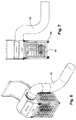
- the Figures 1 and 2 show from different perspectives a filter device 100 for room air filtration for renovation work in buildings.
- the filter device 100 includes a housing 10 in which a dust filter 11 is disposed, as in FIG Fig. 3 is shown.
- the filter 11 is a fine filter, namely a hollow cylindrical HEPA filter.
- the filter is arranged in a box-shaped filter chamber 12 of the housing 11 or is fastened there.
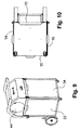
- the filter chamber 12 is delimited by four wall sides 13 to 16, which in the Fig. 10 Marked are.
- the wall side 13 is a closed rear side, whereas the sides 14 to 16 are filter sides.
- the wall sides 14 to 16 of the filter chamber 12 form air inlet sides. These comprise a window-like frame 17, which forms an opening 18.
- Each of the three openings 18 can be covered by a coarse filter 19.
- Fig. 1 shows that the filter 19 has been removed from the side 15 and that the coarse filter is mounted on the side 16.
- the filter 19 comprises a filter holder 20, in which a filter plate 21 is inserted, as the Figures 1 and 2 illustrate.
- the filter holder 20 has a lattice structure, wherein the filter plate 21 lies downstream in the flow direction.
- a housing cover 22 is arranged, which in the FIGS. 3 and 4 is shown exploded.
- the housing cover 22 is removable and / or hinged. That is, the housing cover 22 is designed lid-like, to release the filter chamber 12.
- open state Fig. 3, Fig. 4
- the fine filter 11 can be removed through a filter opening 25 of the housing 10.
- FIG. 3 On the housing cover 22, two air outlet openings 26, 27 are arranged.
- An air outlet opening 26 is eg in Fig. 3 to see while the other air outlet opening 27 eg in Fig. 5 is shown.
- a fan or blower is housed in the area of the housing cover 22 in the area of the housing cover 22, a fan or blower is housed.
- control and / or display elements are mounted to switch eg different fan stages or to realize a level indicator or filter change indicator.
- the device 100 thus comprises a HEPA filter and a fan for dust extraction, wherein the housing is provided with a plurality of air inlet sides or wall sides 14 to 16 and two air outlet openings 26, 27 for blowing out the sucked into the housing 10 by the fan air.
- the fan generates a negative pressure on each air outlet side.
- one or more air inlet sides or wall sides 14 to 16 have a detachable adapter plate 29 or 30 (cf. Fig. 3 . Fig. 5 ) for a suction hose 31 or 32 or a detachable cover plate 33, 34 or 35 fastened (see. Fig. 3 . Fig. 9 . Fig. 13 ), so that at one or more air inlet sides optionally a free air intake at not mounted adapter plate 29, 30 or cover plate 33, 34, 35 (see. Fig. 1 and Fig. 2 ) or suction through a suction hose 31 or 32 with mounted adapter plate 29, 30 is possible.
- Fig. 1 a first mode of operation is shown, in which the filter device with only the filters 19 on all three sides 14, 15, 16 (see. Fig. 10 ) Is provided. There is thus a free air intake at not mounted adapter plate 29, 30 or cover plate 33 - 35 shown.
- Fig. 5 shows a second mode of operation in which two tubes 31, 32 are connected to the housing 10. These suction hoses 31, 32 are led to a workstation, where the dust to be sucked off, eg as a result of grinding work, arises.
- the adapter plates 29, 30 are simply attached via the filters 19.
- the adapter plates 29, 30 are detachable and expediently provided with a handle 36, 37 ( Fig. 3 ). To generate the required negative pressure, it is necessary to cover the third side. This is done with the cover plate eg 30. In Fig. 3 It is shown how the front side is closed with the cover plate 34. Because the adapter plates 29, 30 are above the filter 19, the filter effect of the coarse filter is maintained.
- Each adapter plate 29, 30 consists of a metal plate which lies in or on the frame.
- the sheet metal plate has a e.g. circular opening 40 which carries an adapter ring 41, on which the tube 31, 32 can be inserted.
- the adapter ring 41 may be used together with the tube 31, 32 via a positive and / or non-positive connection, e.g. a screw or bayonet connection to be attached to the housing.
- Corresponding adapter rings can also be used for the openings 26, 27, as Fig. 3 shows.
- Fig. 1 shows, but can not be attached to either side of an adapter plate 29, 30 or a cover plate 33, 34.
- FIGS. 6 and 7 illustrate that at least one air outlet opening 26, 27, a blow-out 42 is connected.
- There are two opposite air outlet openings 26, 27 are present, wherein at each air outlet opening 26, 27, a blow-out 42 is connected. So it can be two Ausblasschläuche 42, 43, as Fig. 8 shows, to be connected.
- blow-out hoses 42, 43 can optionally be present at both air outlet openings 26, 27 blow-out hoses 42, 43 or it may be present only at an air outlet opening a blow-42.
- the filter device is designed as a filter car.
- two transport rollers 45 are fixed by a support member 46.
- two smaller support rollers 48 are provided on the underside of the housing.
- a pivotable transport bracket 47 is attached to the housing, this in eg Fig. 1 collapsed and in Fig. 3 unfolded is shown.
- Each tube 31, 32, 42, 43 may have a diameter of 150-400 mm and a length of 3 to 10 meters.
- the device can be designed for 1000 - 10000 m 3 / h.
- the filter device may also have a deviating from the figures housing shape, for example cylindrical.
- the sides or coarse filters therefore do not have to be flat, but can also be curved, so that the walls 13 - 16 can also be other surfaces.
Landscapes
- Engineering & Computer Science (AREA)
- Chemical & Material Sciences (AREA)
- Combustion & Propulsion (AREA)
- Mechanical Engineering (AREA)
- General Engineering & Computer Science (AREA)
- Filtering Of Dispersed Particles In Gases (AREA)
Claims (9)
- Dispositif à filtre (100) pour la filtration de l'air ambiant, en particulier pour des travaux d'assainissement dans des bâtiments, avec un boîtier (10), dans lequel au moins un filtre à poussières (11), en particulier un filtre HEPA, et au moins un ventilateur pour l'aspiration des poussières sont disposés, dans lequel le boîtier (10) est doté de plusieurs côtés d'entrée d'air ainsi que d'au moins une ouverture de sortie d'air (26, 27) pour l'expulsion de l'air aspiré dans le boîtier (10) par le ventilateur et le ventilateur produit une dépression à chaque côté d'entrée d'air, dans lequel une plaque d'adaptateur amovible (29, 30) pour un tuyau d'aspiration (31, 32) ou une plaque de couverture amovible (33, 34, 35) peut être fixée à plusieurs côtés d'entrée d'air, de telle manière que, au choix, une aspiration libre d'air soit possible à plusieurs côtés d'entrée d'air lorsqu'une plaque d'adaptateur (29, 30) ou une plaque de couverture (33, 34, 35) n'est pas montée ou qu'une aspiration par un tuyau d'aspiration (31, 32) soit possible lorsqu'une plaque d'adaptateur (29, 30) est montée, caractérisé en ce qu'il se trouve au total deux ouvertures de sortie d'air (26, 27) opposées l'une à l'autre sur le boîtier (10).
- Dispositif à filtre selon la revendication 1, caractérisé en ce qu'un tuyau d'expulsion (42) peut être raccordé à au moins une ouverture de sortie d'air (26).
- Dispositif à filtre selon la revendication 1 ou 2, caractérisé en ce qu'un tuyau d'expulsion (42, 43) peut être raccordé à chaque ouverture de sortie d'air (26, 27), de telle manière qu'il se trouve au choix un tuyau d'expulsion (42, 43) à chaque ouverture de sortie d'air (26, 27) ou qu'il ne se trouve un tuyau d'expulsion (42, 43) qu'à une partie des ouvertures de sortie d'air (26, 27), dans lequel la ou les autre(s) ouverture(s) de sortie d'air (26, 27) peut/peuvent être couverte(s) par un élément de fermeture (44) ou plusieurs éléments de fermeture.
- Dispositif à filtre selon l'une quelconque des revendications précédentes, caractérisé en ce qu'un filtre grossier ou préfiltre (19) peut être fixé à chaque côté d'entrée d'air.
- Dispositif à filtre selon l'une quelconque des revendications précédentes, caractérisé en ce qu'il comprend au filtre grossier ou préfiltre (19) une structure de grille et une plaque de filtre (21) située derrière celle-ci dans la direction d'écoulement, dans lequel le filtre à poussières (11) constituant un filtre fin dans le boîtier (10), en particulier le filtre HEPA, est réalisé sous forme cylindrique creuse.
- Dispositif à filtre selon l'une quelconque des revendications précédentes, caractérisé en ce que le boîtier (10) est doté au total de trois côtés d'entrée d'air.
- Dispositif à filtre selon la revendication 6, caractérisé en ce que seule une plaque d'adaptateur (30) au choix avec un tuyau d'aspiration (31) peut être fixée au boîtier (10), tandis que les deux autres côtés d'entrée d'air sont munis de plaques de couverture (33, 34) et en ce que deux des trois côtés d'entrée d'air sur le boîtier (10) peuvent être munis au choix d'une plaque d'adaptateur (29, 30) avec un tuyau d'aspiration (31, 32), tandis que le troisième côté d'entrée d'air est muni d'une plaque de couverture (34), dans lequel cependant une plaque d'adaptateur (29, 30) ou une plaque de couverture (33, 34) ne peut aussi être fixée à aucun côté, de telle manière que les trois côtés puissent tous être choisis comme côtés d'aspiration libres.
- Dispositif à filtre selon l'une quelconque des revendications précédentes, caractérisé par une réalisation sous forme de chariot à filtre.
- Dispositif à filtre selon l'une quelconque des revendications précédentes, caractérisé en ce que le boîtier (10) comprend une chambre de filtre (12) en forme de caisson, dans laquelle un filtre à poussières (11) peut être fixé, dans lequel plusieurs parois latérales (13, 14, 15, 16) de la chambre de filtre (12) forment les côtés d'entrée d'air, et en ce qu'une hotte de boîtier (22) est disposée au-dessus de la chambre de filtre (12), et est réalisée en forme de couvercle afin de libérer la chambre de filtre (12), dans lequel les deux ouvertures de sortie d'air (26) sont disposées dans la hotte de boîtier (22).
Applications Claiming Priority (1)
| Application Number | Priority Date | Filing Date | Title |
|---|---|---|---|
| DE202011050155U DE202011050155U1 (de) | 2011-05-17 | 2011-05-17 | Filtervorrichtung zur Raumluftfilterung, insbesondere für Sanierungsarbeiten in Gebäuden |
Publications (3)
| Publication Number | Publication Date |
|---|---|
| EP2524739A2 EP2524739A2 (fr) | 2012-11-21 |
| EP2524739A3 EP2524739A3 (fr) | 2013-05-08 |
| EP2524739B1 true EP2524739B1 (fr) | 2016-04-06 |
Family
ID=46052604
Family Applications (1)
| Application Number | Title | Priority Date | Filing Date |
|---|---|---|---|
| EP12166329.8A Active EP2524739B1 (fr) | 2011-05-17 | 2012-05-02 | Dispositif à filtre pour la filtration de l'air ambiant, en particulier pour les travaux d'assainissement dans les bâtiments |
Country Status (2)
| Country | Link |
|---|---|
| EP (1) | EP2524739B1 (fr) |
| DE (1) | DE202011050155U1 (fr) |
Families Citing this family (9)
| Publication number | Priority date | Publication date | Assignee | Title |
|---|---|---|---|---|
| WO2017204499A1 (fr) * | 2016-05-23 | 2017-11-30 | 한온시스템 주식회사 | Dispositif de climatisation mobile |
| CN106679009A (zh) * | 2017-03-08 | 2017-05-17 | 嵊州亿源投资管理有限公司 | 一种具有高效率的净化器 |
| AT16330U1 (de) * | 2018-05-23 | 2019-07-15 | Kluge Anton | Filteranordnung |
| NL1043205B1 (nl) * | 2019-03-25 | 2020-10-02 | Demto B V | Afzuiger voor een saneringssysteem |
| DE102019008639B4 (de) * | 2019-12-13 | 2025-03-13 | Trotec Gmbh | Lüfteraufsatz für ein Gerät zur Raumtemperierung oder/und Raumbelüftung sowie entsprechend ausgestattetes Gerät und Temperier- oder/und Belüftungs-System |
| DE202020101309U1 (de) * | 2020-03-10 | 2020-05-07 | TrustFilter UG (haftungsbeschränkt) | Raumluftfilter |
| DE102020001913A1 (de) * | 2020-03-24 | 2021-09-30 | Trotec Gmbh | Strömungsmaschine sowie Steuerung für und Verwendung einer Strömungsmaschine |
| US20240066456A1 (en) * | 2022-05-27 | 2024-02-29 | Mullet Tools, LLC | Air Scrubber |
| EP4425062A1 (fr) | 2023-03-01 | 2024-09-04 | Festool GmbH | Système portable de purification d'air et ensemble d'empilement |
Family Cites Families (5)
| Publication number | Priority date | Publication date | Assignee | Title |
|---|---|---|---|---|
| US3023447A (en) * | 1958-10-15 | 1962-03-06 | Edgar P Senne | Wall-installed vacuum cleaner |
| US4749390A (en) * | 1987-02-26 | 1988-06-07 | Air Purification Products, International | Four-sided air filter |
| US6395047B1 (en) * | 2001-02-16 | 2002-05-28 | William C. Smith | Portable airborne contamination control system including a main and remote unit |
| DE202007014276U1 (de) * | 2007-10-11 | 2008-02-21 | Nexus Ag Plc Limited | Wärmerückgewinnungsaggregat, insbesondere für Zentralstaubsauganlagen und andere Hausgeräte die mit bewegter Luft arbeitet |
| DE102008013383B4 (de) | 2008-03-10 | 2012-02-16 | Edgar Gummerum | Verfahren zur Reinigung mikrobiell kontaminierter Bauten |
-
2011
- 2011-05-17 DE DE202011050155U patent/DE202011050155U1/de not_active Expired - Lifetime
-
2012
- 2012-05-02 EP EP12166329.8A patent/EP2524739B1/fr active Active
Also Published As
| Publication number | Publication date |
|---|---|
| DE202011050155U1 (de) | 2012-08-20 |
| EP2524739A3 (fr) | 2013-05-08 |
| EP2524739A2 (fr) | 2012-11-21 |
Similar Documents
| Publication | Publication Date | Title |
|---|---|---|
| EP2524739B1 (fr) | Dispositif à filtre pour la filtration de l'air ambiant, en particulier pour les travaux d'assainissement dans les bâtiments | |
| DE60304015T2 (de) | Vorrichtung zur Luftreinigung | |
| DE10303730A1 (de) | Staubsauger mit einer ein Scheuertuch enthaltenden Bürste | |
| DE112008001234T5 (de) | Umluft-Staubsauger zum Reinigen von Stoffen und anderen ungespannten Oberflächen | |
| EP2853835A2 (fr) | Dispositif de nettoyage de l'air ambiant | |
| EP0211383A1 (fr) | Filtre | |
| EP1506805A1 (fr) | Dispositif de purification d'air | |
| DE69400122T2 (de) | Filtervorrichtung | |
| DE102005020400A1 (de) | Einrichtung zum Filtern von extrem feinem Staub | |
| DE202016105466U1 (de) | Mehrschichtiges ionisierend entstaubendes kombiniertes Frischluft-Luftreinigungsystem | |
| DE202014010481U1 (de) | Filtervorrichtung | |
| EP3189760A1 (fr) | Machine de nettoyage du sol | |
| DE202020105240U1 (de) | Luftreinigungsvorrichtung zum Filtern von Raumluft | |
| WO2022079069A1 (fr) | Dispositif de nettoyage et utilisation | |
| DE202021100433U1 (de) | Luftfilter-Anordnung zur Reinigung und Desinfektion von Luft | |
| EP2679132B1 (fr) | Aspirateur avec filtre à poussière | |
| DE3719734A1 (de) | Filteraggregat | |
| DE102022107257A1 (de) | Vorrichtung zur Behandlung von Abluft, welche fett- oder ölbelastete Aerosole enthält | |
| EP2496422A1 (fr) | Système d'appareil présentant un appareil de sortie fonctionnant selon le procédé d'impression à particules de fluide d'impression | |
| DE102021204246A1 (de) | Raumluftreinigungsvorrichtung mit Gehäuse-Filter-Einheit | |
| DE102021111081A1 (de) | Vorrichtung zur Luftfilterung | |
| DE60018091T2 (de) | Arbeitsumgebungsraum | |
| AT16620U2 (de) | Vorrichtung zum Reinigen staubbeladener Bauteile | |
| EP4591965A1 (fr) | Filtre à air pour boîtier d'imprimante 3d | |
| DE9400035U1 (de) | Gebläse für ein Kehr- oder Saugfahrzeug |
Legal Events
| Date | Code | Title | Description |
|---|---|---|---|
| PUAI | Public reference made under article 153(3) epc to a published international application that has entered the european phase |
Free format text: ORIGINAL CODE: 0009012 |
|
| AK | Designated contracting states |
Kind code of ref document: A2 Designated state(s): AL AT BE BG CH CY CZ DE DK EE ES FI FR GB GR HR HU IE IS IT LI LT LU LV MC MK MT NL NO PL PT RO RS SE SI SK SM TR |
|
| AX | Request for extension of the european patent |
Extension state: BA ME |
|
| PUAL | Search report despatched |
Free format text: ORIGINAL CODE: 0009013 |
|
| AK | Designated contracting states |
Kind code of ref document: A3 Designated state(s): AL AT BE BG CH CY CZ DE DK EE ES FI FR GB GR HR HU IE IS IT LI LT LU LV MC MK MT NL NO PL PT RO RS SE SI SK SM TR |
|
| AX | Request for extension of the european patent |
Extension state: BA ME |
|
| RIC1 | Information provided on ipc code assigned before grant |
Ipc: B01D 35/30 20060101ALI20130403BHEP Ipc: F24F 7/00 20060101ALI20130403BHEP Ipc: B08B 15/00 20060101AFI20130403BHEP Ipc: F24F 3/16 20060101ALI20130403BHEP |
|
| 17P | Request for examination filed |
Effective date: 20130813 |
|
| RBV | Designated contracting states (corrected) |
Designated state(s): AL AT BE BG CH CY CZ DE DK EE ES FI FR GB GR HR HU IE IS IT LI LT LU LV MC MK MT NL NO PL PT RO RS SE SI SK SM TR |
|
| 17Q | First examination report despatched |
Effective date: 20140929 |
|
| GRAP | Despatch of communication of intention to grant a patent |
Free format text: ORIGINAL CODE: EPIDOSNIGR1 |
|
| INTG | Intention to grant announced |
Effective date: 20151202 |
|
| GRAS | Grant fee paid |
Free format text: ORIGINAL CODE: EPIDOSNIGR3 |
|
| GRAA | (expected) grant |
Free format text: ORIGINAL CODE: 0009210 |
|
| AK | Designated contracting states |
Kind code of ref document: B1 Designated state(s): AL AT BE BG CH CY CZ DE DK EE ES FI FR GB GR HR HU IE IS IT LI LT LU LV MC MK MT NL NO PL PT RO RS SE SI SK SM TR |
|
| REG | Reference to a national code |
Ref country code: GB Ref legal event code: FG4D Free format text: NOT ENGLISH |
|
| REG | Reference to a national code |
Ref country code: AT Ref legal event code: REF Ref document number: 787167 Country of ref document: AT Kind code of ref document: T Effective date: 20160415 Ref country code: CH Ref legal event code: EP |
|
| REG | Reference to a national code |
Ref country code: IE Ref legal event code: FG4D Free format text: LANGUAGE OF EP DOCUMENT: GERMAN |
|
| REG | Reference to a national code |
Ref country code: DE Ref legal event code: R096 Ref document number: 502012006557 Country of ref document: DE |
|
| REG | Reference to a national code |
Ref country code: LT Ref legal event code: MG4D Ref country code: NL Ref legal event code: MP Effective date: 20160406 |
|
| PG25 | Lapsed in a contracting state [announced via postgrant information from national office to epo] |
Ref country code: BE Free format text: LAPSE BECAUSE OF NON-PAYMENT OF DUE FEES Effective date: 20160531 |
|
| PG25 | Lapsed in a contracting state [announced via postgrant information from national office to epo] |
Ref country code: NL Free format text: LAPSE BECAUSE OF FAILURE TO SUBMIT A TRANSLATION OF THE DESCRIPTION OR TO PAY THE FEE WITHIN THE PRESCRIBED TIME-LIMIT Effective date: 20160406 |
|
| PG25 | Lapsed in a contracting state [announced via postgrant information from national office to epo] |
Ref country code: NO Free format text: LAPSE BECAUSE OF FAILURE TO SUBMIT A TRANSLATION OF THE DESCRIPTION OR TO PAY THE FEE WITHIN THE PRESCRIBED TIME-LIMIT Effective date: 20160706 Ref country code: PL Free format text: LAPSE BECAUSE OF FAILURE TO SUBMIT A TRANSLATION OF THE DESCRIPTION OR TO PAY THE FEE WITHIN THE PRESCRIBED TIME-LIMIT Effective date: 20160406 Ref country code: LT Free format text: LAPSE BECAUSE OF FAILURE TO SUBMIT A TRANSLATION OF THE DESCRIPTION OR TO PAY THE FEE WITHIN THE PRESCRIBED TIME-LIMIT Effective date: 20160406 Ref country code: FI Free format text: LAPSE BECAUSE OF FAILURE TO SUBMIT A TRANSLATION OF THE DESCRIPTION OR TO PAY THE FEE WITHIN THE PRESCRIBED TIME-LIMIT Effective date: 20160406 Ref country code: IS Free format text: LAPSE BECAUSE OF FAILURE TO SUBMIT A TRANSLATION OF THE DESCRIPTION OR TO PAY THE FEE WITHIN THE PRESCRIBED TIME-LIMIT Effective date: 20160806 |
|
| PG25 | Lapsed in a contracting state [announced via postgrant information from national office to epo] |
Ref country code: PT Free format text: LAPSE BECAUSE OF FAILURE TO SUBMIT A TRANSLATION OF THE DESCRIPTION OR TO PAY THE FEE WITHIN THE PRESCRIBED TIME-LIMIT Effective date: 20160808 Ref country code: LV Free format text: LAPSE BECAUSE OF FAILURE TO SUBMIT A TRANSLATION OF THE DESCRIPTION OR TO PAY THE FEE WITHIN THE PRESCRIBED TIME-LIMIT Effective date: 20160406 Ref country code: GR Free format text: LAPSE BECAUSE OF FAILURE TO SUBMIT A TRANSLATION OF THE DESCRIPTION OR TO PAY THE FEE WITHIN THE PRESCRIBED TIME-LIMIT Effective date: 20160707 Ref country code: RS Free format text: LAPSE BECAUSE OF FAILURE TO SUBMIT A TRANSLATION OF THE DESCRIPTION OR TO PAY THE FEE WITHIN THE PRESCRIBED TIME-LIMIT Effective date: 20160406 Ref country code: ES Free format text: LAPSE BECAUSE OF FAILURE TO SUBMIT A TRANSLATION OF THE DESCRIPTION OR TO PAY THE FEE WITHIN THE PRESCRIBED TIME-LIMIT Effective date: 20160406 Ref country code: HR Free format text: LAPSE BECAUSE OF FAILURE TO SUBMIT A TRANSLATION OF THE DESCRIPTION OR TO PAY THE FEE WITHIN THE PRESCRIBED TIME-LIMIT Effective date: 20160406 Ref country code: SE Free format text: LAPSE BECAUSE OF FAILURE TO SUBMIT A TRANSLATION OF THE DESCRIPTION OR TO PAY THE FEE WITHIN THE PRESCRIBED TIME-LIMIT Effective date: 20160406 |
|
| PG25 | Lapsed in a contracting state [announced via postgrant information from national office to epo] |
Ref country code: IT Free format text: LAPSE BECAUSE OF FAILURE TO SUBMIT A TRANSLATION OF THE DESCRIPTION OR TO PAY THE FEE WITHIN THE PRESCRIBED TIME-LIMIT Effective date: 20160406 |
|
| REG | Reference to a national code |
Ref country code: DE Ref legal event code: R097 Ref document number: 502012006557 Country of ref document: DE |
|
| PG25 | Lapsed in a contracting state [announced via postgrant information from national office to epo] |
Ref country code: DK Free format text: LAPSE BECAUSE OF FAILURE TO SUBMIT A TRANSLATION OF THE DESCRIPTION OR TO PAY THE FEE WITHIN THE PRESCRIBED TIME-LIMIT Effective date: 20160406 Ref country code: RO Free format text: LAPSE BECAUSE OF FAILURE TO SUBMIT A TRANSLATION OF THE DESCRIPTION OR TO PAY THE FEE WITHIN THE PRESCRIBED TIME-LIMIT Effective date: 20160406 Ref country code: CZ Free format text: LAPSE BECAUSE OF FAILURE TO SUBMIT A TRANSLATION OF THE DESCRIPTION OR TO PAY THE FEE WITHIN THE PRESCRIBED TIME-LIMIT Effective date: 20160406 Ref country code: SK Free format text: LAPSE BECAUSE OF FAILURE TO SUBMIT A TRANSLATION OF THE DESCRIPTION OR TO PAY THE FEE WITHIN THE PRESCRIBED TIME-LIMIT Effective date: 20160406 Ref country code: MC Free format text: LAPSE BECAUSE OF FAILURE TO SUBMIT A TRANSLATION OF THE DESCRIPTION OR TO PAY THE FEE WITHIN THE PRESCRIBED TIME-LIMIT Effective date: 20160406 Ref country code: EE Free format text: LAPSE BECAUSE OF FAILURE TO SUBMIT A TRANSLATION OF THE DESCRIPTION OR TO PAY THE FEE WITHIN THE PRESCRIBED TIME-LIMIT Effective date: 20160406 |
|
| PLBE | No opposition filed within time limit |
Free format text: ORIGINAL CODE: 0009261 |
|
| STAA | Information on the status of an ep patent application or granted ep patent |
Free format text: STATUS: NO OPPOSITION FILED WITHIN TIME LIMIT |
|
| REG | Reference to a national code |
Ref country code: IE Ref legal event code: MM4A |
|
| PG25 | Lapsed in a contracting state [announced via postgrant information from national office to epo] |
Ref country code: SM Free format text: LAPSE BECAUSE OF FAILURE TO SUBMIT A TRANSLATION OF THE DESCRIPTION OR TO PAY THE FEE WITHIN THE PRESCRIBED TIME-LIMIT Effective date: 20160406 |
|
| REG | Reference to a national code |
Ref country code: FR Ref legal event code: ST Effective date: 20170131 |
|
| 26N | No opposition filed |
Effective date: 20170110 |
|
| GBPC | Gb: european patent ceased through non-payment of renewal fee |
Effective date: 20160706 |
|
| PG25 | Lapsed in a contracting state [announced via postgrant information from national office to epo] |
Ref country code: FR Free format text: LAPSE BECAUSE OF NON-PAYMENT OF DUE FEES Effective date: 20160606 |
|
| PG25 | Lapsed in a contracting state [announced via postgrant information from national office to epo] |
Ref country code: SI Free format text: LAPSE BECAUSE OF FAILURE TO SUBMIT A TRANSLATION OF THE DESCRIPTION OR TO PAY THE FEE WITHIN THE PRESCRIBED TIME-LIMIT Effective date: 20160406 Ref country code: IE Free format text: LAPSE BECAUSE OF NON-PAYMENT OF DUE FEES Effective date: 20160502 Ref country code: GB Free format text: LAPSE BECAUSE OF NON-PAYMENT OF DUE FEES Effective date: 20160706 |
|
| PG25 | Lapsed in a contracting state [announced via postgrant information from national office to epo] |
Ref country code: CY Free format text: LAPSE BECAUSE OF FAILURE TO SUBMIT A TRANSLATION OF THE DESCRIPTION OR TO PAY THE FEE WITHIN THE PRESCRIBED TIME-LIMIT Effective date: 20160406 Ref country code: HU Free format text: LAPSE BECAUSE OF FAILURE TO SUBMIT A TRANSLATION OF THE DESCRIPTION OR TO PAY THE FEE WITHIN THE PRESCRIBED TIME-LIMIT; INVALID AB INITIO Effective date: 20120502 |
|
| PG25 | Lapsed in a contracting state [announced via postgrant information from national office to epo] |
Ref country code: MK Free format text: LAPSE BECAUSE OF FAILURE TO SUBMIT A TRANSLATION OF THE DESCRIPTION OR TO PAY THE FEE WITHIN THE PRESCRIBED TIME-LIMIT Effective date: 20160406 Ref country code: LU Free format text: LAPSE BECAUSE OF NON-PAYMENT OF DUE FEES Effective date: 20160502 Ref country code: TR Free format text: LAPSE BECAUSE OF FAILURE TO SUBMIT A TRANSLATION OF THE DESCRIPTION OR TO PAY THE FEE WITHIN THE PRESCRIBED TIME-LIMIT Effective date: 20160406 Ref country code: MT Free format text: LAPSE BECAUSE OF FAILURE TO SUBMIT A TRANSLATION OF THE DESCRIPTION OR TO PAY THE FEE WITHIN THE PRESCRIBED TIME-LIMIT Effective date: 20160406 |
|
| PG25 | Lapsed in a contracting state [announced via postgrant information from national office to epo] |
Ref country code: BG Free format text: LAPSE BECAUSE OF FAILURE TO SUBMIT A TRANSLATION OF THE DESCRIPTION OR TO PAY THE FEE WITHIN THE PRESCRIBED TIME-LIMIT Effective date: 20160406 |
|
| PG25 | Lapsed in a contracting state [announced via postgrant information from national office to epo] |
Ref country code: AL Free format text: LAPSE BECAUSE OF FAILURE TO SUBMIT A TRANSLATION OF THE DESCRIPTION OR TO PAY THE FEE WITHIN THE PRESCRIBED TIME-LIMIT Effective date: 20160406 |
|
| PGFP | Annual fee paid to national office [announced via postgrant information from national office to epo] |
Ref country code: CH Payment date: 20190523 Year of fee payment: 8 |
|
| PGFP | Annual fee paid to national office [announced via postgrant information from national office to epo] |
Ref country code: AT Payment date: 20190517 Year of fee payment: 8 |
|
| REG | Reference to a national code |
Ref country code: AT Ref legal event code: MM01 Ref document number: 787167 Country of ref document: AT Kind code of ref document: T Effective date: 20200502 |
|
| PG25 | Lapsed in a contracting state [announced via postgrant information from national office to epo] |
Ref country code: AT Free format text: LAPSE BECAUSE OF NON-PAYMENT OF DUE FEES Effective date: 20200502 Ref country code: CH Free format text: LAPSE BECAUSE OF NON-PAYMENT OF DUE FEES Effective date: 20200531 Ref country code: LI Free format text: LAPSE BECAUSE OF NON-PAYMENT OF DUE FEES Effective date: 20200531 |
|
| REG | Reference to a national code |
Ref country code: DE Ref legal event code: R082 Ref document number: 502012006557 Country of ref document: DE Ref country code: DE Ref legal event code: R082 Ref document number: 502012006557 Country of ref document: DE Representative=s name: STOLMAR & PARTNER PATENTANWAELTE PARTG MBB, DE |
|
| P01 | Opt-out of the competence of the unified patent court (upc) registered |
Effective date: 20230512 |
|
| REG | Reference to a national code |
Ref country code: DE Ref legal event code: R082 Ref document number: 502012006557 Country of ref document: DE Representative=s name: STOLMAR & PARTNER PATENTANWAELTE PARTG MBB, DE |
|
| REG | Reference to a national code |
Ref country code: DE Ref legal event code: R081 Ref document number: 502012006557 Country of ref document: DE Owner name: DANTHERM GMBH, DE Free format text: FORMER OWNER: HEYLO DRYING SOLUTIONS GMBH, 28832 ACHIM, DE |
|
| PGFP | Annual fee paid to national office [announced via postgrant information from national office to epo] |
Ref country code: DE Payment date: 20250529 Year of fee payment: 14 |