EP2524860B1 - Remorque pliante - Google Patents
Remorque pliante Download PDFInfo
- Publication number
- EP2524860B1 EP2524860B1 EP11004089.6A EP11004089A EP2524860B1 EP 2524860 B1 EP2524860 B1 EP 2524860B1 EP 11004089 A EP11004089 A EP 11004089A EP 2524860 B1 EP2524860 B1 EP 2524860B1
- Authority
- EP
- European Patent Office
- Prior art keywords
- axis
- trailer
- loading platform
- pivoting
- movement
- Prior art date
- Legal status (The legal status is an assumption and is not a legal conclusion. Google has not performed a legal analysis and makes no representation as to the accuracy of the status listed.)
- Not-in-force
Links
Images





Classifications
-
- B—PERFORMING OPERATIONS; TRANSPORTING
- B62—LAND VEHICLES FOR TRAVELLING OTHERWISE THAN ON RAILS
- B62D—MOTOR VEHICLES; TRAILERS
- B62D63/00—Motor vehicles or trailers not otherwise provided for
- B62D63/06—Trailers
- B62D63/061—Foldable, extensible or yielding trailers
-
- B—PERFORMING OPERATIONS; TRANSPORTING
- B60—VEHICLES IN GENERAL
- B60D—VEHICLE CONNECTIONS
- B60D1/00—Traction couplings; Hitches; Draw-gear; Towing devices
- B60D1/14—Draw-gear or towing devices characterised by their type
- B60D1/167—Draw-gear or towing devices characterised by their type consisting of articulated or rigidly assembled bars or tubes forming a V-, Y- or U-shaped draw gear
- B60D1/1675—Draw-gear or towing devices characterised by their type consisting of articulated or rigidly assembled bars or tubes forming a V-, Y- or U-shaped draw gear comprising extendable, retractable or foldable members
Definitions
- the invention relates to a transport trailer for motor vehicles, with a cargo area, Wegholmen and a rubber spring axis, which is collapsible for storage purposes.
- Trailers for passenger cars can be found both in the private and commercial sector. As a uniaxial trailer in the lower weight range, they are usually equipped with an unrestrained axle and have a cargo area. It is available as a low loader with the loading area between the wheels and as a high loader with a loading area above the wheels.
- a rubber spring axle means an axle element including suspension for the right and left wheels as well as suspension and damping.
- This can e.g. besides a rubber spring axis also be a torsion spring axis, but also a system with compression springs or rubber buffers or the axle element consists of individual Laufstummeln. With the axis or rubber spring axis so that is not directly the axis of rotation of the wheels meant.
- the rubber spring axle can be both braked and unbraked.
- the loading surface means any kind of useful upper side.
- This may be a closed area e.g. for motorcycle transport, a general trailer with closed surface and a box structure with side walls, and also an open frame structure with one or more ramps for transporting motorcycles.
- the side walls can be made of aluminum, steel or wood.
- any type of connection forward to the ball coupling which may mean both two or more Buchholme (also called V-drawbar), as well as a central drawbar.
- FR 2883250-B1 and CA 2631836 A1 are based on a folding of the axis about an axis of rotation parallel to the wheel axis. This ends in an approximately 180 degrees rotated orientation of the axis. This folding is made possible by also the drawbar and the axis are rotatably connected to each other, and for folding over the axis erecting the trailer is necessary in advance or it requires considerable effort with eg hydraulic assistance. Furthermore, in the above inventions, the wings must be dismantled in an additional step or they remain in Originalpo position and thus do not contribute to space savings.
- the generic application EP 2246242A1 shows the semicircular pivoting movement, in which the bed front edge slides along the Werholme, while the trailing edge describes approximately a semi-circular motion.
- the generic application DE 3200792 makes the cargo area either linearly or pivotally movable, but has not connected the rubber spring axis rigid with the drawbar, but a joint.
- the generic application NL 1030534 has the cargo bed longitudinally displaceable and tiltable at the rear end.
- the shift is very limited. During the movement, the cargo bed can tilt or lift off. The lock does not catch at the end of the movement automatically.
- Trailers where the axle is displaceable with respect to the chassis can be found e.g. on boat trailers, semi-trailers or in agriculture. This serves primarily to move the axle to match the particular center of gravity, or to adjust the drawbar trailer load. In the case of boat trailers, this is not possible without tools and in agriculture, this is usually achieved by hydraulic assistance.
- the indicated in claim invention is in particular the problem that uniaxial car trailer and sometimes also the above mentioned exist trailer solutions can not be accommodated in addition to a normal car in a common single garage, because there around the car often only less than 40 cm is space and the height does not allow vertical positioning. This problem is solved by the features listed in the claim.
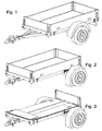
- the advantages achieved by the invention are in particular that the trailer for storage without tools and can be folded flat in less than a minute by a person and thereby moves the cargo area in a favorable position for storage ( Fig 1-5 ).
- the first step for folding is moving the bed forward. This shifts the axis relative to the loading area to eg the rear end, which makes possible the different storage variants.
- This step of moving is feasible in only 2-3 seconds and is made possible by the fact that the shift is clearly guided and that the necessary opening and re-engagement of the lock is done without tools.
- the orientation of the axis does not change during the shift or possibly only minimally. The fact that the axis remains in the displacement on the ground and does not swing in a, for example, 180 degrees rotated orientation, you need not lift the weight of wheels and axle at the loading area.
- the primary goal is the vertical storage on garage or house walls.
- the heavy axis is down ( Fig. 7 ), whereby the erection with an acceptable force by hand by a person is possible.
- the maximum space savings can be achieved by raising the wheels upwards ( Fig. 6 ), which is possible because of the high weight to be moved axle and wheels almost only with 2 people and therefore ideally by means of a pull rope (1) and a manual or electric winch is performed, which are mounted on the garage walls.
- the storage on the front side or the side wall of a garage with the wheels upwards allows virtually the full preservation of space for the car, since the flat-folded and placed on the wall trailer only about 20 cm space required.
- the trailer with 4 ropes and a winch can be pulled flat under the ceiling. It is also conceivable that the trailer is stored in garages lying flat on the ground and a conventional car by means of additional Auffahrbleche can park on or above the trailer.
- FIGS. 8 and 9 Another advantage is the saving of space along the entire value chain from production to sale to the end customer.
- the trailer can be stacked with its peers in its production, storage, delivery and in the sales environment to save space, resulting in transport and storage space savings.
- saving options are becoming increasingly important, especially at the time of delivery.
- FIGS. 8 and 9 the possibility of shifting the axle to the end of the trailer allows Vercardstapelung ( FIGS. 8 and 9 ).
- Fig. 8 a stack of several flat ( Fig. 8 ) lying supporters, with every second on the back and is additionally rotated by 180 degrees about the vertical axis.
- up to 8 stacks of 8 trailers 64 trailers can be transported by truck.
- FIG. 9 shows a similar pallet-like frame with stationary loading.
- the construction described also has the advantage that it is largely made of standard components (eg rubber case, side walls, closures) and that no security-relevant parts have to be dismantled for the folded delivery to the trade.
- steps 2 and 3 are not necessary.
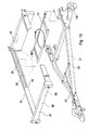
- FIG. 10 and 11 show the variant with a semi-rotational movement by means of a pivoting element, here a swing frame
- FIGS. 12 and 13 show a roller-guided linear displacement.
- the pivotable frame has the advantage that the longitudinal forces occurring during travel, both in the direction of travel and in the opposite direction, are taken over the frame and not on the lock.
- the lock must only prevent lifting the loading area upwards.
- the pivotal frame allows a movement with less effort and less risk that the mechanism canted, or even in light frame deformation at all still works.
- the two end points of the movement are at the same height or offset in height.
- the two end points of the pivoting movement also deliberately be chosen differently high, for example, to ensure the necessary wheel spacing for the suspension in the driving condition, and then in the storage condition as possible close to the loading area from below.
- the trailing edge of the cargo bed describes a semicircle about an axis of rotation parallel to the wheel axis, while the front lower edge slides linearly along the tow bars or even rolls along it.
- the wheel axle When driving, the wheel axle is slightly positioned (e.g., 60mm) behind the bed center and locked. However, it is interesting for the incorporation that the axis lies clearly outside the center, e.g. as shown at the back end.
- the movement of the cargo bed is achieved via a pivoting element.
- This pivoting element may consist of one or more levers or struts, it may be a U-shaped frame, or be a completely closed frame.
- each locking pin is activated by a lateral pin (35) by a respective slot (32) from the outside. This is done by a Bowden cable (37) and a hand lever (38).
- the hand lever is positioned in the area above the license plate or above a rear reflector of the rear underrun protection panel.
- This sheet has a cutout ( FIG. 10 ) (28) to allow for greater leeway for the lever.
- the cut-out can additionally be equipped with a recessed grip to protect the lever against splashing dirt.
- the swing frame is rotatably attached (25) to the cargo bed side profile (24) with the openings (30).
- the protruding ends (36) of the locking pin (33) engage in the 2 possible positions in the locking holes (26).
- the sloping bottom edge (29) of the loading side profile also allows automatic engagement, without having pulled the operating handle (38).
- the tube (31) of the swing frame which also includes the Arretierstäbe is also the same axis for receiving a respective torsion spring (39) right and left.
- These springs serve to facilitate the lifting of the cargo area from the respective end positions.
- the springs are maximally relaxed when the frame is approximately vertically upwards at the apex, and they have the largest restoring moments when the frame is swiveled about 90 degrees forward and also 90 degrees backwards.
- the load-compensating springs can also be designed as tension springs below the swing frame, or as a torsion Stabfedem. Both the axes of rotation of the pivoting frame and the lock do not necessarily have to be centrally integrated in the individual frame profiles at the same time, but may also be positioned outside the transverse profiles.
- the rubber spring axle (41) special support blocks (42) on which upper (43) and lower (44) rollers are attached.
- the loading area (46) is bordered by a lateral edge profile (45) which has pronounced guides (47) for the upper and lower rollers.
- This profile with the function of a running rail can be both an aluminum extruded part, a separately screwed rail element, or be folded in the example shown from the sheet steel edge profile. End stops are achieved by cross-threading through these frame profiles.
- a secure locking is achieved by locking bolts similar to the pivot frame, wherein the locking pins engage in holes in the inner region of the edge profile (49).
- the rear cross tube ( Fig. 17 ) (50) for supporting the rear Eckrungen (52) also simultaneously as a handle for both hands to move the cargo area.
- the lever (38) for the swing frame locking is positioned from the operator's view directly behind the cross tube (50) (in the direction of travel in front of the cross tube) above the license plate, so that you can simultaneously solve the lock and lift the bed, similar to the lever one Bicycle brake on the handlebar.
- the lock must not be bolt-shaped, for example. Any types of positive connection are conceivable.
- the lock does not necessarily have to be triggered by a Bowden cable. Important is a remote control so that on both sides of the cargo bed and the axle can lock together, and this can be conveniently operated by a person behind the trailer.
- the Bowden cable offers the advantage of its flexibility, because the distance between locking point and lever in the different end points is different. Push, pull or rotary linkage are also conceivable.
- each page has its own lever or at least 2 separate, but emanating from a common lever remote controls.
- the upper points of the fenders are generally higher than the loading area and even higher than the loading area, including the side walls folded flat on them.
- the fenders are indeed suspended pivotally that they have the necessary distance to the tire for the immersion of the suspension in the driving condition ( FIG. 14 ) (130), but in the stowed state this distance is minimized (131).
- the fenders with the loading area do not move forward when the loading area is moved forwards, but in principle remain behind together with the wheels. But they are doing a move closer to the Tires come up. For such a transfer to a new position there are possibilities of complete dismantling, or there are guided movements. In the guided movements pivotal movements, linear movements or Paralleogrammterrorismen are conceivable.
- the embodiment has several advantages in particular by the choice of a pivoting movement and by the particular choice of the pivot point with a rotation axis parallel to the wheel axle.
- the vertical distance to the tire is reduced.
- the fender can be so consciously keep a few mm distance to the tire, so that the folded trailer can still be maneuvered without the fender grind on the tire.
- the choice of the fulcrum behind the wheel axle has the advantage that, with an approximately 45 degrees rotation of the fender, this also moves forward overall.
- the pivoting nature of the mudguard movement is very easily achieved by means of an active element, i. e.g. Tension element (such as a spring, an elastic band or linkage) or with a gear or chain connection to the bed displacement couple.
- an active element i. e.g. Tension element (such as a spring, an elastic band or linkage) or with a gear or chain connection to the bed displacement couple.
- the position of the fender pivot axis (76) is deliberately about 133 mm behind and 21 mm above the wheel axle (132) selected, suitable for common 145/80 R13 tires, so that the fenders in the driving position the necessary vertical distance (130) (eg 120 mm) to the wheels for immersing the suspension and also on the same side allow the ideal storage position.
- this means that the fender pivot point is about 25% of the tire outer diameter behind the wheel axle, and about 4% more.
- An active element such as in this case a tension spring (77) attached to the lateral loading surface profile (78) pulls the fender in the driving position to the rear, so that the stop (79) abuts against the support plate (73) of the support blocks (72).
- the mudguard makes an approx. 45 degree (80) rotary movement until the recess (81) acts as a stop against the leg (82) of the rubber spring axis (70) abuts. In this position, the fender (75) with a minimum distance (131) directly above the wheels to save space for storage, but still be able to move the trailer by means of wheels.
- the stops can ideally be limited by height adjustable elements such as Einschraubgummipuffem, which are also known, for example, in car hoods.
- each fender is made up of several segments, and these mutually move, e.g. two halves that move closer to each other, or 2 circle-segment parts that overlap more or less by an arcuate motion.
- the tailgate (53) is not struck (56) on a fixed part of the box body but on the rear cross tube (50). Therefore, it is not necessary to open the closures (54) of the tailgate (shown here visibly as the back of a long-travel closure), but instead the rear closures of the lateral side walls, which engage from the front (55) in the Eckrept. Thereby, the rear corner stanchions (52) can be released from the lateral side walls and folded down as a part together with the tailgate (53) around the pivot point (51).
- the closures (91) are shown as long-travel closure, wherein a fixed positioning pin (93) and a moving cap bolt (92) projecting in the direction of travel to the rear and engage in the matching openings (94) of the end faces of the end profile of the lateral side walls.
- a hinge for example, piano bands can be used or hinges which are formed directly from the extruded aluminum profile of the lateral side walls, milled as a rotatable backdrop or segmentally like a piano strap and with inserted rotary axis.
- film hinges using rubber, fabric, polyurethane or other flexible material are possible, which are attached to the bottom of the side wall profile.
- various types of attachment such as a piping, a terminal strip or a permanent polyurethane-aluminum compound as in the product "Poliall” from Pastore and Lombardi in use for truck rear doors.
- 3 hinge elements were used as a hinge for the lateral side walls per longitudinal side.
- a vertical eyebolt (98) is inserted through a short vertical guide tube (97).
- the upper hinge element (100) is screwed from below to the side wall (95) and engages in the eyebolt (98).
- the side wall (95) must first be raised by approx. 40 mm, which is achieved by pulling the eye bolt (98) in the short tube (97) approx. 40 mm up to the end stop (99) becomes. Then it can be folded inwards.
- This variant has 2 particular advantages: It can also be easily removed after removing the end stop (99), for example, for the transport of motorcycles, and they are not so sensitive to damage, if still lying Ladegutreste near the axis of rotation when folding. Furthermore, these hinges are insensitive to contamination and easy to replace as a spare part. Both the hinge parts, as well as the side walls are standard elements of trailer construction.
- the last side wall is folded inwards.
- the embodiment shows a bolt ( Fig. 15 ) (101) as an axis of rotation, which protrude into the lower region of the long-lever lock (91).
- the closures (91) of the front side wall are designed so that they firmly connect both the lateral and front side wall in the driving position, as well as fix flat in the flat position, the front side wall. The latter is intended to ensure that in the state of vertical storage (especially when the trailer front or the top down shows) all inwardly folded side walls are secured against unintentional opening.
- the embodiment shows how the cap bolt (92) (or screw with a large head) behind a plate (96) engages, which is fixed from below to the lateral side wall (95). With the flattening of the lateral side wall, the plate (96) rotates in the horizontal and represents with the outer contour half of the keyhole-shaped contour as (94).
- the rear flap does not fold down to the outside, but also on the inside of the truck bed.
- front corner stanchions As an alternative to connecting front and side sidewalls directly to a closure, it is also possible to use front corner stanchions. This is especially interesting because you can use the trailer with folded down front side wall to transport long load or a motorcycle. For this "load through” the stability with respect to lateral forces on the side walls is then achieved by the rear and front corner stanchions.
- the additional front corner stanchions can be made completely removable as well as the rear corner stanchions fold away.
- folding mechanisms are possible in which one or more stanchions are firmly connected to the ship's side walls. To fold this whole unit is first raised and then folded inwards.
- lifting the stakes are pulled out of their Einsteckprofil vertically a piece and then folded, as for example. is common for reusable steel pallets with retractable attachment frame.
- This folding movement is in the embodiment ( Fig. 18-21 ) solved in that after loosening the lock (6) the ball coupling (119) with the drawbar stub (4) initially about 90 degrees down from the guide element, in this case, the U-shaped guide (5) folds out. Then it is folded about 90 degrees to one side and fixed in a final movement by means of the coupling closure on a ball or a ring (113) or a disc.
- the use of a ring or disc is used to reduce weight, since the clutch does not have to withstand driving forces in this state. Throughout the movement of the clutch handle matches the operator, which only has to raise the trailer front side for this Einklappvorgang or temporarily alsetcm.
- the guide element may be a U-shaped profile (5), which is screwed (9) between the two Switzerlandholmen.
- the U can also be easily formed from the drawbar profile itself.
- the U-profile and the appropriate drawbar stub (4) ideally have oblique lateral flanks, or partially oblique flanks ( Fig. 22 ) (118) or oblique ribs. These serve for easier insertion of the drawbar stub and the vibration-free clamping.
- a cardan-like joint Fig. 20
- a transverse wall (105) in the U-profile Approximately on the central longitudinal axis in the U-profile of the foldable drawbar stub by means of a cardan-like joint ( Fig. 20 ) (105-109) connected to a transverse wall (105) in the U-profile.
- This joint allows both the folding down as well as the lateral turning away.
- the rotational movement of the universal joint is carried out by means of an eye bolt (107), which can rotate in the welded threaded bushing (106).
- Other rotary joints without a thread are of course also possible.
- the eyebolt is connected by a bolt (109) rotatably connected to the fork opening (108), which is an integral part of the drawbar hump (4).
- the one-sided recess (111) directly behind the fork opening and the one-sided recesses (110) in both the U-profile (5) and in the overlying Switzerlandholm allow pivoting to the side.
- the lock ( Fig. 22 ) is effected by means of a spring-loaded (117) bolt (116), which is guided in a tube (115) and engages in a bore (7) in the lateral U-profile wall.
- the wall profile is slightly inclined below (8) to ensure automatic locking.
- the drawbar stub and U-profile are clamped together.
- This is a clamping lever screw (6) which ends in the bolt (116) with a thread (114) and can be folded forward by rotation of the bolt in the direction of travel.
- In the U-profile (5) is a forwardly open recess (112) in which the clamping lever pivots.
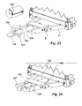
- a second execution example for the removal of the drawbar stub with the ball coupling is retracting.
- the drawbar stub instead of a lateral folding away the drawbar stub is moved linearly under the bed after first a lock is released and the drawbar stub is gredeht by 90 degrees.
- Fig. 23 (128) shows this movement.
- This method has the advantage that it is easier to manufacture and is composed of closed and thus stable round profiles and thus makes less weight.
- the Switzerlandholme (21) are mounted with large lateral distance from each other ( FIGS. 23 and 24 ) and are connected to a cross-beam (122) similar to the overrun brakes braked trailers.
- the ball coupling (119) has by its handle (120) and the pole base (121) a certain height.
- a pallet-like frame ( FIGS. 8 and 9 ), eg as a disposable wooden frame (60), or as a reusable steel frame.
- Lower cross members have 2 receptacles (61) for forklift forks. This allows, for example, 8 trailers flat on top of each other ( Fig. 8 ) in a frame, eg with screws (62), which engage in the lashing eyes of the trailer. Ideally, such a frame would be strained with diagonal ropes (63) or straps.
- the frame allows handling with forklifts, storage in a racking system or the block stacking of several racks on top of each other without shelving system.
- a similar patette-like frame with standing pendants ( FIG. 9 ) has the additional advantage that it can be placed as a full frame, for example in the outdoor area of a hardware store and the trailer can be loaded and unloaded from this frame with eg only 2 people without the aid of forklifts.
Landscapes
- Engineering & Computer Science (AREA)
- Transportation (AREA)
- Mechanical Engineering (AREA)
- Chemical & Material Sciences (AREA)
- Combustion & Propulsion (AREA)
- Body Structure For Vehicles (AREA)
Claims (15)
- Remorque de transport pour un véhicule automobile comportant une zone de chargement (46), comportant un essieu à ressort en caoutchouc (70) et comportant un guidage (20 ou 47), avec lequel la zone de chargement est mobile par rapport à l'essieu à ressort en caoutchouc pour passer d'une position de roulage vers l'avant à une position de stockage, l'essieu à ressort en caoutchouc présentant, dans la position de roulage et dans la position de stockage, la même orientation par rapport à la zone de chargement, et la zone de chargement étant mobile manuellement et sans l'aide d'outils au moyen d'un guidage (20 ou 47),
caractérisée en ce que la remorque de transport présente des garde-boue (75) avec des guidages (76) qui guident les garde-boue sans outils alternativement entre une position de roulage, dans laquelle ils sont à distance (130) des roues de la remorque de transport, et une position de stockage, dans laquelle ils sont rabaissés (131) verticalement en se rapprochant des roues. - Remorque de transport selon la revendication 1,
caractérisée en ce que le mouvement guidé des garde-boue (75) s'effectue en se rapprochant des roues par un mouvement de pivotement autour d'un axe (76), qui est orienté de manière parallèle à l'axe de rotation de roue (132) et est préférentiellement positionné à environ un demi-rayon extérieur de roue derrière l'essieu. - Remorque de transport selon la revendication 1 ou 2,
caractérisée en ce que le mouvement guidé des garde-boue (75) s'effectue automatiquement par le mouvement de la surface de chargement (46) au moyen d'un élément actionneur (77). - Remorque de transport selon la revendication 1,
caractérisée en ce que le mouvement de la surface de chargement par rapport à l'essieu à ressort en caoutchouc est guidé par une liaison sous la forme d'un élément de pivotement (20), qui pivote autour d'un premier axe (27) de manière parallèle à l'essieu (132) et avec lequel la surface de chargement est reliée de manière pivotante autour d'un second axe (25/30), qui est disposé parallèle à et à distance du premier axe. - Remorque de transport selon les revendications 1 et 4,
caractérisée en ce que l'élément de pivotement (20) présente au moins un élément d'assistance élastique (39) qui, lors du mouvement de pivotement à 180 degrés, tend l'élément de pivotement autant à partir de la direction 0 degré que de la direction 180 degrés respectivement dans la position centrale à 90 degrés (respectivement approximativement). - Remorque de transport selon la revendication 1,
caractérisée en ce que le mouvement de la surface de chargement par rapport à l'essieu à ressort est principalement linéaire et est assisté par des galets (43/44) ou des guidages de garde-boue. - Remorque de transport selon les revendications 1, 4, 5, 6,
caractérisée en ce que la liaison de la zone de chargement à l'essieu présente au moins un élément d'arrêt (36), qui est actionné au moyen d'un dispositif de commande à distance mécanique (32, 37, 38). - Remorque de transport selon les revendications 1, 4, 5, 6, 7,
caractérisée en ce que cet élément d'arrêt (36) fixe la surface de chargement autant dans la position de roulage (Fig 1) que dans la position de stockage (Fig 5). - Remorque de transport selon les revendications 1, 4, 6,
caractérisée en ce que le déplacement de la surface de chargement dans la position de roulage se termine automatiquement par au moins une liaison par complémentarité de forme (22) entre la zone du chant avant de la surface de chargement et les longerons (21) ou par un entrecroisement entre ces longerons. - Remorque de transport selon la revendication 1,
caractérisée en ce que, dans le cas de la version de surface de chargement avec caisse, au moins les ranchers arrière (52) sont repliables vers le bas par un mouvement de pivotement. - Remorque de transport selon la revendication 10,
caractérisée en ce que les ranchers droit et gauche (52), respectivement à la même hauteur par rapport à la direction de roulage, sont reliés solidairement entre eux dans la zone inférieure (50) et peuvent être abaissés conjointement par un mouvement di pivotement en formant une unité. - Remorque de transport selon les revendications 1, 4, 6,
caractérisée en ce que, après le déplacement de la surface de chargement dans la position de stockage, la majeure partie du timon (21) alors encore en saillie sous la surface de chargement est positionnée comme un tronçon de timon (4) conjointement avec l'accouplement de boule d'attelage (119) dans un élément de guidage (5) et est rabattable ou repliable après le déclenchement d'un élément d'arrêt (6). - Remorque de transport selon les revendications 1, 4, 6, 12,
caractérisée en ce que, lors du repliement du tronçon de timon (4), ce dernier décrit un mouvement qui se compose principalement d'au moins 2 segments en arc : a) environ 90 degrés vers le bas hors de l'élément de guidage autour d'un axe de manière parallèle à l'essieu, puis b) environ 90 degrés vers un côté reposant à plat sous la surface de chargement au moyen d'une rotation autour inviron d'un axe orienté dans la direction de roulage. - Remorque de transport selon les revendications 1, 4, 6, 12,
caractérisée en ce que, lors de l'escamotage du tronçon de timon, ce dernier décrit un mouvement qui se compose principalement d'au moins 2 segments : a) entraînement en rotation d'environ 90 degrés autour de l'axe longitudinal du tronçon de timon, puis b) déplacement linéaire dans la direction de roulage vers l'arrière. - Remorque de transport selon l'une des revendications 1 à 14,
caractérisée en ce qu'un entreposage et une livraison de plusieurs remorques s'effectuent dans une position de stockage respectivement pliée, formée soit d'une pile de remorques superposées les unes sur les autres, soit d'une série de remorques debout les unes derrière les autres, la face supérieure de chargement étant orientée dans la direction opposée pour une remorque sur deux et des paires étant formées par 2 remorques, l'une étant positionnée tournée à 180 degrés par rapport à l'autre autour d'un axe de manière parallèle à l'essieu (132).
Priority Applications (1)
| Application Number | Priority Date | Filing Date | Title |
|---|---|---|---|
| EP11004089.6A EP2524860B1 (fr) | 2011-05-18 | 2011-05-18 | Remorque pliante |
Applications Claiming Priority (1)
| Application Number | Priority Date | Filing Date | Title |
|---|---|---|---|
| EP11004089.6A EP2524860B1 (fr) | 2011-05-18 | 2011-05-18 | Remorque pliante |
Publications (2)
| Publication Number | Publication Date |
|---|---|
| EP2524860A1 EP2524860A1 (fr) | 2012-11-21 |
| EP2524860B1 true EP2524860B1 (fr) | 2014-06-11 |
Family
ID=44653616
Family Applications (1)
| Application Number | Title | Priority Date | Filing Date |
|---|---|---|---|
| EP11004089.6A Not-in-force EP2524860B1 (fr) | 2011-05-18 | 2011-05-18 | Remorque pliante |
Country Status (1)
| Country | Link |
|---|---|
| EP (1) | EP2524860B1 (fr) |
Cited By (4)
| Publication number | Priority date | Publication date | Assignee | Title |
|---|---|---|---|---|
| RU173665U1 (ru) * | 2017-02-15 | 2017-09-05 | Дмитрий Игоревич Моисеев | Прицеп |
| WO2018151624A1 (fr) * | 2017-02-15 | 2018-08-23 | Дмитрий Игоревич МОИСЕЕВ | Remorque |
| US20240001723A1 (en) * | 2020-12-18 | 2024-01-04 | Systematics Limited | An Adjustable Drawbar |
| IT202300022749A1 (it) * | 2023-10-30 | 2025-04-30 | Cbs S R L | Apparato a timone retrattile per rimorchio di autocarro e relativo rimorchio |
Families Citing this family (7)
| Publication number | Priority date | Publication date | Assignee | Title |
|---|---|---|---|---|
| DE202014000617U1 (de) | 2014-01-22 | 2014-02-14 | Stefan Wenner | Klappbarer Anhänger |
| FR3094921B1 (fr) * | 2019-04-09 | 2021-09-10 | Acea Holding | Dispositif d’attelage d’une remorque pivotant longitudinalement |
| DE102019219461A1 (de) * | 2019-12-12 | 2021-06-17 | Volkswagen Aktiengesellschaft | Anhänger |
| CN111591380B (zh) * | 2020-06-23 | 2025-04-08 | 武汉易知鸟科技有限公司 | 一种救援电动车 |
| FR3112993B1 (fr) * | 2020-07-28 | 2022-08-12 | Wettoncraft | Timon rétractable |
| NL2033478B1 (nl) * | 2022-11-08 | 2024-05-24 | Gehold B V | Aanhanger en combinatie van een trekkend voertuig en een aanhanger |
| DE202023001513U1 (de) | 2023-07-18 | 2023-08-31 | Stefan Wenner | Kotflügelaufhängung für einen absenkbaren Anhänger |
Citations (1)
| Publication number | Priority date | Publication date | Assignee | Title |
|---|---|---|---|---|
| DE3200792A1 (de) * | 1980-11-28 | 1983-07-21 | William Papatoetoe Auckland Hyde | "fahrzeug-anhaenger" |
Family Cites Families (5)
| Publication number | Priority date | Publication date | Assignee | Title |
|---|---|---|---|---|
| FR2883250B1 (fr) | 2005-03-16 | 2007-05-25 | Jean Luc Brosset | Remorque attelable ayant un encombrement minimal en epaisseur en position de rangement |
| NL1030534C2 (nl) * | 2005-11-28 | 2007-06-01 | Andre Van Der Steen | Inrichting voor het transporteren van lading. |
| US20070126209A1 (en) * | 2005-12-05 | 2007-06-07 | Wolfe Arnold R | Convertible trailer |
| GB2466285B (en) | 2008-12-19 | 2012-08-08 | Gordon Allin | Folding trailer |
| EP2246242B1 (fr) * | 2009-04-29 | 2012-11-07 | Sorelpol SP z.o.o. | Remorque pour véhicule automobile comportant une caisse escamotable |
-
2011
- 2011-05-18 EP EP11004089.6A patent/EP2524860B1/fr not_active Not-in-force
Patent Citations (1)
| Publication number | Priority date | Publication date | Assignee | Title |
|---|---|---|---|---|
| DE3200792A1 (de) * | 1980-11-28 | 1983-07-21 | William Papatoetoe Auckland Hyde | "fahrzeug-anhaenger" |
Cited By (6)
| Publication number | Priority date | Publication date | Assignee | Title |
|---|---|---|---|---|
| RU173665U1 (ru) * | 2017-02-15 | 2017-09-05 | Дмитрий Игоревич Моисеев | Прицеп |
| WO2018151624A1 (fr) * | 2017-02-15 | 2018-08-23 | Дмитрий Игоревич МОИСЕЕВ | Remorque |
| US20240001723A1 (en) * | 2020-12-18 | 2024-01-04 | Systematics Limited | An Adjustable Drawbar |
| EP4263249A4 (fr) * | 2020-12-18 | 2024-11-06 | Systematics Limited | Barre de remorquage réglable |
| IT202300022749A1 (it) * | 2023-10-30 | 2025-04-30 | Cbs S R L | Apparato a timone retrattile per rimorchio di autocarro e relativo rimorchio |
| EP4549176A1 (fr) * | 2023-10-30 | 2025-05-07 | CBS S.r.l. | Dispositif de timon escamotable pour remorques de camion et remorques apparentées |
Also Published As
| Publication number | Publication date |
|---|---|
| EP2524860A1 (fr) | 2012-11-21 |
Similar Documents
| Publication | Publication Date | Title |
|---|---|---|
| EP2524860A1 (fr) | Remorque pliante | |
| DE2540395A1 (de) | Ladevorrichtung zum be- und entladen des frachtraumes eines fahrzeuges | |
| DE3200792A1 (de) | "fahrzeug-anhaenger" | |
| DE69101901T2 (de) | Behälter. | |
| DE4335456C2 (de) | Lastkraftwagen für den Transport von Gütern | |
| EP3141455B1 (fr) | Dispositif de transport de marchandises au detail | |
| EP3173286B1 (fr) | Véhicule de transport pour matériaux en vrac | |
| DE102004018910A1 (de) | Flurfolgefahrzeug | |
| DE1630774B2 (de) | Fahrzeug zum transport insbesondere von schweren etwa der fahrzeugbreite entsprechenden lasten | |
| EP1686047B1 (fr) | Remorque pliante | |
| WO2013087125A1 (fr) | Porte-charge | |
| WO2009030486A1 (fr) | Véhicule comprenant une rampe télescopique | |
| AT501357B1 (de) | Behälter | |
| EP1463659B1 (fr) | Chariot | |
| DE4237410C2 (de) | Pritschenaufbau für LKW-Wechselbehälter und Festaufbauten | |
| DE3319107A1 (de) | Lasttrage- und hebevorrichtung an pkw | |
| EP3280615B1 (fr) | Système de réception d'objets | |
| DE102009017925A1 (de) | Fahrradanhänger mit verlängerbarer Ladefläche | |
| DE2319652A1 (de) | Einrichtung zum be- und entladen eines containers bei einem sattelanhaenger | |
| DE202016000285U1 (de) | Einfahrbare Zugholme (Deichsel) für einen Anhänger | |
| DE20307880U1 (de) | Vorrichtung zum Anheben von Lasten im Kofferraum von Kraftfahrzeugen | |
| DE202009005772U1 (de) | Fahrradanhänger mit verlängerbarer Ladefläche | |
| DE9303905U1 (de) | Lastenanhänger | |
| EP3326861A1 (fr) | Dispositif d'arrimage de chargement | |
| DE19950553C2 (de) | LKW-Hubvorrichtung für unterfahrbare Wechselbehälter |
Legal Events
| Date | Code | Title | Description |
|---|---|---|---|
| PUAI | Public reference made under article 153(3) epc to a published international application that has entered the european phase |
Free format text: ORIGINAL CODE: 0009012 |
|
| AK | Designated contracting states |
Kind code of ref document: A1 Designated state(s): AL AT BE BG CH CY CZ DE DK EE ES FI FR GB GR HR HU IE IS IT LI LT LU LV MC MK MT NL NO PL PT RO RS SE SI SK SM TR |
|
| AX | Request for extension of the european patent |
Extension state: BA ME |
|
| 17P | Request for examination filed |
Effective date: 20130408 |
|
| 17Q | First examination report despatched |
Effective date: 20130626 |
|
| GRAP | Despatch of communication of intention to grant a patent |
Free format text: ORIGINAL CODE: EPIDOSNIGR1 |
|
| INTG | Intention to grant announced |
Effective date: 20140103 |
|
| GRAS | Grant fee paid |
Free format text: ORIGINAL CODE: EPIDOSNIGR3 |
|
| GRAA | (expected) grant |
Free format text: ORIGINAL CODE: 0009210 |
|
| AK | Designated contracting states |
Kind code of ref document: B1 Designated state(s): AL AT BE BG CH CY CZ DE DK EE ES FI FR GB GR HR HU IE IS IT LI LT LU LV MC MK MT NL NO PL PT RO RS SE SI SK SM TR |
|
| REG | Reference to a national code |
Ref country code: GB Ref legal event code: FG4D Free format text: NOT ENGLISH |
|
| REG | Reference to a national code |
Ref country code: CH Ref legal event code: EP |
|
| REG | Reference to a national code |
Ref country code: IE Ref legal event code: FG4D Free format text: LANGUAGE OF EP DOCUMENT: GERMAN |
|
| REG | Reference to a national code |
Ref country code: AT Ref legal event code: REF Ref document number: 672108 Country of ref document: AT Kind code of ref document: T Effective date: 20140715 |
|
| REG | Reference to a national code |
Ref country code: DE Ref legal event code: R096 Ref document number: 502011003337 Country of ref document: DE Effective date: 20140724 |
|
| PG25 | Lapsed in a contracting state [announced via postgrant information from national office to epo] |
Ref country code: GR Free format text: LAPSE BECAUSE OF FAILURE TO SUBMIT A TRANSLATION OF THE DESCRIPTION OR TO PAY THE FEE WITHIN THE PRESCRIBED TIME-LIMIT Effective date: 20140912 Ref country code: FI Free format text: LAPSE BECAUSE OF FAILURE TO SUBMIT A TRANSLATION OF THE DESCRIPTION OR TO PAY THE FEE WITHIN THE PRESCRIBED TIME-LIMIT Effective date: 20140611 Ref country code: LT Free format text: LAPSE BECAUSE OF FAILURE TO SUBMIT A TRANSLATION OF THE DESCRIPTION OR TO PAY THE FEE WITHIN THE PRESCRIBED TIME-LIMIT Effective date: 20140611 Ref country code: NO Free format text: LAPSE BECAUSE OF FAILURE TO SUBMIT A TRANSLATION OF THE DESCRIPTION OR TO PAY THE FEE WITHIN THE PRESCRIBED TIME-LIMIT Effective date: 20140911 |
|
| REG | Reference to a national code |
Ref country code: NL Ref legal event code: VDEP Effective date: 20140611 |
|
| REG | Reference to a national code |
Ref country code: LT Ref legal event code: MG4D |
|
| PG25 | Lapsed in a contracting state [announced via postgrant information from national office to epo] |
Ref country code: LV Free format text: LAPSE BECAUSE OF FAILURE TO SUBMIT A TRANSLATION OF THE DESCRIPTION OR TO PAY THE FEE WITHIN THE PRESCRIBED TIME-LIMIT Effective date: 20140611 Ref country code: SE Free format text: LAPSE BECAUSE OF FAILURE TO SUBMIT A TRANSLATION OF THE DESCRIPTION OR TO PAY THE FEE WITHIN THE PRESCRIBED TIME-LIMIT Effective date: 20140611 Ref country code: RS Free format text: LAPSE BECAUSE OF FAILURE TO SUBMIT A TRANSLATION OF THE DESCRIPTION OR TO PAY THE FEE WITHIN THE PRESCRIBED TIME-LIMIT Effective date: 20140611 Ref country code: HR Free format text: LAPSE BECAUSE OF FAILURE TO SUBMIT A TRANSLATION OF THE DESCRIPTION OR TO PAY THE FEE WITHIN THE PRESCRIBED TIME-LIMIT Effective date: 20140611 |
|
| PG25 | Lapsed in a contracting state [announced via postgrant information from national office to epo] |
Ref country code: CZ Free format text: LAPSE BECAUSE OF FAILURE TO SUBMIT A TRANSLATION OF THE DESCRIPTION OR TO PAY THE FEE WITHIN THE PRESCRIBED TIME-LIMIT Effective date: 20140611 Ref country code: SK Free format text: LAPSE BECAUSE OF FAILURE TO SUBMIT A TRANSLATION OF THE DESCRIPTION OR TO PAY THE FEE WITHIN THE PRESCRIBED TIME-LIMIT Effective date: 20140611 Ref country code: RO Free format text: LAPSE BECAUSE OF FAILURE TO SUBMIT A TRANSLATION OF THE DESCRIPTION OR TO PAY THE FEE WITHIN THE PRESCRIBED TIME-LIMIT Effective date: 20140611 Ref country code: EE Free format text: LAPSE BECAUSE OF FAILURE TO SUBMIT A TRANSLATION OF THE DESCRIPTION OR TO PAY THE FEE WITHIN THE PRESCRIBED TIME-LIMIT Effective date: 20140611 Ref country code: PT Free format text: LAPSE BECAUSE OF FAILURE TO SUBMIT A TRANSLATION OF THE DESCRIPTION OR TO PAY THE FEE WITHIN THE PRESCRIBED TIME-LIMIT Effective date: 20141013 Ref country code: ES Free format text: LAPSE BECAUSE OF FAILURE TO SUBMIT A TRANSLATION OF THE DESCRIPTION OR TO PAY THE FEE WITHIN THE PRESCRIBED TIME-LIMIT Effective date: 20140611 |
|
| PG25 | Lapsed in a contracting state [announced via postgrant information from national office to epo] |
Ref country code: PL Free format text: LAPSE BECAUSE OF FAILURE TO SUBMIT A TRANSLATION OF THE DESCRIPTION OR TO PAY THE FEE WITHIN THE PRESCRIBED TIME-LIMIT Effective date: 20140611 Ref country code: NL Free format text: LAPSE BECAUSE OF FAILURE TO SUBMIT A TRANSLATION OF THE DESCRIPTION OR TO PAY THE FEE WITHIN THE PRESCRIBED TIME-LIMIT Effective date: 20140611 Ref country code: IS Free format text: LAPSE BECAUSE OF FAILURE TO SUBMIT A TRANSLATION OF THE DESCRIPTION OR TO PAY THE FEE WITHIN THE PRESCRIBED TIME-LIMIT Effective date: 20141011 |
|
| REG | Reference to a national code |
Ref country code: DE Ref legal event code: R097 Ref document number: 502011003337 Country of ref document: DE |
|
| PLBE | No opposition filed within time limit |
Free format text: ORIGINAL CODE: 0009261 |
|
| STAA | Information on the status of an ep patent application or granted ep patent |
Free format text: STATUS: NO OPPOSITION FILED WITHIN TIME LIMIT |
|
| PG25 | Lapsed in a contracting state [announced via postgrant information from national office to epo] |
Ref country code: DK Free format text: LAPSE BECAUSE OF FAILURE TO SUBMIT A TRANSLATION OF THE DESCRIPTION OR TO PAY THE FEE WITHIN THE PRESCRIBED TIME-LIMIT Effective date: 20140611 Ref country code: IT Free format text: LAPSE BECAUSE OF FAILURE TO SUBMIT A TRANSLATION OF THE DESCRIPTION OR TO PAY THE FEE WITHIN THE PRESCRIBED TIME-LIMIT Effective date: 20140611 |
|
| 26N | No opposition filed |
Effective date: 20150312 |
|
| REG | Reference to a national code |
Ref country code: DE Ref legal event code: R097 Ref document number: 502011003337 Country of ref document: DE Effective date: 20150312 |
|
| PG25 | Lapsed in a contracting state [announced via postgrant information from national office to epo] |
Ref country code: SI Free format text: LAPSE BECAUSE OF FAILURE TO SUBMIT A TRANSLATION OF THE DESCRIPTION OR TO PAY THE FEE WITHIN THE PRESCRIBED TIME-LIMIT Effective date: 20140611 |
|
| REG | Reference to a national code |
Ref country code: CH Ref legal event code: PL |
|
| GBPC | Gb: european patent ceased through non-payment of renewal fee |
Effective date: 20150518 |
|
| PG25 | Lapsed in a contracting state [announced via postgrant information from national office to epo] |
Ref country code: LI Free format text: LAPSE BECAUSE OF NON-PAYMENT OF DUE FEES Effective date: 20150531 Ref country code: MC Free format text: LAPSE BECAUSE OF FAILURE TO SUBMIT A TRANSLATION OF THE DESCRIPTION OR TO PAY THE FEE WITHIN THE PRESCRIBED TIME-LIMIT Effective date: 20140611 Ref country code: LU Free format text: LAPSE BECAUSE OF FAILURE TO SUBMIT A TRANSLATION OF THE DESCRIPTION OR TO PAY THE FEE WITHIN THE PRESCRIBED TIME-LIMIT Effective date: 20150518 Ref country code: CH Free format text: LAPSE BECAUSE OF NON-PAYMENT OF DUE FEES Effective date: 20150531 |
|
| REG | Reference to a national code |
Ref country code: IE Ref legal event code: MM4A |
|
| REG | Reference to a national code |
Ref country code: FR Ref legal event code: PLFP Year of fee payment: 6 |
|
| PG25 | Lapsed in a contracting state [announced via postgrant information from national office to epo] |
Ref country code: IE Free format text: LAPSE BECAUSE OF NON-PAYMENT OF DUE FEES Effective date: 20150518 Ref country code: GB Free format text: LAPSE BECAUSE OF NON-PAYMENT OF DUE FEES Effective date: 20150518 |
|
| PGFP | Annual fee paid to national office [announced via postgrant information from national office to epo] |
Ref country code: FR Payment date: 20160324 Year of fee payment: 6 |
|
| PGFP | Annual fee paid to national office [announced via postgrant information from national office to epo] |
Ref country code: AT Payment date: 20160509 Year of fee payment: 6 |
|
| PG25 | Lapsed in a contracting state [announced via postgrant information from national office to epo] |
Ref country code: MT Free format text: LAPSE BECAUSE OF FAILURE TO SUBMIT A TRANSLATION OF THE DESCRIPTION OR TO PAY THE FEE WITHIN THE PRESCRIBED TIME-LIMIT Effective date: 20140611 |
|
| PG25 | Lapsed in a contracting state [announced via postgrant information from national office to epo] |
Ref country code: HU Free format text: LAPSE BECAUSE OF FAILURE TO SUBMIT A TRANSLATION OF THE DESCRIPTION OR TO PAY THE FEE WITHIN THE PRESCRIBED TIME-LIMIT; INVALID AB INITIO Effective date: 20110518 Ref country code: BG Free format text: LAPSE BECAUSE OF FAILURE TO SUBMIT A TRANSLATION OF THE DESCRIPTION OR TO PAY THE FEE WITHIN THE PRESCRIBED TIME-LIMIT Effective date: 20140611 Ref country code: SM Free format text: LAPSE BECAUSE OF FAILURE TO SUBMIT A TRANSLATION OF THE DESCRIPTION OR TO PAY THE FEE WITHIN THE PRESCRIBED TIME-LIMIT Effective date: 20140611 |
|
| PG25 | Lapsed in a contracting state [announced via postgrant information from national office to epo] |
Ref country code: CY Free format text: LAPSE BECAUSE OF FAILURE TO SUBMIT A TRANSLATION OF THE DESCRIPTION OR TO PAY THE FEE WITHIN THE PRESCRIBED TIME-LIMIT Effective date: 20140611 |
|
| PG25 | Lapsed in a contracting state [announced via postgrant information from national office to epo] |
Ref country code: BE Free format text: LAPSE BECAUSE OF NON-PAYMENT OF DUE FEES Effective date: 20150531 |
|
| PG25 | Lapsed in a contracting state [announced via postgrant information from national office to epo] |
Ref country code: TR Free format text: LAPSE BECAUSE OF FAILURE TO SUBMIT A TRANSLATION OF THE DESCRIPTION OR TO PAY THE FEE WITHIN THE PRESCRIBED TIME-LIMIT Effective date: 20140611 |
|
| REG | Reference to a national code |
Ref country code: AT Ref legal event code: MM01 Ref document number: 672108 Country of ref document: AT Kind code of ref document: T Effective date: 20170518 |
|
| PG25 | Lapsed in a contracting state [announced via postgrant information from national office to epo] |
Ref country code: AT Free format text: LAPSE BECAUSE OF NON-PAYMENT OF DUE FEES Effective date: 20170518 |
|
| REG | Reference to a national code |
Ref country code: FR Ref legal event code: ST Effective date: 20180131 |
|
| PG25 | Lapsed in a contracting state [announced via postgrant information from national office to epo] |
Ref country code: FR Free format text: LAPSE BECAUSE OF NON-PAYMENT OF DUE FEES Effective date: 20170531 |
|
| PG25 | Lapsed in a contracting state [announced via postgrant information from national office to epo] |
Ref country code: MK Free format text: LAPSE BECAUSE OF FAILURE TO SUBMIT A TRANSLATION OF THE DESCRIPTION OR TO PAY THE FEE WITHIN THE PRESCRIBED TIME-LIMIT Effective date: 20140611 |
|
| PG25 | Lapsed in a contracting state [announced via postgrant information from national office to epo] |
Ref country code: AL Free format text: LAPSE BECAUSE OF FAILURE TO SUBMIT A TRANSLATION OF THE DESCRIPTION OR TO PAY THE FEE WITHIN THE PRESCRIBED TIME-LIMIT Effective date: 20140611 |
|
| PGFP | Annual fee paid to national office [announced via postgrant information from national office to epo] |
Ref country code: DE Payment date: 20230531 Year of fee payment: 13 |
|
| REG | Reference to a national code |
Ref country code: DE Ref legal event code: R119 Ref document number: 502011003337 Country of ref document: DE |
|
| PG25 | Lapsed in a contracting state [announced via postgrant information from national office to epo] |
Ref country code: DE Free format text: LAPSE BECAUSE OF NON-PAYMENT OF DUE FEES Effective date: 20241203 |