EP2525007B1 - Verbindungsvorrichtung zwischen zwei Proflen - Google Patents
Verbindungsvorrichtung zwischen zwei Proflen Download PDFInfo
- Publication number
- EP2525007B1 EP2525007B1 EP12167917.9A EP12167917A EP2525007B1 EP 2525007 B1 EP2525007 B1 EP 2525007B1 EP 12167917 A EP12167917 A EP 12167917A EP 2525007 B1 EP2525007 B1 EP 2525007B1
- Authority
- EP
- European Patent Office
- Prior art keywords
- support surface
- enclosures
- connecting device
- gripping member
- clamping member
- Prior art date
- Legal status (The legal status is an assumption and is not a legal conclusion. Google has not performed a legal analysis and makes no representation as to the accuracy of the status listed.)
- Not-in-force
Links
- 238000005192 partition Methods 0.000 claims description 6
- 238000003754 machining Methods 0.000 description 2
- 208000031968 Cadaver Diseases 0.000 description 1
- 230000000295 complement effect Effects 0.000 description 1
Images

Classifications
-
- E—FIXED CONSTRUCTIONS
- E04—BUILDING
- E04B—GENERAL BUILDING CONSTRUCTIONS; WALLS, e.g. PARTITIONS; ROOFS; FLOORS; CEILINGS; INSULATION OR OTHER PROTECTION OF BUILDINGS
- E04B1/00—Constructions in general; Structures which are not restricted either to walls, e.g. partitions, or floors or ceilings or roofs
- E04B1/38—Connections for building structures in general
- E04B1/58—Connections for building structures in general of bar-shaped building elements
- E04B1/5825—Connections for building structures in general of bar-shaped building elements with a closed cross-section
- E04B1/5831—Connections for building structures in general of bar-shaped building elements with a closed cross-section of substantially rectangular form
-
- F—MECHANICAL ENGINEERING; LIGHTING; HEATING; WEAPONS; BLASTING
- F16—ENGINEERING ELEMENTS AND UNITS; GENERAL MEASURES FOR PRODUCING AND MAINTAINING EFFECTIVE FUNCTIONING OF MACHINES OR INSTALLATIONS; THERMAL INSULATION IN GENERAL
- F16B—DEVICES FOR FASTENING OR SECURING CONSTRUCTIONAL ELEMENTS OR MACHINE PARTS TOGETHER, e.g. NAILS, BOLTS, CIRCLIPS, CLAMPS, CLIPS OR WEDGES; JOINTS OR JOINTING
- F16B7/00—Connections of rods or tubes, e.g. of non-circular section, mutually, including resilient connections
- F16B7/04—Clamping or clipping connections
- F16B7/044—Clamping or clipping connections for rods or tubes being in angled relationship
- F16B7/048—Clamping or clipping connections for rods or tubes being in angled relationship for rods or for tubes without using the innerside thereof
- F16B7/0486—Clamping or clipping connections for rods or tubes being in angled relationship for rods or for tubes without using the innerside thereof forming an abutting connection of at least one tube
-
- E—FIXED CONSTRUCTIONS
- E04—BUILDING
- E04B—GENERAL BUILDING CONSTRUCTIONS; WALLS, e.g. PARTITIONS; ROOFS; FLOORS; CEILINGS; INSULATION OR OTHER PROTECTION OF BUILDINGS
- E04B1/00—Constructions in general; Structures which are not restricted either to walls, e.g. partitions, or floors or ceilings or roofs
- E04B1/38—Connections for building structures in general
- E04B1/58—Connections for building structures in general of bar-shaped building elements
- E04B2001/5887—Connections for building structures in general of bar-shaped building elements using connectors with sockets
Definitions
- the present invention relates to a device for connecting a first and a second section.
- Fixing members such as a screw are then arranged through the slots so as to fix the profiles in the corresponding enclosures.
- such a connecting device makes it possible to ensure the connection of the first and second profiles through the clamping member and the fixing means.
- Such a connection does not require specific machining of the first and second profiles, these being held in position in the first and second enclosures by the pressure exerted by the first and second bearing surfaces of the clamping member.
- the body defines a housing shaped so that the clamping member fits into said housing.
- Such a housing allows easy implementation of the clamping member by interlocking.
- the body has a support surface facing outwardly from the body, the support surface being arranged to support the clamping member.
- Such a support surface makes it possible to rest the clamping member before it is placed in the fixing position.
- the first and second enclosures respectively comprise first and second walls in which are formed respectively the first and second lights, and the first and second walls delimit the housing with the support surface.
- the clamping member is held in position stably.
- the support surface is shaped to cooperate with the form-complementary clamping member.
- the clamping member comprises stop means arranged to abut against the support surface.
- the fastening means comprise a fastening screw shaped to cooperate with the support surface of so that the fixing screw plates the clamping member in the fastening position against the support surface.
- the body has a partition arranged to delimit the first and second enclosures, and the support surface is mounted on the partition.
- the first and second enclosures respectively extend along first and second axes, preferably substantially perpendicular to each other.
- the first and second bearing surfaces of the clamping member respectively have an area substantially equal to the area of the first and second lights.
- bearing surfaces have a maximized surface.
- first and second speakers 3a, 3b respectively extend along first and second axes Z'-Z, X'-X substantially perpendicular to each other.
- the first axis Z'-Z extends along a substantially vertical axis.
- the body 10 comprises a base 100 adapted to rest on a floor, preferably a roof terrace.
- the first and second enclosures 3a, 3b each have a substantially rectangular cross section.
- the first and second profiles 2a, 2b each have a substantially perpendicular cross section.
- the first section 2a may be a smooth support post of a railing.
- the second section 2b may be intended to be ballasted.
- the first and second enclosures 3a, 3b respectively comprise first and second walls 32a, 32b in which are formed respectively the first and second lights 31a, 31b.
- the first and second lights 31a, 31b each have a substantially rectangular shape.
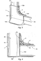
- the connecting device 1 comprises a clamping member 4 having first and second bearing surfaces 4a, 4b shaped to engage respectively in the first and second slots 31a, 31b.
- the first and second bearing surfaces 4a, 4b of the clamping member 4 respectively have an area substantially equal to the area of the first and second slots 31a, 31b.
- the body 10 of the connecting device 1 has a support surface 101 facing the outside of the body 10, the support surface 101 being arranged to support the clamping member 4.
- the support surface 101 is substantially flat so as to define a flat support for the clamping member 4.
- a threaded orifice 102 is formed in the support surface 101.
- the first and second walls 32a, 32b delimit with the support surface 101 a housing shaped so that the clamping member 4 fits into said housing, as visible in FIG. figure 3 .
- the clamping member 4 comprises a substantially flat connecting surface 41 connecting the bearing surfaces 4a, 4b to each other by shoulders 410.
- the shoulders 410 form stop means arranged to abut against the support surface 101 when the clamping member 4 is fitted into the housing.
- the support surface 101 is shaped to cooperate with the connecting surface 41 of the clamping member 4 by complementary shape.
- the clamping member 4 extends in a substantially curvilinear direction to extend the first and second walls 32a, 32b when the clamping member 4 is fitted into the housing.
- an extension ensuring continuity between the first and second walls 32a, 32b and the clamping member 4 makes it possible to confer an aesthetic character on the connection device 1.
- the connecting device 1 comprises fixing means arranged to place the clamping member 4 on the support surface 101 of the body 10 in a fixing position (illustrated in FIGS. Figures 3 and 4 ) in which the first and second bearing surfaces 4a, 4b respectively extend through the first and second lumens 31a, 31b so as to exert pressure on the first and second profiles 2a, 2b respectively when they are received inside the first and second enclosures 3a, 3b.
- each support surface 4a, 4b forms a half-jaw for holding in position the profiles 2a, 2b respectively inside the corresponding chamber 3a, 3b.
- the fixing means comprise a fixing screw 5 shaped to cooperate with the threaded orifice 102 of the support surface 101 so that the fixing screw 5 plates the clamping member 4 in the fixing position against the support surface 101.
- a through hole 40 is formed in the clamping member 4, the through hole 40 being shaped to receive the fixing screw 5.
- the body 10 has a partition 103 arranged to delimit the first and second enclosures 3a, 3b.
- the support surface 101 is mounted on the partition 103, thereby improving its mechanical strength.
- the enclosures 3a, 3b may have different shapes of cross sections shaped to receive different types of profiles 2a, 2b.
Landscapes
- Engineering & Computer Science (AREA)
- Architecture (AREA)
- General Engineering & Computer Science (AREA)
- Physics & Mathematics (AREA)
- Electromagnetism (AREA)
- Civil Engineering (AREA)
- Structural Engineering (AREA)
- Mechanical Engineering (AREA)
- Connection Of Plates (AREA)
- Clamps And Clips (AREA)
Claims (10)
- Verbindungsvorrichtung (1) eines ersten und eines zweiten Profils (2a, 2b), die einen Körper (10) aufweist, der umfasst:- einen ersten und zweiten Raum (3a, 3b), die jeweils eine erste und eine zweite Öffnung (30a, 30b) begrenzen, die dazu bestimmt sind, jeweils das erste und zweite Profil (2a, 2b) aufzunehmen,- einen ersten und zweiten Schlitz (31 a, 31 b), die jeweils in den ersten und zweiten Raum (3a, 3b) münden, wobei die Verbindungsvorrichtung (1) dadurch gekennzeichnet ist, dass sie aufweist:- ein Spannorgan (4), das eine erste und zweite Stützfläche (4a, 4b) aufweist, die ausgebildet sind, um jeweils in den ersten und zweiten Schlitz (31 a, 31 b) einzugreifen,- Befestigungsmittel, die ausgebildet sind, um das Spannorgan (4) auf dem Körper (10) in einer Befestigungsposition zu platzieren, in der sich die erste und zweite Stützfläche (4a, 4b) jeweils durch den ersten und zweiten Schlitz (31 a, 31 b) derart erstrecken, dass ein Druck jeweils auf das erste und zweite Profil (2a, 2b) ausgeübt wird, wenn diese im ersten und zweiten Raum (3a, 3b) aufgenommen sind.
- Verbindungsvorrichtung (1) nach Anspruch 1, dadurch gekennzeichnet, dass der Körper (10) eine Aufnahme begrenzt, die ausgebildet ist, damit das Spannorgan (4) in die Aufnahme einrastet.
- Verbindungsvorrichtung (1) nach einem der Ansprüche 1 und 2, dadurch gekennzeichnet, dass der Körper (10) eine Stützfläche (101) aufweist, die nach außerhalb des Körpers (10) ausgerichtet ist, wobei die Stützfläche ausgebildet ist, um das Spannorgan (4) zu stützen.
- Verbindungsvorrichtung (1) nach Anspruch 3 in Kombination mit Anspruch 2, dadurch gekennzeichnet, dass der erste und zweite Raum (3a, 3b) jeweils eine erste und zweite Wand (32a, 32b) aufweisen, in der jeweils der erste und zweite Schlitz (31 a, 31 b) eingearbeitet ist, und dass die erste und zweite Wand (32a, 32b) mit der Stützfläche (101) die Aufnahme begrenzen.
- Verbindungsvorrichtung (1) nach einem der Ansprüche 3 und 4, dadurch gekennzeichnet, dass die Stützfläche (101) ausgebildet ist, um mit einem Spannorgan (4) durch Formkomplementarität zusammenzuarbeiten.
- Verbindungsvorrichtung (1) nach einem der Ansprüche 3 bis 5, dadurch gekennzeichnet, dass das Spannorgan (4) Anschlagmittel aufweist, die ausgebildet sind, um gegen die Stützfläche (101) anzuschlagen.
- Verbindungsvorrichtung (1) nach einem der Ansprüche 3 bis 6, dadurch gekennzeichnet, dass die Befestigungsmittel eine Befestigungsschraube (5) aufweisen, die ausgebildet ist, um mit der Stützfläche (101) derart zusammenzuarbeiten, dass die Befestigungsschraube (5) das Spannorgan (4) in der Befestigungsposition gegen die Stützfläche (101) drückt.
- Verbindungsvorrichtung (1) nach einem der Ansprüche 3 bis 7, dadurch gekennzeichnet, dass der Körper (10) eine Trennwand (103) aufweist, die ausgebildet ist, um den ersten und zweiten Raum (3a, 3b) zu begrenzen und dass die Stützfläche (101) auf der Trennwand (103) montiert ist.
- Verbindungsvorrichtung (1) nach einem der Ansprüche 1 bis 8, dadurch gekennzeichnet, dass sich der erste und zweite Raum (3a, 3b) jeweils gemäß einer ersten und zweiten Achse (Z'-Z, X'-X) erstrecken, vorzugsweise etwa lotrecht zwischen ihnen.
- Verbindungsvorrichtung (1) nach einem der Ansprüche 1 bis 9, dadurch gekennzeichnet, dass die erste und zweite Stützfläche (4a, 4b) des Spannorgans (4) jeweils eine Oberfläche aufweisen, die etwa gleich der Oberfläche des ersten und zweiten Schlitzes (31 a, 31 b) ist.
Applications Claiming Priority (1)
| Application Number | Priority Date | Filing Date | Title |
|---|---|---|---|
| FR1154281A FR2975459B1 (fr) | 2011-05-17 | 2011-05-17 | Dispositif de raccordement d'un premier et d'un second profile |
Publications (2)
| Publication Number | Publication Date |
|---|---|
| EP2525007A1 EP2525007A1 (de) | 2012-11-21 |
| EP2525007B1 true EP2525007B1 (de) | 2013-11-20 |
Family
ID=46027866
Family Applications (1)
| Application Number | Title | Priority Date | Filing Date |
|---|---|---|---|
| EP12167917.9A Not-in-force EP2525007B1 (de) | 2011-05-17 | 2012-05-14 | Verbindungsvorrichtung zwischen zwei Proflen |
Country Status (2)
| Country | Link |
|---|---|
| EP (1) | EP2525007B1 (de) |
| FR (1) | FR2975459B1 (de) |
Family Cites Families (4)
| Publication number | Priority date | Publication date | Assignee | Title |
|---|---|---|---|---|
| US2417654A (en) * | 1945-05-04 | 1947-03-18 | Excel Corp | Joint for tubes, rods, and the like |
| US2711916A (en) * | 1951-01-19 | 1955-06-28 | Azzo Errol P D | Pipe fitting for awning arms and the like |
| FR2542046B1 (fr) * | 1983-01-13 | 1985-11-29 | Atal | Dispositif d'angle destine a l'assemblage d'un triedre de trois tubes |
| GB0122128D0 (en) * | 2001-09-13 | 2001-10-31 | Kee Klamp Ltd | A connector for a modular safety rail |
-
2011
- 2011-05-17 FR FR1154281A patent/FR2975459B1/fr not_active Expired - Fee Related
-
2012
- 2012-05-14 EP EP12167917.9A patent/EP2525007B1/de not_active Not-in-force
Also Published As
| Publication number | Publication date |
|---|---|
| FR2975459B1 (fr) | 2013-06-28 |
| FR2975459A1 (fr) | 2012-11-23 |
| EP2525007A1 (de) | 2012-11-21 |
Similar Documents
| Publication | Publication Date | Title |
|---|---|---|
| FR2972574A1 (fr) | Procede de mise a la terre d'une installation electrique et dispositif de connexion pour la mise en oeuvre dudit procede | |
| EP2795141B1 (de) | System zum befestigen eines objekts an einem element mit befestigungsrille(n) und befestigungsvorrichtung für ein solches system | |
| EP0494122A1 (de) | Gelenkaufhängeelement | |
| FR2731496A1 (fr) | Dispositif de raccordement d'angle pour conduit a corps en gouttiere et couvercle tel que moulure, plinthe ou goulotte, notamment pour appareillage electrique | |
| EP2525007B1 (de) | Verbindungsvorrichtung zwischen zwei Proflen | |
| EP0274926A1 (de) | Einrichtung zur Zusammensetzung von Platten in verschiedenen winkligen Lagen sowie für die Verwendung dieser Einrichtung geeignete Platten | |
| EP3286497B1 (de) | Planare montagevorrichtung mit beleuchtung | |
| FR2954011A1 (fr) | Accessoire de montage d'un ou plusieurs cables electriques ou similaires sur un element comprenant au moins une gorge retentive | |
| FR2974612A1 (fr) | Dispositif de fixation et de raccordement d'un organe d'alimentation d'appareil sanitaire sur une paroi et son procede de montage | |
| EP0259199B1 (de) | Elektrische Verbindungsanordnung für einen Lautsprechermotor | |
| EP2658057B1 (de) | Befestigungsvorrichtung zur Montage eines Elektrogeräteelements im Innern einer Öffnung in einer Einbauwand und Gesamtheit dieser Befestigungsvorrichtungen | |
| FR2925418A1 (fr) | Boitier de feu de signalisation d'un vehicule automobile avec fixation centrale par le connecteur du porte-lampe | |
| FR2677084A1 (fr) | Dispositif d'assemblage pour profiles creux. | |
| EP0744088A1 (de) | Elektrische stecker in englischer ausführung | |
| EP2636816B1 (de) | Anordnung zur Verkleidung einer Wand | |
| FR2607327A1 (fr) | Dispositif de connexion electrique, en particulier pour afficheurs a cristaux liquides | |
| EP3319835A1 (de) | Beleuchtungsvorrichtungselement zur reduzierung der wasserretention in der nähe einer dichtung | |
| EP1557502B1 (de) | Umkehrbares Solidarisierungselement, Bretter und Ordnen, die solche Elemente verwirklichen | |
| EP4127351B1 (de) | Rahmenteil zur herstellung einer hinterleuchteten blindwand und eine solche hinterleuchtete blindwand | |
| EP2116446B1 (de) | Befestigungshalterung eines Verkleidungselements eines Fahrzeugkarosserieteils, entsprechendes Verkleidungselement und Verwendung dieser Befestigungshalterung | |
| EP0985834B1 (de) | Vorrichtung in Form einer Platte zum Befestigen mindestens eines Teils auf einem anderen | |
| EP1564860B1 (de) | Wanddickeanpassungsflanschgehäuse für eine dünne Wand | |
| EP0172779A1 (de) | Mehrpoliger elektrischer Verbinder | |
| FR3156863A1 (fr) | Dispositif de fixation pour élément de vitrage | |
| FR3027166A1 (fr) | Panneau de disjoncteurs |
Legal Events
| Date | Code | Title | Description |
|---|---|---|---|
| PUAI | Public reference made under article 153(3) epc to a published international application that has entered the european phase |
Free format text: ORIGINAL CODE: 0009012 |
|
| AK | Designated contracting states |
Kind code of ref document: A1 Designated state(s): AL AT BE BG CH CY CZ DE DK EE ES FI FR GB GR HR HU IE IS IT LI LT LU LV MC MK MT NL NO PL PT RO RS SE SI SK SM TR |
|
| AX | Request for extension of the european patent |
Extension state: BA ME |
|
| 17P | Request for examination filed |
Effective date: 20130325 |
|
| RIC1 | Information provided on ipc code assigned before grant |
Ipc: F16B 7/04 20060101ALI20130416BHEP Ipc: E04G 21/32 20060101ALI20130416BHEP Ipc: E04B 1/58 20060101AFI20130416BHEP |
|
| GRAP | Despatch of communication of intention to grant a patent |
Free format text: ORIGINAL CODE: EPIDOSNIGR1 |
|
| INTG | Intention to grant announced |
Effective date: 20130628 |
|
| GRAS | Grant fee paid |
Free format text: ORIGINAL CODE: EPIDOSNIGR3 |
|
| GRAA | (expected) grant |
Free format text: ORIGINAL CODE: 0009210 |
|
| AK | Designated contracting states |
Kind code of ref document: B1 Designated state(s): AL AT BE BG CH CY CZ DE DK EE ES FI FR GB GR HR HU IE IS IT LI LT LU LV MC MK MT NL NO PL PT RO RS SE SI SK SM TR |
|
| REG | Reference to a national code |
Ref country code: GB Ref legal event code: FG4D Free format text: NOT ENGLISH |
|
| REG | Reference to a national code |
Ref country code: CH Ref legal event code: EP |
|
| REG | Reference to a national code |
Ref country code: AT Ref legal event code: REF Ref document number: 641755 Country of ref document: AT Kind code of ref document: T Effective date: 20131215 |
|
| REG | Reference to a national code |
Ref country code: IE Ref legal event code: FG4D Free format text: LANGUAGE OF EP DOCUMENT: FRENCH |
|
| REG | Reference to a national code |
Ref country code: DE Ref legal event code: R096 Ref document number: 602012000542 Country of ref document: DE Effective date: 20140116 |
|
| REG | Reference to a national code |
Ref country code: NL Ref legal event code: T3 |
|
| REG | Reference to a national code |
Ref country code: LT Ref legal event code: MG4D |
|
| PG25 | Lapsed in a contracting state [announced via postgrant information from national office to epo] |
Ref country code: IS Free format text: LAPSE BECAUSE OF FAILURE TO SUBMIT A TRANSLATION OF THE DESCRIPTION OR TO PAY THE FEE WITHIN THE PRESCRIBED TIME-LIMIT Effective date: 20140320 Ref country code: FI Free format text: LAPSE BECAUSE OF FAILURE TO SUBMIT A TRANSLATION OF THE DESCRIPTION OR TO PAY THE FEE WITHIN THE PRESCRIBED TIME-LIMIT Effective date: 20131120 Ref country code: NO Free format text: LAPSE BECAUSE OF FAILURE TO SUBMIT A TRANSLATION OF THE DESCRIPTION OR TO PAY THE FEE WITHIN THE PRESCRIBED TIME-LIMIT Effective date: 20140220 Ref country code: HR Free format text: LAPSE BECAUSE OF FAILURE TO SUBMIT A TRANSLATION OF THE DESCRIPTION OR TO PAY THE FEE WITHIN THE PRESCRIBED TIME-LIMIT Effective date: 20131120 Ref country code: SE Free format text: LAPSE BECAUSE OF FAILURE TO SUBMIT A TRANSLATION OF THE DESCRIPTION OR TO PAY THE FEE WITHIN THE PRESCRIBED TIME-LIMIT Effective date: 20131120 Ref country code: LT Free format text: LAPSE BECAUSE OF FAILURE TO SUBMIT A TRANSLATION OF THE DESCRIPTION OR TO PAY THE FEE WITHIN THE PRESCRIBED TIME-LIMIT Effective date: 20131120 |
|
| PG25 | Lapsed in a contracting state [announced via postgrant information from national office to epo] |
Ref country code: RS Free format text: LAPSE BECAUSE OF FAILURE TO SUBMIT A TRANSLATION OF THE DESCRIPTION OR TO PAY THE FEE WITHIN THE PRESCRIBED TIME-LIMIT Effective date: 20131120 Ref country code: LV Free format text: LAPSE BECAUSE OF FAILURE TO SUBMIT A TRANSLATION OF THE DESCRIPTION OR TO PAY THE FEE WITHIN THE PRESCRIBED TIME-LIMIT Effective date: 20131120 Ref country code: ES Free format text: LAPSE BECAUSE OF FAILURE TO SUBMIT A TRANSLATION OF THE DESCRIPTION OR TO PAY THE FEE WITHIN THE PRESCRIBED TIME-LIMIT Effective date: 20131120 |
|
| PG25 | Lapsed in a contracting state [announced via postgrant information from national office to epo] |
Ref country code: PT Free format text: LAPSE BECAUSE OF FAILURE TO SUBMIT A TRANSLATION OF THE DESCRIPTION OR TO PAY THE FEE WITHIN THE PRESCRIBED TIME-LIMIT Effective date: 20140320 |
|
| PG25 | Lapsed in a contracting state [announced via postgrant information from national office to epo] |
Ref country code: EE Free format text: LAPSE BECAUSE OF FAILURE TO SUBMIT A TRANSLATION OF THE DESCRIPTION OR TO PAY THE FEE WITHIN THE PRESCRIBED TIME-LIMIT Effective date: 20131120 |
|
| REG | Reference to a national code |
Ref country code: DE Ref legal event code: R097 Ref document number: 602012000542 Country of ref document: DE |
|
| PG25 | Lapsed in a contracting state [announced via postgrant information from national office to epo] |
Ref country code: SK Free format text: LAPSE BECAUSE OF FAILURE TO SUBMIT A TRANSLATION OF THE DESCRIPTION OR TO PAY THE FEE WITHIN THE PRESCRIBED TIME-LIMIT Effective date: 20131120 Ref country code: PL Free format text: LAPSE BECAUSE OF FAILURE TO SUBMIT A TRANSLATION OF THE DESCRIPTION OR TO PAY THE FEE WITHIN THE PRESCRIBED TIME-LIMIT Effective date: 20131120 Ref country code: CZ Free format text: LAPSE BECAUSE OF FAILURE TO SUBMIT A TRANSLATION OF THE DESCRIPTION OR TO PAY THE FEE WITHIN THE PRESCRIBED TIME-LIMIT Effective date: 20131120 Ref country code: RO Free format text: LAPSE BECAUSE OF FAILURE TO SUBMIT A TRANSLATION OF THE DESCRIPTION OR TO PAY THE FEE WITHIN THE PRESCRIBED TIME-LIMIT Effective date: 20131120 |
|
| PLBE | No opposition filed within time limit |
Free format text: ORIGINAL CODE: 0009261 |
|
| STAA | Information on the status of an ep patent application or granted ep patent |
Free format text: STATUS: NO OPPOSITION FILED WITHIN TIME LIMIT |
|
| PG25 | Lapsed in a contracting state [announced via postgrant information from national office to epo] |
Ref country code: DK Free format text: LAPSE BECAUSE OF FAILURE TO SUBMIT A TRANSLATION OF THE DESCRIPTION OR TO PAY THE FEE WITHIN THE PRESCRIBED TIME-LIMIT Effective date: 20131120 |
|
| PGFP | Annual fee paid to national office [announced via postgrant information from national office to epo] |
Ref country code: BE Payment date: 20140527 Year of fee payment: 3 |
|
| 26N | No opposition filed |
Effective date: 20140821 |
|
| REG | Reference to a national code |
Ref country code: DE Ref legal event code: R097 Ref document number: 602012000542 Country of ref document: DE Effective date: 20140821 |
|
| PG25 | Lapsed in a contracting state [announced via postgrant information from national office to epo] |
Ref country code: LU Free format text: LAPSE BECAUSE OF FAILURE TO SUBMIT A TRANSLATION OF THE DESCRIPTION OR TO PAY THE FEE WITHIN THE PRESCRIBED TIME-LIMIT Effective date: 20140514 |
|
| PG25 | Lapsed in a contracting state [announced via postgrant information from national office to epo] |
Ref country code: MC Free format text: LAPSE BECAUSE OF FAILURE TO SUBMIT A TRANSLATION OF THE DESCRIPTION OR TO PAY THE FEE WITHIN THE PRESCRIBED TIME-LIMIT Effective date: 20131120 |
|
| REG | Reference to a national code |
Ref country code: IE Ref legal event code: MM4A |
|
| PG25 | Lapsed in a contracting state [announced via postgrant information from national office to epo] |
Ref country code: SI Free format text: LAPSE BECAUSE OF FAILURE TO SUBMIT A TRANSLATION OF THE DESCRIPTION OR TO PAY THE FEE WITHIN THE PRESCRIBED TIME-LIMIT Effective date: 20131120 |
|
| PG25 | Lapsed in a contracting state [announced via postgrant information from national office to epo] |
Ref country code: IE Free format text: LAPSE BECAUSE OF NON-PAYMENT OF DUE FEES Effective date: 20140514 |
|
| REG | Reference to a national code |
Ref country code: CH Ref legal event code: PL |
|
| PG25 | Lapsed in a contracting state [announced via postgrant information from national office to epo] |
Ref country code: LI Free format text: LAPSE BECAUSE OF NON-PAYMENT OF DUE FEES Effective date: 20150531 Ref country code: CH Free format text: LAPSE BECAUSE OF NON-PAYMENT OF DUE FEES Effective date: 20150531 |
|
| REG | Reference to a national code |
Ref country code: FR Ref legal event code: PLFP Year of fee payment: 5 |
|
| PG25 | Lapsed in a contracting state [announced via postgrant information from national office to epo] |
Ref country code: MT Free format text: LAPSE BECAUSE OF FAILURE TO SUBMIT A TRANSLATION OF THE DESCRIPTION OR TO PAY THE FEE WITHIN THE PRESCRIBED TIME-LIMIT Effective date: 20131120 |
|
| PG25 | Lapsed in a contracting state [announced via postgrant information from national office to epo] |
Ref country code: SM Free format text: LAPSE BECAUSE OF FAILURE TO SUBMIT A TRANSLATION OF THE DESCRIPTION OR TO PAY THE FEE WITHIN THE PRESCRIBED TIME-LIMIT Effective date: 20131120 |
|
| PGFP | Annual fee paid to national office [announced via postgrant information from national office to epo] |
Ref country code: NL Payment date: 20160329 Year of fee payment: 5 |
|
| PG25 | Lapsed in a contracting state [announced via postgrant information from national office to epo] |
Ref country code: BG Free format text: LAPSE BECAUSE OF FAILURE TO SUBMIT A TRANSLATION OF THE DESCRIPTION OR TO PAY THE FEE WITHIN THE PRESCRIBED TIME-LIMIT Effective date: 20131120 Ref country code: GR Free format text: LAPSE BECAUSE OF FAILURE TO SUBMIT A TRANSLATION OF THE DESCRIPTION OR TO PAY THE FEE WITHIN THE PRESCRIBED TIME-LIMIT Effective date: 20140221 Ref country code: CY Free format text: LAPSE BECAUSE OF FAILURE TO SUBMIT A TRANSLATION OF THE DESCRIPTION OR TO PAY THE FEE WITHIN THE PRESCRIBED TIME-LIMIT Effective date: 20131120 |
|
| PG25 | Lapsed in a contracting state [announced via postgrant information from national office to epo] |
Ref country code: HU Free format text: LAPSE BECAUSE OF FAILURE TO SUBMIT A TRANSLATION OF THE DESCRIPTION OR TO PAY THE FEE WITHIN THE PRESCRIBED TIME-LIMIT; INVALID AB INITIO Effective date: 20120514 Ref country code: TR Free format text: LAPSE BECAUSE OF FAILURE TO SUBMIT A TRANSLATION OF THE DESCRIPTION OR TO PAY THE FEE WITHIN THE PRESCRIBED TIME-LIMIT Effective date: 20131120 |
|
| PGFP | Annual fee paid to national office [announced via postgrant information from national office to epo] |
Ref country code: IT Payment date: 20160513 Year of fee payment: 5 |
|
| REG | Reference to a national code |
Ref country code: FR Ref legal event code: PLFP Year of fee payment: 6 |
|
| PGFP | Annual fee paid to national office [announced via postgrant information from national office to epo] |
Ref country code: FR Payment date: 20170316 Year of fee payment: 6 |
|
| PGFP | Annual fee paid to national office [announced via postgrant information from national office to epo] |
Ref country code: GB Payment date: 20170316 Year of fee payment: 6 |
|
| PG25 | Lapsed in a contracting state [announced via postgrant information from national office to epo] |
Ref country code: BE Free format text: LAPSE BECAUSE OF NON-PAYMENT OF DUE FEES Effective date: 20150531 |
|
| PGFP | Annual fee paid to national office [announced via postgrant information from national office to epo] |
Ref country code: DE Payment date: 20170320 Year of fee payment: 6 |
|
| REG | Reference to a national code |
Ref country code: NL Ref legal event code: MM Effective date: 20170601 |
|
| PG25 | Lapsed in a contracting state [announced via postgrant information from national office to epo] |
Ref country code: NL Free format text: LAPSE BECAUSE OF NON-PAYMENT OF DUE FEES Effective date: 20170601 |
|
| PG25 | Lapsed in a contracting state [announced via postgrant information from national office to epo] |
Ref country code: IT Free format text: LAPSE BECAUSE OF NON-PAYMENT OF DUE FEES Effective date: 20170514 |
|
| PG25 | Lapsed in a contracting state [announced via postgrant information from national office to epo] |
Ref country code: MK Free format text: LAPSE BECAUSE OF FAILURE TO SUBMIT A TRANSLATION OF THE DESCRIPTION OR TO PAY THE FEE WITHIN THE PRESCRIBED TIME-LIMIT Effective date: 20131120 |
|
| REG | Reference to a national code |
Ref country code: AT Ref legal event code: MM01 Ref document number: 641755 Country of ref document: AT Kind code of ref document: T Effective date: 20170514 |
|
| PG25 | Lapsed in a contracting state [announced via postgrant information from national office to epo] |
Ref country code: AT Free format text: LAPSE BECAUSE OF NON-PAYMENT OF DUE FEES Effective date: 20170514 |
|
| PG25 | Lapsed in a contracting state [announced via postgrant information from national office to epo] |
Ref country code: AL Free format text: LAPSE BECAUSE OF FAILURE TO SUBMIT A TRANSLATION OF THE DESCRIPTION OR TO PAY THE FEE WITHIN THE PRESCRIBED TIME-LIMIT Effective date: 20131120 |
|
| REG | Reference to a national code |
Ref country code: DE Ref legal event code: R119 Ref document number: 602012000542 Country of ref document: DE |
|
| GBPC | Gb: european patent ceased through non-payment of renewal fee |
Effective date: 20180514 |
|
| PG25 | Lapsed in a contracting state [announced via postgrant information from national office to epo] |
Ref country code: FR Free format text: LAPSE BECAUSE OF NON-PAYMENT OF DUE FEES Effective date: 20180531 Ref country code: DE Free format text: LAPSE BECAUSE OF NON-PAYMENT OF DUE FEES Effective date: 20181201 Ref country code: GB Free format text: LAPSE BECAUSE OF NON-PAYMENT OF DUE FEES Effective date: 20180514 |