EP2525009A1 - Panneau - Google Patents
Panneau Download PDFInfo
- Publication number
- EP2525009A1 EP2525009A1 EP11732917A EP11732917A EP2525009A1 EP 2525009 A1 EP2525009 A1 EP 2525009A1 EP 11732917 A EP11732917 A EP 11732917A EP 11732917 A EP11732917 A EP 11732917A EP 2525009 A1 EP2525009 A1 EP 2525009A1
- Authority
- EP
- European Patent Office
- Prior art keywords
- protrusions
- panel
- recesses
- section area
- rigidity
- Prior art date
- Legal status (The legal status is an assumption and is not a legal conclusion. Google has not performed a legal analysis and makes no representation as to the accuracy of the status listed.)
- Withdrawn
Links
Images


Classifications
-
- E—FIXED CONSTRUCTIONS
- E04—BUILDING
- E04C—STRUCTURAL ELEMENTS; BUILDING MATERIALS
- E04C2/00—Building elements of relatively thin form for the construction of parts of buildings, e.g. sheet materials, slabs, or panels
- E04C2/30—Building elements of relatively thin form for the construction of parts of buildings, e.g. sheet materials, slabs, or panels characterised by the shape or structure
- E04C2/32—Building elements of relatively thin form for the construction of parts of buildings, e.g. sheet materials, slabs, or panels characterised by the shape or structure formed of corrugated or otherwise indented sheet-like material; composed of such layers with or without layers of flat sheet-like material
- E04C2/326—Building elements of relatively thin form for the construction of parts of buildings, e.g. sheet materials, slabs, or panels characterised by the shape or structure formed of corrugated or otherwise indented sheet-like material; composed of such layers with or without layers of flat sheet-like material with corrugations, incisions or reliefs in more than one direction of the element
-
- E—FIXED CONSTRUCTIONS
- E04—BUILDING
- E04C—STRUCTURAL ELEMENTS; BUILDING MATERIALS
- E04C2/00—Building elements of relatively thin form for the construction of parts of buildings, e.g. sheet materials, slabs, or panels
- E04C2/30—Building elements of relatively thin form for the construction of parts of buildings, e.g. sheet materials, slabs, or panels characterised by the shape or structure
- E04C2/32—Building elements of relatively thin form for the construction of parts of buildings, e.g. sheet materials, slabs, or panels characterised by the shape or structure formed of corrugated or otherwise indented sheet-like material; composed of such layers with or without layers of flat sheet-like material
-
- Y—GENERAL TAGGING OF NEW TECHNOLOGICAL DEVELOPMENTS; GENERAL TAGGING OF CROSS-SECTIONAL TECHNOLOGIES SPANNING OVER SEVERAL SECTIONS OF THE IPC; TECHNICAL SUBJECTS COVERED BY FORMER USPC CROSS-REFERENCE ART COLLECTIONS [XRACs] AND DIGESTS
- Y10—TECHNICAL SUBJECTS COVERED BY FORMER USPC
- Y10T—TECHNICAL SUBJECTS COVERED BY FORMER US CLASSIFICATION
- Y10T428/00—Stock material or miscellaneous articles
- Y10T428/24—Structurally defined web or sheet [e.g., overall dimension, etc.]
- Y10T428/24479—Structurally defined web or sheet [e.g., overall dimension, etc.] including variation in thickness
-
- Y—GENERAL TAGGING OF NEW TECHNOLOGICAL DEVELOPMENTS; GENERAL TAGGING OF CROSS-SECTIONAL TECHNOLOGIES SPANNING OVER SEVERAL SECTIONS OF THE IPC; TECHNICAL SUBJECTS COVERED BY FORMER USPC CROSS-REFERENCE ART COLLECTIONS [XRACs] AND DIGESTS
- Y10—TECHNICAL SUBJECTS COVERED BY FORMER USPC
- Y10T—TECHNICAL SUBJECTS COVERED BY FORMER US CLASSIFICATION
- Y10T428/00—Stock material or miscellaneous articles
- Y10T428/24—Structurally defined web or sheet [e.g., overall dimension, etc.]
- Y10T428/24628—Nonplanar uniform thickness material
- Y10T428/24661—Forming, or cooperating to form cells
-
- Y—GENERAL TAGGING OF NEW TECHNOLOGICAL DEVELOPMENTS; GENERAL TAGGING OF CROSS-SECTIONAL TECHNOLOGIES SPANNING OVER SEVERAL SECTIONS OF THE IPC; TECHNICAL SUBJECTS COVERED BY FORMER USPC CROSS-REFERENCE ART COLLECTIONS [XRACs] AND DIGESTS
- Y10—TECHNICAL SUBJECTS COVERED BY FORMER USPC
- Y10T—TECHNICAL SUBJECTS COVERED BY FORMER US CLASSIFICATION
- Y10T428/00—Stock material or miscellaneous articles
- Y10T428/24—Structurally defined web or sheet [e.g., overall dimension, etc.]
- Y10T428/24628—Nonplanar uniform thickness material
- Y10T428/24669—Aligned or parallel nonplanarities
- Y10T428/24678—Waffle-form
Definitions
- the present invention relates to a panel, in more detail, a panel which is formed in an overall plate shape, and which has, at least on one of the surfaces thereof, a plurality of protruding protrusions.
- Patent Document 1 As an interior panel to be used for transport machinery such as rolling stock, automobiles, aircraft, or ships, and for building structures and the like, there has been proposed a light weight type highly rigid panel having protrusions and recesses provided in a zigzag pattern (for example, refer to Patent Document 1).
- This panel disclosed in Patent Document 1 is such that protrusions and recesses are formed side by side in two directions, namely the vertical direction and horizontal direction of a flat plate panel, and it is formed in a shape such that flat sections other than the protrusions and recesses are not formed linearly.
- Patent Document 1 Japanese Patent Publication No. 2960402
- Patent Document 2 Japanese Unexamined Patent Application, First Publication No. 2008-180125
- protrusions and recesses are provided in a zigzag pattern so that flat sections are not formed linearly, while the flat sections are continuously formed so as to surround these protrusions and recesses. Consequently there is a problem in that these continuous flat sections influence the bending rigidity and torsional rigidity of the entire panel, so that the level of rigidity of the panel cannot be sufficiently increased and the weight thereof cannot be sufficiently reduced.
- An object of the present invention is to provide a panel which has a simple structure and is capable of reliably increasing the level of rigidity thereof and reducing the weight thereof.
- the present invention employs the following measures. That is to say,
- the protrusions, and the flat sections or the recesses are not formed in a planarly continuous manner.
- a three dimensional effect of the panel is obtained in the plate thickness direction, and the bending rigidity and the torsional rigidity of the panel can be improved. Therefore, the level of the rigidity can be improved dramatically, while weight reduction can be realized due to thickness reduction.
- the flat sections when the flat sections are provided, since the entire periphery of each flat section is surrounded by the protrusions, the flat sections are not continuously formed, and the protrusions are not continuously formed.
- the recesses when the recesses are provided, since the entire periphery of each recess is surrounded by the protrusions, the recesses are not continuously formed, and the protrusions are not continuously formed.
- the protrusions, and the flat sections or the recesses geometrically act with respect to bending or torsion of the entire panel, and the level of cross-sectional performance is increased due to the three dimensional effect. Accordingly, it is possible to improve the bending rigidity and the torsional rigidity.
- the predetermined reference surface may be a flat surface, a cylindrical surface, a spherical surface, or any other three-dimensional curved surface.
- the panel may be formed from a flat plate with a predetermined plate thickness through appropriate work processing such as press working and bending, and it may be manufactured integrally with protrusions and flat sections.
- the protrusions, and the flat sections or the recesses are respectively arranged alternately, when a force is applied on the panel, the force can be distributed into two orthogonal directions (widthwise direction and lengthwise direction). As a result, it is possible to further increase the level of rigidity with the entire panel resisting bending and torsion that act on the panel.
- the panel of either one of (3) and (4) above it is possible to increase the level of panel rigidity with a good balance in the directions of the opposite edges and opposite corners of the hexagonal shape.
- the panel of either one of (5) and (6) above it is possible to increase the level of panel rigidity with a good balance in the directions of the opposite edges and opposite corners of the quadrangular shape.
- the panel of (7) above since a bridge is formed between the corner sections of the adjacent protrusions, when a force is applied to the panel, the force is transmitted through this bridge. As a result, stress concentration can be mitigated compared to those cases where adjacent protrusions are directly connected with each other.
- the inclination angle of the protrusion side inclined surface is the same as that of the recess side inclined surface, and the protrusion side inclined surface and the recess side inclined surface are formed continuously, these continuous inclined surfaces function as rib members (reinforcing members). As a result, the level of panel cross-sectional performance can be further increased.
- the neutral axis is positioned in the vicinity of the reference surface, which is at the intermediate part of the panel cross-section.
- a well balanced resistance can be provided with respect to both an external force from the protruding side of the panel and an external force from the recessed side of the panel.
- the panel of (11) above by providing the frame section, it is possible to suppress local deformation in the periphery of the panel and improve the level of panel rigidity.
- a panel 1 (1A to 1E) of the present embodiment is to be used for; packaging for household electric appliances, walls for freight containers, structures and interior/exterior materials for building structures, vehicle bodies, chassis or various components for automobiles, rolling stock, aircraft, and ships, or other types of containers such as cans, and it is formed in an overall plate shape along a predetermined reference surface F of a flat surface or a curved surface.
- This panel 1 may be formed by means of press working with a metal thin plate composed of steel, stainless steel, or an aluminum alloy, and it may also be formed by means of injection molding with a thermoplastic resin.
- the panel 1 is formed so as to have a flat surface section 2 along the reference surface F, and a bent section (frame section) 3 which is bent at a substantially right angle from the outer periphery of this flat surface section 2.
- the panel 1 is provided with the bent section 3, it does not always have to be provided with the bent section 3.
- the bent section 3 it is possible to obtain an effect of suppressing local deformation of the periphery of the panel 1.
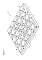
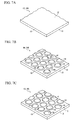
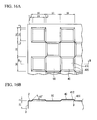
- a panel 1A of a first embodiment shown in FIG. 1 and FIG. 6A is provided with a plurality of protrusions 4A each protruding from the reference surface F, and a plurality of flat sections 5A which are flush with the reference surface F.
- the plurality of protrusions 4A protrude to one side (in the direction perpendicular to the reference surface F: upward from the drawing paper surface).
- the flat sections 5A each include a flat surface section 2, which remains as is and does not protrude.
- the protrusions 4A and the flat sections 5A are arranged side by side along the flat surface section 2.
- Each protrusion 4A is of a regular hexagonal frustrum having an upper surface section 41A in a regular hexagon shape when viewed from the front (when viewed from the protruding direction), and inclined surface sections (inclined surfaces) 42A each extending from each edge of the upper surface section 41A toward the flat surface section 2 (reference surface F).
- Each flat section 5A is formed in a regular triangular shape by the bottom end peripheries of the inclined surface sections 42A of three protrusions 4A. That is to say, the entire periphery of the protrusion 4A is surrounded by the flat sections 5A, and the entire periphery of each flat section 5A is surrounded by the protrusions 4A.
- each flat section 5A the three edges of the entire periphery of each flat section 5A are surrounded by three protrusions 4A, and the six edges of the entire periphery of each protrusion 4A are surrounded by six flat sections 5A. Therefore, the protrusions 4A and the flat sections 5A are arranged so that adjacent flat sections 5A are not formed continuously, and adjacent protrusions 4A are not formed continuously.
- the panel 1A of the present embodiment is of a configuration in which the protrusions 4A and the flat sections 5A are not formed in a planarly continuous manner.
- a three dimensional effect of the panel 1A is obtained in the plate thickness direction, and the bending rigidity and the torsional rigidity of the panel 1A can be improved. Therefore, the level of the rigidity can be improved dramatically, while weight reduction can be realized due to thickness reduction.
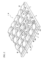
- a panel 1B of a second embodiment shown in FIG. 2 and FIG. 6B is provided with a plurality of protrusions 4B each protruding from the reference surface F, and a plurality of recesses 6B each recessed from the reference surface F.
- the protrusions 4B each protrude to one side (in the direction perpendicular to the reference surface F: upward from the drawing paper surface), and the recesses 6B are each recessed to the other side, which is opposite of the above one side (downward in the drawing).
- the protrusions 4B and the recesses 6B are arranged side by side along the flat surface section 2.
- Each protrusion 4B is of a regular hexagonal frustrum having an upper surface section 41B in a regular hexagon shape when viewed from the front (when viewed from the protruding direction), and inclined surface sections 42B each serving as a side surface thereof.
- This inclined surface section 42B is a protrusion side inclined surface which is formed on the peripheral portion of the protrusion 4B, extends from each edge of the upper surface section 41B toward the flat surface section 2 (reference surface F), and is inclined with respect to the flat surface section 2.
- Each recess 6B is of a downward-facing regular triangular frustrum having a bottom surface section 61B in a regular triangular shape, and inclined surface sections 62B each serving as a side surface thereof.
- the inclined surface section 62B is a recess side inclined surface which is formed on the peripheral portion of the recess 6B, extends from each edge of the bottom surface section 61B toward the flat surface section 2 (reference surface F), and is inclined with respect to the flat surface section 2.
- the entire periphery of each protrusion 4B is surrounded by six of these recesses 6B. Meanwhile, the entire periphery of each recess 6B is surrounded by three of the protrusions 4B.
- the adjacent protrusions 4B are arranged not to be continuous with each other, and the adjacent recesses 6B are arranged not to be continuous with each other.
- an inclination angle ⁇ 1 of the inclined surface section 42B of the protrusion 4B with respect to the reference surface F is the same as an inclination angle ⁇ 2 of the inclined surface section 62B of the recess 6B with respect to the reference surface F.
- these inclined surface section 42B and inclined surface section 62B are linearly continuous and are connected. That is to say, they are formed as being continuous within the same plane.
- the panel 1B of the present embodiment is capable of dramatically increasing the level of rigidity while realizing a reduction in weight as a result of thickness reduction.
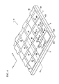
- a panel 1C of a third embodiment shown in FIG. 3 and FIG. 6C is provided with a plurality of protrusions 4C each protruding from the reference surface F, and a plurality of flat sections 5C which are flush with the flat surface section 2.
- the protrusions 4C are each of a quadrangular shape, and protrude to one side (in the direction perpendicular to the reference surface F: upward from the drawing paper surface).
- the flat sections 5C each include a flat surface section 2, which does not protrude and remains as is.
- the protrusions 4C and the flat sections 5C are arranged side by side along the flat surface section 2.
- Each protrusion 4C is of a regular quadrangular frustrum having an upper surface section 41C in a regular quadrangular (tetragonal) shape when viewed from the front (when viewed from the protruding direction), and inclined surface sections (inclined surfaces) 42C each extending from each edge of the upper surface section 41C toward the flat surface section 2 (reference surface F).
- the entire periphery of each flat section 5C is surrounded by the protrusions 4C.
- each flat section 5C is formed in a regular quadrangular shape by the bottom end peripheries of the inclined surface sections 42C of four (three in the case of the periphery of the panel 1) of the protrusions 4C, that is to say, the four edges of the entire periphery of each flat section 5C are surrounded by four of the protrusions 4C. Moreover, the entire periphery of each protrusion 4C is surrounded by the flat sections 5C. With this type of configuration, the protrusions 4C and the flat sections 5C are arranged so that adjacent flat sections 5C are not formed continuously, and adjacent protrusions 4C are not formed continuously.
- the protrusions 4C and the flat sections 5C are arranged alternately along the reference surface F, along the widthwise direction (X direction) and the lengthwise direction (Y direction) orthogonal to this widthwise direction. That is to say, they are formed in a checkered pattern.
- the panel 1C of the present embodiment is capable of dramatically increasing the level of rigidity while realizing a reduction in weight as a result of thickness reduction.
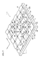
- a panel 1D of a fourth embodiment shown in FIG. 4 and FIG. 6D is provided with a plurality of protrusions 4D each protruding from the reference surface F, and a plurality of recesses 6D each recessed from the reference surface F.
- the protrusions 4D protrude to one side (in the direction perpendicular to the reference surface F: upward from the drawing paper surface).
- the recesses 6D are recessed to the other side, which is opposite of the above one side (downward in the drawing).
- the protrusions 4D and the recesses 6D are arranged side by side along the flat surface section 2.
- Each protrusion 4D is of a regular quadrangular frustrum having an upper surface section 41D in a regular quadrangular (tetragonal) shape when viewed from the front (when viewed from the protruding direction), and inclined surface sections 42D each serving as a side surface thereof.
- the inclined surface section 42D is a protrusion side inclined surface which is formed on the peripheral portion of the protrusion, extends from each edge of the upper surface section 41D toward the flat surface section 2 (reference surface F), and is inclined with respect to the flat surface section 2.
- the entire periphery of each protrusion 4D is surrounded by four of these recesses 6D. Meanwhile, the entire periphery of each recess 6D is surrounded by four of the protrusions 4B.
- Each protrusion 6D is of a downward-facing regular quadrangular frustrum having a bottom surface section 61D in a regular quadrangular (tetragonal) shape when viewed from the front (when viewed from the protruding direction), and inclined surface sections 62D each serving as a side surface thereof.
- the inclined surface section 62D is a recess side inclined surface which is formed on the peripheral portion of the recess 6D, extends from each edge of the bottom surface section 61 D toward the flat surface section 2 (reference surface F), and is inclined with respect to the flat surface section 2.
- each protrusion 4D is surrounded by four of the recesses 6D, while the entire periphery of each recess 6D is surrounded by four of the protrusions 4D.
- the protrusions 4D and the recesses 6D are arranged side by side alternately along the widthwise direction (X direction) and the lengthwise direction (Y direction) orthogonal to this widthwise direction. That is to say, they are formed in a checkered pattern. Accordingly, the adjacent protrusions 4D are arranged not to be continuous with each other, and the adjacent recesses 6D are arranged not to be continuous with each other.
- an inclination angle ⁇ 3 of the inclined surface section 42D of the protrusion 4D with respect to the reference surface F is the same as an inclination angle ⁇ 4 of the inclined surface section 62D of the recess 6D with respect to the reference surface F.
- these inclined surface section 42D and inclined surface section 62D are linearly continuous and are connected. That is to say, they are formed as being continuous within the same plane.
- the panel 1D of the present embodiment is capable of dramatically increasing the level of rigidity while realizing a reduction in weight as a result of thickness reduction.
- a panel 1E of a fifth embodiment shown in FIG. 5 and FIG. 6E is provided with a plurality of protrusions 4E each protruding from the reference surface F, and a plurality of recesses 6E each recessed from the reference surface F.
- the protrusions 4E protrude to one side (in the direction perpendicular to the reference surface F: upward from the drawing paper surface).
- the recesses 6E are recessed to the other side, which is opposite of the above one side (downward in the drawing).
- the protrusions 4E and the recesses 6E are arranged side by side along the flat surface section 2. Moreover, between corner sections of the adjacent protrusions 4E (between corner sections of the recesses 6E), there is formed a bridge 51E.
- Each bridge 51E has a flat top flat section (top upper surface) 5E, and this top flat section 5E is formed with a flat surface section 2 which remains as is and does not protrude nor is recessed.
- Each protrusion 4E is of an octangular frustrum having a regular-quadrangular-shaped (tetragonal) upper surface section 41 E, four corners of which are chamfered, when viewed from the front (when viewed from the protruding direction), inclined surface sections 42E each serving as a side surface, and corner section inclined surfaces 43 E each extending from the four corners of the upper surface section 41E toward the flat surface section 2 (reference surface F).
- This inclined surface section 42E is a protrusion side inclined surface which is formed on the peripheral portion of the protrusion 4E, extends from each edge of the upper surface section 41E toward the flat surface section 2 (reference surface F), and is inclined with respect to the flat surface section 2.
- Each recess 6E is of a downward-facing octangular frustrum having a regular-quadrangular-shaped bottom surface section 61 E, four corners of which are chamfered, when viewed from the front (when viewed from the protruding direction), inclined surface sections 62E each serving as a side surface, and corner section inclined surfaces 63E each extending from the four corners of the bottom surface section 61E toward the flat surface section 2 (reference surface F).
- the inclined surface section 62E is a recess side inclined surface which is formed on the peripheral portion of the recess 6E, extends from each edge of the bottom surface section 61E toward the flat surface section 2 (reference surface F), and is inclined with respect to the flat surface section 2.
- Each top flat section 5E is formed, in a corner section where diagonally positioned two protrusions 4E and two recesses 6E approach to each other, in a regular quadrangular shape defined by the bottom end peripheries of the corner section inclined surfaces 43E and the upper end peripheries of the corner section inclined surfaces 63E.
- each protrusion 4E is surrounded by four of the recesses 6E, and the entire periphery of each recess 6E is surrounded by four of the protrusions 4E.
- the protrusions 4E and the recesses 6E are arranged side by side alternately along the widthwise direction (X direction) and the lengthwise direction (Y direction) orthogonal to this widthwise direction. That is to say, they are formed in a checkered pattern.
- the panel 1E is configured such that the adjacent protrusions 4E are arranged not to be continuous with each other, and the adjacent recesses 6E are arranged not to be continuous with each other.
- an inclination angle ⁇ 5 of the inclined surface section 42E of the protrusion 4E with respect to the reference surface F is the same as an inclination angle ⁇ 6 of the inclined surface section 62E of the recess 6E with respect to the reference surface F.
- the inclined surface section 42E and the inclined surface section 62E are formed as being continuous within the same plane.
- the panel 1E of the present embodiment is capable of dramatically increasing the level of rigidity while realizing a reduction in weight as a result of thickness reduction.
- the panels 1A to 1D of FIG. 1 to FIG. 4 may be provided with bridges 51E as with those of the panel 1E.
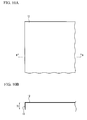
- FIG. 7A the panel 10A is formed having a flat-plate-shaped flat surface section 12, and bent sections 13 each bent substantially at right angles from the outer periphery of this flat surface section 12.
- FIG. 7B the panel 10B is formed having a flat surface section 12, bent sections 13, a plurality of protrusions 14 each protruding to one side (upward from the drawing paper surface) from the flat surface section 12, and a flat section 15 where no protrusion 14 is formed on the flat surface section 12.
- the panel 10C is formed having a flat surface section 12, bent sections 13, a plurality of protrusions 14, a flat section 15, and a plurality of recesses 16 each recessed from the flat surface section 12 to the other side (downward in the drawing).
- the panel 10D is formed having a flat surface section 12, bent sections 13, and a plurality of protrusions 14D each protruding from the flat surface section 12 to one side (upward from the drawing paper surface), and the protrusions 14D are each of a quadrangular pyramid in a planarly regular quadrangular shape and are arranged side by side so that the edges of the adjacent protrusions 14D are in contact with each other.
- each model was of a configuration such that the height of each bent section 3 and 13 was 15 mm, and end peripheries 23 thereof were not connected with each other. Furthermore, the arrangement and the dimension of protrusions and recesses of each model are shown in FIG. 10A to FIG. 18B . The model dimensions are each expressed as a dimension at the plate thickness center of the panels 1 and 10. Moreover, analysis results are shown in FIG. 19 and FIG. 20 .
- Comparative Example 1 uses a panel 10A shown in FIG. 7A , and the shape of the analysis model is shown in FIG. 10 . Moreover, it is shown as No. 1 in the analysis result graphs ( FIG. 19 and FIG. 20 ). Comparative Example 2 uses a panel 10B shown in FIG. 7B , and the arrangement and dimensions of protrusions and recesses of the analysis model are shown in FIG. 11A and FIG. 11B . Moreover, it is shown as No. 2 in the analysis result graphs ( FIG. 19 and FIG. 20 ). In this Comparative Example 2, there is made an arrangement such that the distance between the centers of adjacent protrusions 14 is 34.64 mm, and the center point is positioned at the apex of an equilateral triangle.
- each protrusion 14 The diameter of the truncated cone top surface of each protrusion 14 is 24 mm, the diameter of the truncated cone bottom surface is 30 mm, the protrusion dimension of the protrusion 14 from the flat surface section 12 is 3 mm, and the inclination angle of the truncated cone of the protrusion 14 is 45°.
- Comparative Example 3 uses a panel 10C shown in FIG. 7C , and the arrangement and dimensions of protrusions and recesses of the analysis model are shown in FIG. 12A and FIG. 12B . Moreover, it is shown as No. 3 in the analysis result graphs ( FIG. 19 and FIG. 20 ).
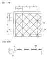
- Comparative Example 4 uses a panel 10D shown in FIG. 8 , and the arrangement and dimensions of protrusions and recesses of the analysis model are shown in FIG. 13A and FIG. 13B . Moreover, it is shown as No. 4 in the analysis result graphs ( FIG. 19 and FIG. 20 ).
- the distance between the centers of adjacent protrusions 14D is 30 mm, that is to say, the planar dimension of each protrusion 14D is 30 mm ⁇ 30 mm, and the protrusion dimension of the protrusion 14D from the flat surface section 12, that is, the height of the apex of the quadrangular pyramid is 3 mm.
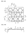
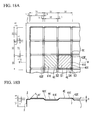
- Example 1 uses a panel 1A shown in FIG. 1 and FIG. 6A , and the arrangement and dimensions of protrusions and recesses of the analysis model are shown in FIG. 14A and FIG. 14B . Moreover, it is shown as No. 5 in the analysis result graphs ( FIG. 19 and FIG. 20 ).
- Example 1 the distance between the centers of adjacent protrusions 4A is 34.64 mm, the center point is positioned at the apex of an equilateral triangle, the distance between the opposite edges of the hexagonal frustrum top surface of each protrusion 4A is 24 mm, the distance between the opposite edges of the hexagonal frustrum bottom surface is 30 mm, and the flat surface equilateral triangle surrounded by hexagonal frustrum bottom surfaces serves as each flat section 5A. Furthermore, the protrusion dimension of the protrusion 4A from the flat surface section 2 is 3 mm, and the inclination angle of the inclined surface section 42A of each protrusion 4A with respect to the reference surface F is 45°.
- Example 2 uses a panel 1B shown in FIG. 2 and FIG.
- FIG. 15A and FIG. 15B the arrangement and dimensions of protrusions and recesses of the analysis model are shown in FIG. 15A and FIG. 15B . Moreover, it is shown as No. 6 in the analysis result graphs ( FIG. 19 and FIG. 20 ).
- the distance between the centers of adjacent protrusions 4B is 34.64 mm, and the center point is positioned at the apex of the equilateral triangle, the distance between the opposite edges of the hexagonal frustrum top surface of each protrusion 4B is 27 mm, and the distance between the opposite edges of the hexagonal frustrum bottom surface is 30 mm.
- each protrusion dimension of each protrusion 4B from the flat surface section 2 is 1.5 mm
- the recess dimension of each recess 6B from the flat surface section 2 is 1.5 mm
- the distance between the hexagonal frustrum top surface of each protrusion 4B and the triangular frustrum top surface of each recess 6B is 3 mm
- the inclination angles of the inclined surface section 42B of the protrusion 4A and the inclination angle of the inclined surface section 62B of the recess 6B with respect to the reference surface F are respectively 45°.
- Example 3 uses a panel 1C shown in FIG. 3 and FIG. 6C , and the arrangement and dimensions of protrusions and recesses of the analysis model are shown in FIG. 16A and FIG. 16B . Moreover, it is shown as No. 7 in the analysis result graphs ( FIG. 19 and FIG. 20 ).
- the distance between the centers of adjacent protrusions 4C is 30 mm, that is to say, the length of each edge of the quadrangular frustrum bottom surface of each protrusion 4C is 30 mm, and the length of each edge of the quadrangular frustrum top surface is 24 mm.
- Example 4 uses a panel 1D shown in FIG. 4 and FIG. 6D , and the arrangement and dimensions of protrusions and recesses of the analysis model are shown in FIG. 17A and FIG. 17B . Moreover, it is shown as No. 8 in the analysis result graphs ( FIG. 19 and FIG. 20 ).
- the distance between the centers of adjacent protrusions 4D is 30 mm, that is to say, the length of each edge of the quadrangular frustrum bottom surface of each planarly regular-quadrangular-shaped protrusion 4D is 30 mm, the length of each edge of the quadrangular frustrum top surface thereof is 27 mm, the length of each edge of the quadrangular frustrum bottom surface of each recess 6D is 30 mm, and the length of each edge of the quadrangular frustrum top surface thereof is 27 mm. Furthermore, the protrusion dimension of each protrusion 4D from the flat surface section 2 is 1.5 mm, and the recess dimension of each recess 6D from the flat surface section 2 is 1.5 mm.
- the distance between the quadrangular frustrum top surface of each protrusion 4D and the quadrangular frustrum top surface of each recess 6D is 3 mm, and the inclination angle of the inclined surface section 42D of the protrusion 4D and the inclination angle of the inclined surface section 62D of the recess 6D with respect to the reference surface F are respectively 45°.
- the planar shapes and the planar dimensions of the protrusion 4D and the recess 6D are the same. As a result, a well balanced resistance can be provided with respect to both an external force from the protruding side of the panel and an external force from the recessed side of the panel.
- the protrusion dimension of the protrusion and the recess dimension of the recess perpendicular to the reference surface are the same. Also in this case, a well balanced resistance can be provided with respect to both an external force from the protruding side of the panel and an external force from the recessed side of the panel.
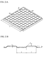
- Example 5 uses a panel 1E shown in FIG. 5 and FIG. 6E , and the arrangement and dimensions of protrusions and recesses of the analysis model are shown in FIG. 18 . Moreover, it is shown as No. 9 in the analysis result graphs ( FIG. 19 and FIG. 20 ).
- the distance between the centers of adjacent protrusions 4E is 30 mm, that is to say, the length of each edge of the quadrangular frustrum bottom surface of each planarly regular-quadrangular-shaped protrusion 4E is 30 mm, the length of each edge of the quadrangular frustrum top surface thereof is 27 mm, the length of each edge of the quadrangular frustrum bottom surface of each recess 6E is 30 mm, and the length of each edge of the quadrangular frustrum top surface thereof is 27 mm. Furthermore, the protrusion dimension of each protrusion 4E from the flat surface section 2 is 1.5 mm, and the recess dimension of each recess 6E from the flat surface section 2 is 1.5 mm.
- each protrusion 4E and the quadrangular frustrum top surface of each recess 6E is 3 mm
- the inclination angle of the inclined surface section 42E of the protrusion 4E and the inclination angle of the inclined surface section 62E of the recess 6E with respect to the reference surface F are respectively 45°.
- the chamfer dimensions of the protrusion 4E and the recess 6E are respectively 1.5 mm, that is to say, the length of the respective diagonal lengths of each top flat section 5E of the regular quadrangular shape are 3 mm, and the inclination angles of the corner section inclined surface 43E and the corner section inclined surface 63E with respect to the reference surface F are respectively 45°.
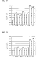
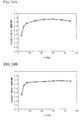
- FIG. 19 and FIG. 20 show FEM analysis results.
- FIG. 19 is a graph showing rigidity ratios in the bending model in which there are shown values found by dividing vertical displacement of the panel center in the panel 10A of Comparative Example 1 by vertical displacement of the panel center in the panels 1 and 10 of the respective examples and comparative examples.
- FIG. 20 is a graph showing rigidity ratios in the torsion model in which there are shown values found by dividing vertical displacement of the load application position in the panel 10A of Comparative Example 1 by vertical displacement of the load application position in the panels 1 and 10 of the respective examples and comparative examples. That is to say, FIG. 19 and FIG.
- FIG. 19 and FIG. 20 show the ratio of increments in bending rigidity and torsional rigidity of the panels 1A to 1E of Examples 1 to 5 and the panels 10B to 10D of Comparative Examples 2 to 4, with respect to the panel 10A of Comparative Example 1, which has no protrusion and recess.
- the vertical axis in FIG. 19 and FIG. 20 each represents rigidity ratio.
- the bending rigidity of the panels 10B to 10D of Comparative Examples 2 to 4 (No. 2, 3, and 4) increased by only 1.9 times to 2.32 times
- the bending rigidity of the panels 1A to 1C of Examples 1 to 3 (No. 5 to 7) increased by only 2.35 times to 2.75 times
- the bending rigidity of the panels 1D and 1E of Examples 4 and 5 (No. 8 and 9) increased by 3.98 times and 3.74 times, that is, nearly four times that of the panel 10A of Comparative Example 1.
- the level of bending rigidity increases to a level similar to or higher than that of the conventional panels 10B and 10C having protrusions and recesses (Comparative Examples 2 and 3). Furthermore, it has been learned that in the panels 1D and 1E of Examples 4 and 5 according to the embodiments of the present invention, the level of bending rigidity increases by approximately 1.6 to 1.9 times compared to the conventional panels 10B and 10C.
- the torsional rigidity of the panels 10B to 10D of Comparative Examples 2 to 4 (No. 2, 3, and 4) increased by only 1.18 times to 1.58 times
- the torsional rigidity of the panels 1A to 1C of Examples 1 to 3 (No. 5 to 7) increased by only 1.49 times to 1.56 times
- the torsional rigidity of the panels 1D and 1E of Examples 4 and 5 (No. 8 and 9) increased by 3.26 times and 3.34 times, that is, more than three times that of the panel 10A of Comparative Example 1.
- the level of torsional rigidity increases to a level similar to that of the conventional panels 10B and 10C having protrusions and recesses (Comparative Examples 2 and 3). Furthermore, it has been learned that in the panels 1D and 1E of Examples 4 and 5 according to the embodiments of the present invention, the level of torsional rigidity increases by approximately 2.1 to 2.2 times compared to the conventional panels 10B and 10C.
- the dimensions of the respective sections of the panel 1 shown in the above examples are merely an example, and they may be appropriately changed according to the intended purpose. An effect in the case of further changing the dimension of the respective sections of the panel 1 from those in the above example is described based on FIG. 21A to FIG. 27B and Tables 1 to 10.
- the dimensions of the respective sections of the panel 1 are denoted by symbols shown in FIG. 21A to FIG. 23B .
- FIG. 22D respectively illustrate: the distance H between the quadrangular frustrum top surface of the protrusion and the quadrangular frustrum top surface of the recess; the plate thickness t; the length J of each edge of the quadrangular frustrum bottom surface of the protrusion and the recess; the inclination angle ⁇ of the inclined surfaces of the protrusion and the recess with respect to the reference surface F; the number m of the protrusions and the recesses; and the panel size L and the panel size L' excluding the flat surface section of the panel periphery.
- the dimensions of the respective sections in FIG. 23A and FIG. 23B respectively illustrate the length J of each edge of the quadrangular frustrum bottom surface, and the diagonal length K of the top flat section.
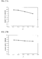
- Example 4 Taking the panel shape of Example 4 as a base, respective rigidity ratios of bending rigidity and torsional rigidity in the case of changing the inclination angle ⁇ with use of the dimensions of the respective sections of the panel shown in Tables 1 and 2 (as with Comparative Example 1, a panel having no protrusions and recesses is taken as the reference of comparison) are shown in FIG. 24A and FIG. 24B .
- Tables 1 and 2 each show bending rigidity ratio (Table 1) and torsional rigidity ratio (Table 2) in the case of changing the inclination angle ⁇ of the protrusions and the recesses.
- Example 4 Taking the panel shape of Example 4 as a base, respective rigidity ratios of bending rigidity and torsional rigidity in the case of changing the distance H between the top surface of the quadrangular frustrum of the protrusion and the top surface of the quadrangular frustrum of the recess with use of the dimensions of the respective sections of the panel shown in Tables 3 to 8 (a panel having no protrusions and recesses is taken as the reference of comparison) are shown in FIG. 25 .
- Example 5 Taking the panel shape of Example 5 as a base, respective rigidity ratios of bending rigidity and torsional rigidity in the case of changing the diagonal length K of the top flat section with use of the dimensions of the respective sections of the panel shown in Tables 9 and 10 (a panel having no protrusions and recesses is taken as the reference of comparison) are shown in FIG. 26A and FIG. 26B .
- Tables 9 and 10 each show bending rigidity ratio (Table 9) and torsional rigidity ratio (Table 10) in the case of changing the diagonal length K of the top flat section.
- Example 4 Taking the panel shape of Example 4 as a base, respective rigidity ratios of bending rigidity and torsional rigidity in the case of changing the ratio of the length J of each edge of the quadrangular frustrum bottom surface of the protrusion and recess with respect to the panel size L (corresponding to the inverse number of the number m of protrusions and recesses) with use of the dimensions of the respective sections of the panel shown in Tables 11 and 12 (a panel having no protrusions and recesses is taken as the reference of comparison), are shown in FIG. 27A and FIG. 28B.
- Table 11 shows bending rigidity ratios
- Table 12 shows torsional rigidity ratios.
- J / L 0.5
- a checkered pattern which is formed with a combination of a minimum number of protrusions and recesses including two protrusions and two recesses. That is to say, as a special form of configuration of protrusions and recesses, other than the configuration in which protrusions and recesses alternately surround four edges, there may be provided a configuration such that two edges among the peripheral edges of the protrusion and the recess are surrounded by flat sections, the surfaces of which are different from the top surface of the quadrangular frustrum.
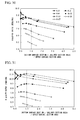
- Example 5 Taking the panel shape of Example 5 as a base, respective rigidity ratios of bending rigidity and torsional rigidity in the case of changing the diagonal length K of the top flat section 5E and the inclination angle ⁇ of the inclined surface section 42E (62E) (a panel having no protrusions and recesses is taken as the reference of comparison), are shown in FIGS. 28, 29 , 30, and 31 .
- the inclination angle ⁇ of the inclined surface section 42E (62E) takes values shown in Tables 13 to 40.
- FIG. 28 (H 3, bending) and FIG.
- each horizontal axis represents the value found by dividing the sum of the area S3 of the top flat section 5E and the area S4 of the inclined section (sum of the inclined surface section 42E (62E) and the corner section inclined surface 43 E) by the sum of the area S 1 of the upper surface section 41E and the area S2 of the bottom surface section 61E, and each vertical axis represents each rigidity ratio of bending rigidity and torsional rigidity.
- the area S1 of the upper surface section 41E, the area S2 of the bottom surface section 61E, and the area S3 of the top flat section 5E are surface areas
- the area S4 of the inclined section (sum of the inclined surface section 42E (62E) and the corner section inclined surface 43E) is a projected area projected on the reference surface F when the inclined surface section 42E (62E) and the corner section inclined surface 43E are projected from the upper surface.
- rigidity ratio changes with values of the diagonal length K of the top flat section 5E and the inclination angle ⁇ of the inclined surface section 42E (62E).
- values of the optimum diagonal length K and the inclination angle ⁇ can be found in design, suitable values for K and ⁇ may change due to the characteristics of materials to be used for the panel, and also they may be changed in order to ensure secondary-workability when forming the shape of the panel with protrusions and recesses provided thereon.
- the present invention is not a configuration to be limited by the above embodiments, and includes other configurations which enable realization of the object of the present invention.
- the present invention also includes modifications such as those shown below.
- the reference surface F of the panel 1 is a flat surface.
- the reference surface F is not limited to a flat surface, and it may be a cylindrical surface, a spherical surface, a gently curved surface, or any other three-dimensional curved surface.
- the shape of the panel 1 is not limited to a rectangular shape, and a panel in an arbitrary shape may be used.
- the shapes of the flat surface of the protrusions, the recesses, and the flat sections are not limited to those in the above embodiments, and an arbitrary shape may be used.
- the protrusions and the recesses do not always have to be formed only with protrusions from the reference surface to one side and with recesses to the other side, and it is possible, only with protrusions to one side or only with recesses to the other side, to obtain a panel having an arrangement and dimensions of protrusions and recesses of the intended purpose as a result.
- the distance H between the quadrangular frustrum top surfaces of the protrusion and the recess does not always have to be greater than the plate thickness, and the panel may be provided with H smaller than the plate thickness t.
- the plate bending radius for forming protrusions and recesses may be appropriately set according to the characteristics of the material to be used for the panel.
- the present invention is not limited to these. That is to say, although the present invention is especially illustrated and described primarily for the specific embodiments, those working in the field may make various modifications to the above embodiments in terms of shape, material, quantity, and other detailed configurations, without departing from the technical idea and the scope of the invention. Therefore, the description which limits the shapes and materials disclosed above refers to panels illustrated as examples for facilitating understanding of the present invention, and the present invention is not limited by these shapes and materials. Therefore, the present invention includes descriptions made with names of members which do not have part or all of the limitations on these shapes and materials.
- a panel which has a simple structure and is capable of reliably increasing the level of rigidity thereof and reducing the weight thereof.
Landscapes
- Engineering & Computer Science (AREA)
- Architecture (AREA)
- Civil Engineering (AREA)
- Structural Engineering (AREA)
- Finishing Walls (AREA)
- Shaping Metal By Deep-Drawing, Or The Like (AREA)
- Panels For Use In Building Construction (AREA)
- Exhaust Silencers (AREA)
- Moulds For Moulding Plastics Or The Like (AREA)
Applications Claiming Priority (2)
| Application Number | Priority Date | Filing Date | Title |
|---|---|---|---|
| JP2010004858 | 2010-01-13 | ||
| PCT/JP2011/050423 WO2011087047A1 (fr) | 2010-01-13 | 2011-01-13 | Panneau |
Publications (2)
| Publication Number | Publication Date |
|---|---|
| EP2525009A1 true EP2525009A1 (fr) | 2012-11-21 |
| EP2525009A4 EP2525009A4 (fr) | 2013-07-03 |
Family
ID=44266201
Family Applications (1)
| Application Number | Title | Priority Date | Filing Date |
|---|---|---|---|
| EP11732917.7A Withdrawn EP2525009A4 (fr) | 2010-01-13 | 2011-01-13 | Panneau |
Country Status (12)
| Country | Link |
|---|---|
| US (1) | US8932700B2 (fr) |
| EP (1) | EP2525009A4 (fr) |
| JP (2) | JP4932968B2 (fr) |
| KR (1) | KR101284480B1 (fr) |
| CN (2) | CN102127947B (fr) |
| AU (1) | AU2011206085B2 (fr) |
| BR (1) | BR112012016859A2 (fr) |
| CA (1) | CA2786795C (fr) |
| MX (1) | MX2012008095A (fr) |
| MY (1) | MY161274A (fr) |
| TW (2) | TW201333359A (fr) |
| WO (1) | WO2011087047A1 (fr) |
Families Citing this family (23)
| Publication number | Priority date | Publication date | Assignee | Title |
|---|---|---|---|---|
| JP4932968B2 (ja) * | 2010-01-13 | 2012-05-16 | 新日本製鐵株式会社 | パネル |
| US9091049B2 (en) * | 2010-08-24 | 2015-07-28 | James Walker | Ventilated structural panels and method of construction with ventilated structural panels |
| US9604428B2 (en) | 2010-08-24 | 2017-03-28 | James Walker | Ventilated structural panels and method of construction with ventilated structural panels |
| US9090288B2 (en) * | 2010-09-08 | 2015-07-28 | Sumitomo Light Metal Industries, Ltd. | Sheet material having a concave-convex part, and vehicle panel and laminated structure using the same |
| JP5212583B1 (ja) * | 2011-07-20 | 2013-06-19 | 新日鐵住金株式会社 | パネル |
| JP2015028557A (ja) * | 2013-07-30 | 2015-02-12 | シャープ株式会社 | 表示装置、及びテレビ受信装置 |
| JP5754828B1 (ja) * | 2013-09-18 | 2015-07-29 | 日立機材株式会社 | 蓋部材及びこれを用いたフロアパネル |
| MX2016006868A (es) | 2013-11-26 | 2016-08-17 | Nippon Steel & Sumitomo Metal Corp | Panel que tiene rebajes y protuberancias. |
| WO2015137482A1 (fr) | 2014-03-14 | 2015-09-17 | 新日鐵住金株式会社 | Panneau |
| MX382550B (es) * | 2014-10-21 | 2025-03-13 | Creative Plastic Concepts Llc | Tapa para recipiente con caracteristicas en la superficie y puentes de conexion. |
| EP3434501A4 (fr) * | 2016-03-23 | 2019-11-27 | Nippon Steel Corporation | Panneau interne de porte et procédé de fabrication de panneau interne de porte |
| US10286958B2 (en) | 2017-07-14 | 2019-05-14 | Toyota Motor Engineering & Manufacturing North America, Inc. | Vehicles including mesh stamped panels |
| US11365542B2 (en) * | 2018-01-10 | 2022-06-21 | Shuert Technology, Llc | Plastic core structure manufactured through twin sheet technology |
| JP7145483B2 (ja) * | 2018-06-26 | 2022-10-03 | 学校法人大同学園 | 構造部材および骨組構造 |
| JP2020139270A (ja) * | 2019-02-26 | 2020-09-03 | 日本製鉄株式会社 | 耐力壁及び壁面材 |
| JP7467040B2 (ja) * | 2019-07-05 | 2024-04-15 | 三菱重工業株式会社 | パネル構造体及びパネル構造体の製造方法 |
| CN111591433B (zh) * | 2019-11-12 | 2021-10-22 | 中国科学院兰州化学物理研究所 | 一种柔性蒙皮及其制备方法和应用 |
| USD943781S1 (en) * | 2021-02-24 | 2022-02-15 | Shenzhen Lizhijia Industrial Co., Ltd | 3D wall panel |
| USD947417S1 (en) * | 2021-04-19 | 2022-03-29 | Shenzhen Lizhijia Industrial Co., Ltd | 3D wall panel |
| USD944420S1 (en) * | 2021-04-19 | 2022-02-22 | Shenzhen Lizhijia Industrial Co., Ltd | 3D wall panel |
| JP7795100B2 (ja) * | 2022-04-15 | 2026-01-07 | 日本製鉄株式会社 | ダッシュパネルおよび車体前部構造 |
| USD1066445S1 (en) | 2022-09-08 | 2025-03-11 | DuraPlas, LP | Equipment support pad |
| USD1052758S1 (en) * | 2023-01-19 | 2024-11-26 | STP North America LLC | Sound deadening panel for use in transportation units |
Family Cites Families (25)
| Publication number | Priority date | Publication date | Assignee | Title |
|---|---|---|---|---|
| US1000694A (en) | 1908-04-16 | 1911-08-15 | Frederic Schaefer | Removable egg-case partition. |
| US1154254A (en) * | 1909-11-05 | 1915-09-21 | Universal Electric Welding Co | Sheet-metal panel-work. |
| US2086857A (en) * | 1935-09-09 | 1937-07-13 | Norman L Derby | Method of making bimetallic elements |
| US2813652A (en) * | 1953-05-28 | 1957-11-19 | Keyes Fibre Co | Tray for fragile articles |
| US3558394A (en) * | 1969-05-19 | 1971-01-26 | Hans Jorg Marby | Method of making a three dimensional configured laminated article |
| DE3206163A1 (de) * | 1982-02-20 | 1983-09-01 | Helmut 7812 Bad Krozingen Keck | Bauelement |
| US4495237A (en) * | 1983-06-10 | 1985-01-22 | Patterson Fred R | Pyramidal core structure |
| JPS63187623U (fr) * | 1987-05-26 | 1988-12-01 | ||
| IT1265477B1 (it) | 1993-12-30 | 1996-11-22 | Dipiemme Dies And Plastic Mach | Pannello strutturale in plastica, procedimento e impianto di fabbricazione. |
| CA2144295C (fr) * | 1995-03-09 | 2005-05-24 | Germain Belanger | Panneau d'ame |
| JPH10166481A (ja) * | 1996-12-17 | 1998-06-23 | Hideo Yugawa | パネル芯材 |
| GB2341195B (en) * | 1998-07-15 | 2002-05-01 | Cyril Sloggett | Stiffened sheet and profiled ductile material |
| JP2960402B1 (ja) | 1998-07-17 | 1999-10-06 | 川崎重工業株式会社 | 軽量型高剛性パネル |
| DE10062341A1 (de) | 2000-12-14 | 2002-06-20 | Interplast Kunststoffe Gmbh | Verbundplatte, vorzugsweise aus Kunststoff und Verfahren zu deren Herstellung |
| TWI225531B (en) | 2002-09-04 | 2004-12-21 | Univ Brigham Young | Three-dimensional grid panel |
| DE10252207B3 (de) * | 2002-11-09 | 2004-02-26 | Bohmann, Dirk, Dr.-Ing. | Formteil als Kern eines Sandwichs |
| JP4707487B2 (ja) | 2005-07-19 | 2011-06-22 | 武敏 野島 | パネルおよびパネル作成方法 |
| WO2007010868A1 (fr) * | 2005-07-19 | 2007-01-25 | Kyoto University | Panneau, pièce de panneau et procédé de fabrication d’un panneau |
| JP4388558B2 (ja) | 2007-01-24 | 2009-12-24 | 株式会社深井製作所 | ヒートインシュレータ |
| JP4462327B2 (ja) * | 2007-10-26 | 2010-05-12 | 株式会社デンソー | 気筒特性ばらつき検出装置 |
| WO2009108712A2 (fr) | 2008-02-26 | 2009-09-03 | Klaus Stadthagen-Gonzalez | Elément structurel |
| DE202008008440U1 (de) * | 2008-06-24 | 2008-10-09 | Wischemann, Heinrich | Leichtbauplatte |
| JP2011027248A (ja) | 2009-07-01 | 2011-02-10 | Sumitomo Light Metal Ind Ltd | 凹凸部を有する板材及びその凹凸部形状の設計方法 |
| JP2011110847A (ja) * | 2009-11-27 | 2011-06-09 | Sumitomo Light Metal Ind Ltd | 凹凸部を有する板材並びにこれを用いた車両パネル及び積層構造体 |
| JP4932968B2 (ja) * | 2010-01-13 | 2012-05-16 | 新日本製鐵株式会社 | パネル |
-
2011
- 2011-01-13 JP JP2011527533A patent/JP4932968B2/ja active Active
- 2011-01-13 MX MX2012008095A patent/MX2012008095A/es active IP Right Grant
- 2011-01-13 EP EP11732917.7A patent/EP2525009A4/fr not_active Withdrawn
- 2011-01-13 TW TW102113995A patent/TW201333359A/zh unknown
- 2011-01-13 BR BR112012016859A patent/BR112012016859A2/pt not_active IP Right Cessation
- 2011-01-13 MY MYPI2012700444A patent/MY161274A/en unknown
- 2011-01-13 CN CN2011100071037A patent/CN102127947B/zh active Active
- 2011-01-13 US US13/521,714 patent/US8932700B2/en active Active
- 2011-01-13 WO PCT/JP2011/050423 patent/WO2011087047A1/fr not_active Ceased
- 2011-01-13 KR KR1020127017892A patent/KR101284480B1/ko active Active
- 2011-01-13 TW TW100101240A patent/TWI411740B/zh active
- 2011-01-13 CN CN2011200105344U patent/CN202090502U/zh not_active Expired - Lifetime
- 2011-01-13 AU AU2011206085A patent/AU2011206085B2/en active Active
- 2011-01-13 CA CA2786795A patent/CA2786795C/fr not_active Expired - Fee Related
- 2011-12-19 JP JP2011277309A patent/JP5218633B2/ja active Active
Also Published As
| Publication number | Publication date |
|---|---|
| TWI411740B (zh) | 2013-10-11 |
| CA2786795A1 (fr) | 2011-07-21 |
| AU2011206085B2 (en) | 2015-09-10 |
| KR20120098874A (ko) | 2012-09-05 |
| WO2011087047A1 (fr) | 2011-07-21 |
| TW201144648A (en) | 2011-12-16 |
| CN102127947A (zh) | 2011-07-20 |
| JP4932968B2 (ja) | 2012-05-16 |
| US8932700B2 (en) | 2015-01-13 |
| AU2011206085A1 (en) | 2012-08-02 |
| CN202090502U (zh) | 2011-12-28 |
| EP2525009A4 (fr) | 2013-07-03 |
| MX2012008095A (es) | 2012-07-30 |
| KR101284480B1 (ko) | 2013-07-16 |
| US20120295065A1 (en) | 2012-11-22 |
| CN102127947B (zh) | 2013-05-01 |
| JP2012067595A (ja) | 2012-04-05 |
| JP5218633B2 (ja) | 2013-06-26 |
| BR112012016859A2 (pt) | 2023-11-21 |
| TW201333359A (zh) | 2013-08-16 |
| MY161274A (en) | 2017-04-14 |
| CA2786795C (fr) | 2014-07-29 |
| JPWO2011087047A1 (ja) | 2013-05-20 |
Similar Documents
| Publication | Publication Date | Title |
|---|---|---|
| EP2525009A1 (fr) | Panneau | |
| US20130183498A1 (en) | Sheet material having a concave-convex part, and vehicle panel and laminated structure using the same | |
| EP2594347A1 (fr) | Plaque ayant une partie inégale et panneau de véhicule et structure stratifiée utilisant cette plaque | |
| CN105764781B (zh) | 具有凹凸的面板 | |
| US9017798B2 (en) | Press-formed product | |
| US20130295406A1 (en) | Sheet material having a concave-convex part, and vehicle panel and laminated structure using the same | |
| WO2011063447A1 (fr) | Élément structurel | |
| US20130288015A1 (en) | Sheet material having a concave-convex part, and a vehicle panel and laminated structure using the same | |
| US8920908B2 (en) | Sheet material having a concave-convex part, and vehicle panel and laminated structure using the same | |
| US9593492B2 (en) | Lid member and floor panel using the same | |
| CN110871852B (zh) | 帽型构件和帽型构件的制造方法 | |
| TWI417232B (zh) | 貨物用容器 | |
| JP7200167B2 (ja) | 車両用強度部材 | |
| CN207107501U (zh) | 集装箱波形板及具有其的集装箱 | |
| CN216469954U (zh) | 一种集装箱的顶板及具有其的集装箱 | |
| JP5203987B2 (ja) | 車両パネル構造体 | |
| JP2002127278A (ja) | 波形芯材サンドイッチパネル | |
| JP5532184B2 (ja) | フレーム構造体及び箱状構造体 | |
| JP5198215B2 (ja) | 鋼板製構造材 |
Legal Events
| Date | Code | Title | Description |
|---|---|---|---|
| PUAI | Public reference made under article 153(3) epc to a published international application that has entered the european phase |
Free format text: ORIGINAL CODE: 0009012 |
|
| 17P | Request for examination filed |
Effective date: 20120801 |
|
| AK | Designated contracting states |
Kind code of ref document: A1 Designated state(s): AL AT BE BG CH CY CZ DE DK EE ES FI FR GB GR HR HU IE IS IT LI LT LU LV MC MK MT NL NO PL PT RO RS SE SI SK SM TR |
|
| RAP1 | Party data changed (applicant data changed or rights of an application transferred) |
Owner name: NIPPON STEEL & SUMITOMO METAL CORPORATION |
|
| DAX | Request for extension of the european patent (deleted) | ||
| A4 | Supplementary search report drawn up and despatched |
Effective date: 20130604 |
|
| RIC1 | Information provided on ipc code assigned before grant |
Ipc: E04C 2/30 20060101AFI20130528BHEP |
|
| 17Q | First examination report despatched |
Effective date: 20150602 |
|
| RAP1 | Party data changed (applicant data changed or rights of an application transferred) |
Owner name: NIPPON STEEL CORPORATION |
|
| STAA | Information on the status of an ep patent application or granted ep patent |
Free format text: STATUS: THE APPLICATION IS DEEMED TO BE WITHDRAWN |
|
| 18D | Application deemed to be withdrawn |
Effective date: 20200617 |