EP2525023B1 - Dispositif de protection destiné à une serrure de porte - Google Patents
Dispositif de protection destiné à une serrure de porte Download PDFInfo
- Publication number
- EP2525023B1 EP2525023B1 EP12162097.5A EP12162097A EP2525023B1 EP 2525023 B1 EP2525023 B1 EP 2525023B1 EP 12162097 A EP12162097 A EP 12162097A EP 2525023 B1 EP2525023 B1 EP 2525023B1
- Authority
- EP
- European Patent Office
- Prior art keywords
- cams
- plate
- pins
- seats
- covering element
- Prior art date
- Legal status (The legal status is an assumption and is not a legal conclusion. Google has not performed a legal analysis and makes no representation as to the accuracy of the status listed.)
- Active
Links
Images




Classifications
-
- E—FIXED CONSTRUCTIONS
- E05—LOCKS; KEYS; WINDOW OR DOOR FITTINGS; SAFES
- E05B—LOCKS; ACCESSORIES THEREFOR; HANDCUFFS
- E05B37/00—Permutation or combination locks; Puzzle locks
- E05B37/12—Permutation or combination locks; Puzzle locks with tumbler discs on several axes
-
- E—FIXED CONSTRUCTIONS
- E05—LOCKS; KEYS; WINDOW OR DOOR FITTINGS; SAFES
- E05B—LOCKS; ACCESSORIES THEREFOR; HANDCUFFS
- E05B17/00—Accessories in connection with locks
- E05B17/14—Closures or guards for keyholes
- E05B17/145—Closures or guards for keyholes with combination lock
-
- E—FIXED CONSTRUCTIONS
- E05—LOCKS; KEYS; WINDOW OR DOOR FITTINGS; SAFES
- E05B—LOCKS; ACCESSORIES THEREFOR; HANDCUFFS
- E05B17/00—Accessories in connection with locks
- E05B17/14—Closures or guards for keyholes
- E05B17/18—Closures or guards for keyholes shaped as lids or slides
- E05B17/186—Closures or guards for keyholes shaped as lids or slides sliding
-
- E—FIXED CONSTRUCTIONS
- E05—LOCKS; KEYS; WINDOW OR DOOR FITTINGS; SAFES
- E05B—LOCKS; ACCESSORIES THEREFOR; HANDCUFFS
- E05B47/00—Operating or controlling locks or other fastening devices by electric or magnetic means
- E05B47/0038—Operating or controlling locks or other fastening devices by electric or magnetic means using permanent magnets
-
- E—FIXED CONSTRUCTIONS
- E05—LOCKS; KEYS; WINDOW OR DOOR FITTINGS; SAFES
- E05B—LOCKS; ACCESSORIES THEREFOR; HANDCUFFS
- E05B47/00—Operating or controlling locks or other fastening devices by electric or magnetic means
- E05B47/0038—Operating or controlling locks or other fastening devices by electric or magnetic means using permanent magnets
- E05B47/0045—Operating or controlling locks or other fastening devices by electric or magnetic means using permanent magnets keys with permanent magnets
-
- Y—GENERAL TAGGING OF NEW TECHNOLOGICAL DEVELOPMENTS; GENERAL TAGGING OF CROSS-SECTIONAL TECHNOLOGIES SPANNING OVER SEVERAL SECTIONS OF THE IPC; TECHNICAL SUBJECTS COVERED BY FORMER USPC CROSS-REFERENCE ART COLLECTIONS [XRACs] AND DIGESTS
- Y10—TECHNICAL SUBJECTS COVERED BY FORMER USPC
- Y10T—TECHNICAL SUBJECTS COVERED BY FORMER US CLASSIFICATION
- Y10T70/00—Locks
- Y10T70/70—Operating mechanism
- Y10T70/7051—Using a powered device [e.g., motor]
- Y10T70/7057—Permanent magnet
-
- Y—GENERAL TAGGING OF NEW TECHNOLOGICAL DEVELOPMENTS; GENERAL TAGGING OF CROSS-SECTIONAL TECHNOLOGIES SPANNING OVER SEVERAL SECTIONS OF THE IPC; TECHNICAL SUBJECTS COVERED BY FORMER USPC CROSS-REFERENCE ART COLLECTIONS [XRACs] AND DIGESTS
- Y10—TECHNICAL SUBJECTS COVERED BY FORMER USPC
- Y10T—TECHNICAL SUBJECTS COVERED BY FORMER US CLASSIFICATION
- Y10T70/00—Locks
- Y10T70/70—Operating mechanism
- Y10T70/7441—Key
- Y10T70/778—Operating elements
- Y10T70/7791—Keys
- Y10T70/7904—Magnetic features
-
- Y—GENERAL TAGGING OF NEW TECHNOLOGICAL DEVELOPMENTS; GENERAL TAGGING OF CROSS-SECTIONAL TECHNOLOGIES SPANNING OVER SEVERAL SECTIONS OF THE IPC; TECHNICAL SUBJECTS COVERED BY FORMER USPC CROSS-REFERENCE ART COLLECTIONS [XRACs] AND DIGESTS
- Y10—TECHNICAL SUBJECTS COVERED BY FORMER USPC
- Y10T—TECHNICAL SUBJECTS COVERED BY FORMER US CLASSIFICATION
- Y10T70/00—Locks
- Y10T70/70—Operating mechanism
- Y10T70/7441—Key
- Y10T70/7915—Tampering prevention or attack defeating
-
- Y—GENERAL TAGGING OF NEW TECHNOLOGICAL DEVELOPMENTS; GENERAL TAGGING OF CROSS-SECTIONAL TECHNOLOGIES SPANNING OVER SEVERAL SECTIONS OF THE IPC; TECHNICAL SUBJECTS COVERED BY FORMER USPC CROSS-REFERENCE ART COLLECTIONS [XRACs] AND DIGESTS
- Y10—TECHNICAL SUBJECTS COVERED BY FORMER USPC
- Y10T—TECHNICAL SUBJECTS COVERED BY FORMER US CLASSIFICATION
- Y10T70/00—Locks
- Y10T70/70—Operating mechanism
- Y10T70/7441—Key
- Y10T70/7915—Tampering prevention or attack defeating
- Y10T70/7921—Armoring
-
- Y—GENERAL TAGGING OF NEW TECHNOLOGICAL DEVELOPMENTS; GENERAL TAGGING OF CROSS-SECTIONAL TECHNOLOGIES SPANNING OVER SEVERAL SECTIONS OF THE IPC; TECHNICAL SUBJECTS COVERED BY FORMER USPC CROSS-REFERENCE ART COLLECTIONS [XRACs] AND DIGESTS
- Y10—TECHNICAL SUBJECTS COVERED BY FORMER USPC
- Y10T—TECHNICAL SUBJECTS COVERED BY FORMER US CLASSIFICATION
- Y10T70/00—Locks
- Y10T70/70—Operating mechanism
- Y10T70/7441—Key
- Y10T70/7915—Tampering prevention or attack defeating
- Y10T70/7955—Keyhole guards
- Y10T70/7977—Key-controlled
-
- Y—GENERAL TAGGING OF NEW TECHNOLOGICAL DEVELOPMENTS; GENERAL TAGGING OF CROSS-SECTIONAL TECHNOLOGIES SPANNING OVER SEVERAL SECTIONS OF THE IPC; TECHNICAL SUBJECTS COVERED BY FORMER USPC CROSS-REFERENCE ART COLLECTIONS [XRACs] AND DIGESTS
- Y10—TECHNICAL SUBJECTS COVERED BY FORMER USPC
- Y10T—TECHNICAL SUBJECTS COVERED BY FORMER US CLASSIFICATION
- Y10T70/00—Locks
- Y10T70/80—Parts, attachments, accessories and adjuncts
- Y10T70/8432—For key-operated mechanism
- Y10T70/8649—Keyhole covers
Definitions
- the present invention relates to a protective device, particularly for a lock of a door or leaf, for example a door for access to a home, or a gate, or a door of a safe cabinet.
- locks which are adapted for example to allow the closure and re-opening of a door or gate and comprise a preset cylinder which can be actuated by means of a suitable key which can be inserted in a keyhole provided axially to this cylinder.
- cylinders of the known type are typically made of brass and therefore do not have a high mechanical strength, being thus easy to break into by drilling and/or breaking and/or stripping.
- an adapted covering element which is constituted by a stud which has a substantially circular plan shape and has, at the keyhole of the cylinder, a circular hole inside which a keyhole protection disk, in which there is a slot adapted to allow the insertion of the key, is rotatably accommodated.
- the stud constitutes therefore a protection for the cylinder and allows at the same time the insertion and rotation of the key in the keyhole thereof.
- patent application no. TV2003A000115 of August 7, 2003 which describes a protective device for the cylinder of a lock which comprises a plate, with an approximately rectangular plan shape, which can be fixed to a door so as to cover the lock, and can be provided, proximate to one end, with a suitable opening for access to the cylinder of said lock.
- adapted seats On the front surface of the plate, which is directed opposite to the lock, there are two adapted seats having a circular plan shape within which two substantially cylindrical cams are accommodated so that they can rotate, two recesses with semicircular profiles being formed radially on their lateral surfaces; adapted first magnets are inserted within said cams.
- Two through ducts are provided on the lateral surface of these seats, along two axes which are transverse to the plate, and suitable lock pins are accommodated so that they can slide within said ducts, said pins having such dimensions as to be able to be partially inserted in the recesses formed in the cams; these pins are pushed toward the outside of the respective ducts, so as to exit transversely from the lateral surfaces of the plate, by the action of adapted springs inserted in said ducts.
- a covering element is associated slidingly with the plate and can slide longitudinally thereto, so as to conceal selectively, with one of its ends, the opening for access to the lock.
- This covering element is shaped, in an approximately C-shaped transverse cross-section, so as to define a substantially rectangular base arranged, when in use, so as to face the front surface of the plate; two arms protrude from the longitudinal ends of said base, envelop the lateral surfaces of the plate and are coupled slidingly thereto.
- Two adapted slots are formed on the surface of said arms that is directed toward the longitudinal surfaces of the plate; in the condition in which the covering element conceals completely the opening for accessing the lock, the pins that protrude transversely from the lateral surfaces of the plate are inserted in said slots so as to block the mutual sliding between the plate and the covering element.
- the release of the covering element is obtained by arranging in a complementarily shaped groove formed on the base thereof an adapted magnetic key which contains preset second magnets adapted to mate with the first magnets provided in the cams, so as to cause the rotation of said cams to the condition in which the recesses formed in them face the channels that contain the pins.
- a traction of the covering element in the direction of its spacing from the opening for accessing the lock causes the exit of the pins from the cavities formed in the arms of said covering element and the simultaneous partial insertion of said pins in the recesses of the cams; in this manner, the sliding of the covering element with respect to the plate is freed, thus allowing access to the lock.
- the mutual interaction between the first magnets of the two cams causes a rotation thereof such as to break up the alignment of the recesses with respect to the ducts that contain the pins; the covering element is therefore again locked in a closed condition.
- Italian patent no. 01288200 is also known which describes a safety device for the protection of the external side of a system for closing doors or door-frames for entry, which comprises a fixed base element, which is arranged and shaped to surround a locking cylinder, i.e., the hole for the key of the closing system.
- a longitudinal seat Frontally to the base element there is a longitudinal seat, with two parallel sides in which a movable body is accommodated so that it can slide; said body can be moved between an active position, in which said movable body is arranged in front of the cylinder, i.e., of the locking hole, concealing it, and a passive position, in which said movable body is spaced from the cylinder, i.e., from the locking hole, so as to allow access thereto.
- the device comprises, moreover, a combination system in order to lock/unlock the movable body in the active position, constituted by rotating coded knobs which are mounted on the movable body, each one carrying a lock/unlock disk, arranged on the inner face of the movable body, between the sides of the front seat of the base element; on these sides, for each one of the disks, there is a recess which is partially shaped complementary, in plan view, to the respective disk and is arranged so that when the movable body is in the active position each disk is arranged proximate to one of said recesses.
- the disks moreover, have a lateral flattened portion, which can be arranged selectively, following the rotation of the disk, at the respective recess or not; with the movable body in the active position, when the flattened portion of a disk is not at the recess, said disk protrudes transversely from the movable body with its curved part, which is thus arranged inside the adjacent recess, preventing the sliding of the movable body with respect to the base element and thus keeping said movable body in the active position.
- the coded knobs By rotating in a suitable manner the coded knobs it is possible to rotate the disks until the flattened portion that is present in all of them is at the respective recess; in this condition, the disks do not protrude transversely from the movable body, which is no longer coupled to the base element and can therefore be induced to slide to the passive position.
- the release of the movable body is therefore possible only by knowing the correct combination that makes it possible to rotate conveniently the coded knobs and the lock/unlock disks with them.
- the position of the coded knobs that makes it possible to achieve the release of the movable body is not defined unequivocally, because in order to achieve the release of the movable body it is sufficient that all the disks are arranged so that their flattened portion is partially contained in the recess and directed away from the locking cylinder or hole for the key of the closing system; in fact in this condition, which can be achieved with the coded knobs in various positions, by pulling the movable body in the opening direction the flattened portion of the various disks abuts against the edge of the respective recess, causing the rotation of the respective disk up to the condition in which the curved portion thereof protrudes completely from the recess, thus releasing the sliding of the movable body.
- this device of the known type has a further drawback: as also observed previously, when the movable body is in the passive position the coded knobs are arranged necessarily so as to define the opening combination; in order to prevent someone from being able to read this combination in this condition it is therefore necessary, after each use, to return the movable body to the passive condition and rotate the coded knobs in order to achieve the locking of said movable body, and this may be inconvenient.
- a protective device particularly for a lock of a door or leaf, which comprises a covering element associated slidingly with a plate which can be fixed to said door or leaf and can be arranged selectively so as to close an opening, for accessing said lock, which is formed in said plate, at least two pins being associated transversely with said plate and cooperating with cams associated rotatably within said plate and adapted to block temporarily the sliding of said covering element with respect to said plate, characterized in that said cams interact with a magnet-based combination element adapted to modify the angular position of said cams in order to allow or prevent the temporary mutual release of said pins and said covering element.
- the aim of the present invention is therefore to solve the described technical problems, eliminating the drawbacks of the cited background art and therefore devising an invention that allows an effective protection of the access to a lock, thus preventing attempts to tamper with it.
- an important object is to provide an invention that makes it possible to prevent a thief from reaching a condition of access to the lock after listening to the protective device with which it is associated.
- Another object of the invention is to make access to the lock extremely difficult even for an expert picker.
- Yet another object is to provide an invention that can be applied also to common locks of the known type.
- Another object is to provide an invention that is structurally simple and has relatively low manufacturing costs.
- a protective device 1 particularly for a lock of a door or leaf, comprising a covering element 9 which is associated slidingly with a plate 2 which can be fixed to said door or leaf and can be positioned selectively so as to close an opening 3, for access to said lock, which is provided in said plate 2, two pins 8a, 8b being associated transversely with said plate and being adapted to block temporarily the sliding of said covering element 9 with respect to said plate 2, characterized in that said pins 8a, 8b interact with the arms of a rotor 19, which is associated rotatably, in contrast with at least one elastically deformable means, within a cavity 5 provided in said plate 2, pivots protruding from said rotor 19 and cooperating selectively with at least three cams, which are freely associated so that they can rotate adjacent or proximate to a surface of said cavity 5, said at least three cams having an axis that lies at the vertices of a polygon and interacting with a
- the reference numeral 1 designates a protective device, particularly for a lock, not shown in the accompanying figures, of a door or leaf, such as, for example, the door for access to a home, a gate, the door of a safe cabinet, the door of a safe.
- the device 1 comprises a plate 2, which can be fixed to the door or leaf in such a position as to cover its lock, not shown in the accompanying figures.
- an adapted access opening 3 which is arranged, when in use, frontally to the lock, so as to allow access to it and the insertion of a key therein.
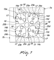
- first seats In the lower region of the plate 2 there are at least three first seats, preferably four and designated by the numerals 4a, 4b, 4c, 4d, which have a substantially circular plan shape and are arranged with their center at the corners of a polygon constituted, in the particular embodiment, by a square.
- the number of seats might also be higher than four and with the center at a polygon that has an equal number of sides; thus, if the seats are five the polygon will be a pentagon and so forth.
- a cavity 5 whose dimensions are at least equal to the projection of said four first seats 4a, 4b, 4c, 4d on the rear wall 6 of the plate 2.
- Said pins 8a, 8b are longer than the thickness of the side walls 7a, 7b and are designed to block temporarily, when they protrude beyond said side walls 7a, 7b with one end, the sliding of a covering element 9 which is associated slidingly and frontally with said plate 2 so as to block temporarily access to the access opening 3.
- an opening 11 which acts as seat for the arrangement of a magnetic key 12; said opening 11 is arranged so that in the condition in which the covering element 9 blocks the access opening 3 it lies in front of the four first seats 4a, 4b, 4c, 4d.
- At least three cams preferably four and designated by the numerals 13a, 13b, 13c, 13d, can be positioned at said seats so that they can rotate freely and are kept in position by means of adapted axes or pivots 14a, 14b, 14c, 14d, which are supported by adapted disks 15a, 15b, 15c, 15d which are arranged so as to close the four first seats 4a, 4b, 4c, 4d so as to avoid also the escape of said cams from said first seats.
- Each one of said cams 13a, 13b, 13c, 13d is substantially cylindrical and on the lateral surface of at least one of them there is, along a generatrix, at least one first recess 16, which is preferably but not necessarily approximately semicircular in plan view; advantageously, one or more first magnets 17 are associated with each one of said cams 13a, 13b, 13c, 13d.
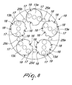
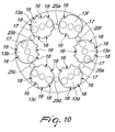
- each one of said cams 13a, 13b, 13c, 13d there is, moreover, as shown in Figures 8 to 11 , at least one additional second recess 18, which differs from the first recess 16 in that it has a semicircular plan shape with a smaller diameter.
- a rotor 19 can be positioned rotatably within the cavity 5 and is composed of a disk-shaped back 20, from which a protrusion 21 having a star-like plan shape protrudes which has, in the particular embodiment, an X-like shape with four arms 22a, 22b, 22c, 22d which are identical and mutually equidistant.
- the thickness of the back 20 and the size of the four arms 22a, 22b, 22c, 22d are such that the arms 22a, 22c interact with the pins 8a, 8b.
- the thickness of the back 20, moreover, is such that it arranges itself approximately adjacent to the surfaces of said facing cams 13a, 13b, 13c, 13d.
- the rotation of the rotor 19 occurs in contrast with at least one elastically deformable means constituted, in the particular embodiment, by two pistons 23a, 23b, which advantageously have an approximately hemispherical head and can slide axially, in contrast with a pair of springs 24a, 24b, within adapted seats provided in the side walls 7a, 7b along a same axis respectively of said pins 8a, 8b.
- At least four pivots 25a, 25b, 25c, 25d and a central pivot 26 protrude from the vertices of said arms 22a, 22b, 22c, 22d; said central pivot 26 is arranged in a central region with respect to said cams 13a, 13b, 13c, 13d and acts as a fulcrum for the rotation of the rotor 19.
- Each one of the four pivots 25a, 25b, 25c, 25d has such dimensions as to be able to arrange itself at one of said first recesses 16 or second recesses 18 provided in each one of said cams 13a, 13b, 13c, 13d; in the first case the rotation of said cams is prevented, and in the second case there is still a play that makes it possible to impose a rotation on the cams.
- the shape, and therefore for example the diameter, and the depth of the second recesses 18 are in fact such as to allow the temporary interaction of the pivots 25a, 25b, 25c, 25d (which enter them) therewith, but are also such as to allow the cams to rotate further and to maintain the condition of temporary locking of the sliding of said covering element 9.
- first and second recesses 16, 18 moreover affect preferably the entire thickness of the corresponding cam on which they are formed.
- the arrangement of the second recesses 18, may, with respect to the first recesses 16, be alternated or arranged according to a desired sequence; their number may be moreover very disparate according to the specific requirements, as well as their dimensions and their arrangement on each cam.
- Said second recesses 18 thus define false positions for the pivots 25a, 25b, 25c, 25d in their arrangement at the cams 13a, 13b, 13c, 13d, making listening and therefore tampering by a thief very difficult to achieve, because of the combination of false positions that can be reached by varying the number of the second recesses 18.
- the pair of springs 24a, 24b has such an elastic constant as to slightly force the rotor 19 to maintain the stalled position, shown in Figure 4 , in which none of the four pivots 25a, 25b, 25c, 25d affects any of the first recesses 16.
- a slight rotation imparted clockwise to the rotor 19 forces the first pivots 25a, 25c to arrange themselves adjacent to the lateral surface of the cams 13a, 13b, 13c, 13d; when a rotation is imposed on said cams (as described hereinafter) that arranges the first recesses 16 in front of the first pivots 25a, 25c, they arrange themselves within the first recesses 16, allowing a further rotation to the rotor 19, thanks to the additional movement imparted to the pins 8a, 8b by an extent that is sufficient to make them retract within the side walls 7a, 7b of the plate 2, so that the covering element 9 also can slide with respect to the plate 2, freeing the access to the access opening 3 and therefore the access to the lock.
- the sliding of the covering element 9 is allowed by the use of the magnetic key 12, which is arranged at the opening 11: the key imposes to the cams 13a, 13b, 13c, 13d such a rotation as to place the first recesses 16 of the cams 13a, 13b, 13c, 13d in such a position as to face the first pivots 25a, 25b, 25c, 25d, thus freeing the movement of the pins 8a, 8b.
- the device 1 also comprises upper and lower stroke limiting means of the known type, which are adapted to limit the sliding of the covering element 9 longitudinally to the plate 2, so as to prevent the complete exit of said plate 2 from said covering element 9.
- the cams 13a, 13b, 13c, 13d arrange themselves randomly inside the four first seats 4a, 4b, 4c, 4d; the pistons 23a, 23b thus force the pins 8a, 8b outside the side walls 7a, 7b, which thus block the covering element 9.
- This solution makes it possible to prevent a thief from reaching a condition of access to the lock after listening to the protective device with which it is associated, thanks to the presence of the second recesses 18 that define false positions for the pivots 25a, 25b, 25c, 25d in their arrangement at the cams 13a, 13b, 13c, 13d; therefore, if an ill-intentioned person tries to listen to the sound of the positioning of the pivots 25a, 25b, 25c, 25d in the cams 13a, 13b, 13c, 13d he will hear the sound of the arrangement of the pivots, but he will not be able to know whether they have been positioned in the first recesses 16, the only condition that makes it possible to achieve opening.
- the device according to the invention can be applied easily also to common locks of the known type.
- the production costs of the device according to the invention are kept low, since it is provided only by means of components that are easy to produce and/or assemble.
- the protective device according to the invention may be used to protect and allow selectively access for example to a switch, to an actuator and, in general, to any element that can be accessed selectively.
- the number of the first seats may be larger than four, and likewise the number of the cams may increase and may be even five or six or more, as shown in Figures 8 to 12 , and designated by the numerals 13a, 13b, 13c, 13d, 13e, 13f.
- the rotor 19 also will have a protrusion with a star-like plan shape with more than four arms, even five or six, as shown in Figures 8 to 12 .
- the number of the pivots accordingly also might be five or six or more, as shown in Figures 8 to 12 , and designated by the reference numerals 25a, 25b, 25c, 25d, 25e, 25f.
- Said pivots will lie on the vertices of a pentagon or a hexagon or other polygon with more sides.
- the key 12 will be such as to arrange, once it has been moved closer to the opening 11, the cams 13a, 13b, 13c, 13d, 13e, 13f in the position facing the first recesses 16.
- the number of second recesses 18 also can increase so as to increase the number of false positions of the pivots 25a, 25b, 25c, 25d, 25e, 25f which, arranged therein for example by a thief who might operate with an external magnet on the cams 13a, 13b, 13c, 13d, 13e, 13f, will not allow the sliding of the covering element 9 and therefore will not uncover the lock.
- the shape of the second recesses 18 also may vary according to the means that interfere with them.
- the positions of the pins 8a, 8b and of the pistons 23a, 23b also may be exchanged, meaning that the pin 8b will take the place of the piston 23a, consequently redefining the respective seats at the side walls 7a, 7b of the plate 2; likewise, the pin 8a will take the place of the piston 23b, the respective seats at the side walls 7a, 7b of the plate 2 being consequently redefined.
- cams 13a, 13b, 13c, 13d, 13e, 13f also may be the most suitable according to specific requirements.
- the shape of the rotor may be the most suitable for example according to the number and position of said cams 13a, 13b, 13c, 13d, 13e, 13f.
Landscapes
- Lock And Its Accessories (AREA)
- Casings For Electric Apparatus (AREA)
Claims (14)
- Dispositif de protection (1), en particulier pour la serrure d'une porte ou d'un ventail, comprenant un élément de recouvrement (9) qui est associé de façon coulissante à une plaque (2) qui peut être fixée sur ladite porte ou ventail et peut être positionné de façon sélective afin de fermer une ouverture (3) pour l'accès à ladite serrure qui est prévue dans ladite plaque (2), deux goujons (8a, 8b) étant associés transversalement à ladite plaque et étant aptes à bloquer temporairement le coulissement dudit élément de recouvrement (9) par rapport à ladite plaque (2) caractérisé en ce que lesdits goujons (8a, 8b) interagissent avec les bras d'un rotor (19), qui est associé de manière rotative, en opposition avec au moins un moyen déformable élastiquement, à l'intérieur d'une cavité (5) prévue dans ladite plaque (2), des pivots en saillie par rapport audit rotor (19) et coopérant de façon sélective avec au moins trois cames, qui sont librement associées en rotation en étant adjacentes ou proches d'une surface de ladite cavité (5), lesdites au moins trois cames ayant un axe qui se situe aux sommets d'un polygone et interagissant avec un élément de combinaison à base d'aimant qui est apte à modifier la position angulaire desdites au moins trois cames afin de permettre ou d'empêcher la rotation dudit rotor (19) et par conséquent la libération mutuelle temporaire desdits goujons (8a, 8b) et dudit élément de recouvrement (9).
- Dispositif selon la revendication 1, comprenant une plaque (2), qui peut être fixée sur ladite porte ou ledit ventail dans une position permettant de recouvrir sa serrure, dans la région supérieure de laquelle se trouve une ouverture d'accès adaptée (3), caractérisé en ce que sur la surface latérale desdites au moins trois cames au moins un premier évidement (16) et au moins un second évidement (18) sont prévus, lesquels ont, vus de dessus, une forme mutuellement différente et sont aptes respectivement à empêcher et à permettre la rotation desdites au moins trois cames.
- Dispositif selon la revendication 2, caractérisé en ce que dans la région inférieure de ladite plaque (2) se trouvent au moins quatre logements (4a, 4b, 4c, 4d), de forme plane sensiblement circulaire et qui sont agencés avec leur centre aux angles d'un polygone.
- Dispositif selon la revendication 3, caractérisé en ce que à l'intérieur de ladite plaque (2) se trouve, à l'arrière desdits quatre premiers logements (4a, 4b, 4c, 4d) et raccordée à ceux-ci, une cavité (5) dont les dimensions sont au moins égales à la projection desdits quatre premiers logements (4a, 4b, 4c, 4d) sur la paroi arrière (6) de ladite plaque (2), sur les parois latérales (7a, 7b) de ladite plaque (2), au niveau de ladite cavité (5), deux ouvertures traversantes décalées et mutuellement opposés étant formées, lesquelles servent de logements pour deux goujons (8a, 8b), qui ont avantageusement une tête sensiblement hémisphérique et dont l'axe est agencé respectivement approximativement proche de la tangente desdits premiers logements (4a, 4d) et (4b, 4c), lesdits goujons (8a, 8b) étant plus longs que l'épaisseur desdites parois latérales (7a, 7b) et étant destinés à bloquer temporairement, quand ils sont en saillie par rapport auxdites parois latérales (7a, 7b) avec une extrémité, le coulissement d'un élément de recouvrement (9) qui est associé de façon coulissante et frontale à ladite plaque (2) de manière à bloquer temporairement l'accès à ladite ouverture (3).
- Dispositif selon la revendication 4, caractérisé en ce que quatre cames (13a, 13b, 13c, 13d) peuvent être positionnées de manière à pouvoir tourner librement au niveau desdits premiers logements (4a, 4b, 4c, 4d), et sont maintenues en position au moyen d'axes adaptés (14a, 14b, 14c, 14d), qui sont supportés par des disques adaptés (15a, 15b, 15c, 15d) agencés de manière à fermer lesdits quatre premiers logements (4a, 4b, 4c, 4d) afin d'éviter aussi que lesdites cames s'échappent desdits premiers logements.
- Dispositif selon la revendication 5, caractérisé en ce que chacune desdites cames (13a, 13b, 13c, 13d) est sensiblement cylindrique et en ce que sur la surface latérale se trouve, le long d'une génératrice, au moins un premier évidement (16), qui est sensiblement semi-circulaire vu de dessus, un ou plusieurs premiers aimants (17) étant associés à chacune desdites cames (13a, 13b, 13c, 13d), au moins un second évidement supplémentaire (18) pouvant être prévu sur la surface latérale d'au moins l'une desdites cames (13a, 13b, 13c, 13d) et différant dudit premier évidement (16) en ce qu'il présente, vu de dessus, une forme différente qui est apte à permettre la rotation de ladite au moins une desdites trois cames, ledit au moins un second évidement supplémentaire (18) définissant des fausses positions pour lesdits pivots (25a, 25b, 25c, 25d) dans leur positionnement au niveau desdites cames (13a, 13b, 13c, 13d).
- Dispositif selon la revendication 6, caractérisé en ce qu'un rotor (19) peut être positionné de façon rotative à l'intérieur de ladite cavité (5) et se compose d'un fond en forme de disque (20) à partir duquel une protubérance (21) ayant une forme plane en étoile fait saillie, et présente, dans le mode de réalisation particulier, une forme de X avec quatre bras (22a, 22b, 22c, 22d) qui sont identiques et mutuellement équidistants, l'épaisseur dudit fond (20) et la taille desdits quatre bras (22a, 22b, 22c, 22d) étant telles que lesdits bras (22a, 22c) interagissent avec lesdits goujons (8a, 8b), l'épaisseur dudit fond (20) étant telle qu'il s'agence en étant approximativement adjacent aux surfaces desdites cames opposées (13a, 13b, 13c, 13d).
- Dispositif selon la revendication 7, caractérisé en ce que la rotation dudit rotor (19) se produit en opposition avec au moins un moyen déformable élastiquement constitué de deux pistons (23a, 23b), qui ont une tête sensiblement hémisphérique et qui peuvent coulisser axialement, en opposition avec une paire de ressorts (24a, 24b), à l'intérieur de logements adaptés prévus dans lesdites parois latérales (7a, 7b) le long respectivement d'un même axe desdits goujons (8a, 8b) ; au moins quatre pivots (25a, 25b, 25c, 25d) et un pivot central (26) dépassant des sommets desdits bras (22a, 22b, 22c, 22d), ledit pivot central (26) étant agencé dans une région centrale par rapport auxdites cames (13a, 13b, 13c, 13d) et servant de point d'appui pour la rotation dudit rotor (19).
- Dispositif selon la revendication 8, caractérisé en ce que chacun desdits quatre pivots (25a, 25b, 25c, 25d) a des dimensions lui permettant d'être positionné au niveau de l'un desdits premiers évidements (16) ou seconds évidements (18) prévus dans chacune desdites cames (13a, 13b, 13c, 13d) de manière à empêcher la rotation desdites cames dans le premier cas et de permettre un jeu apte à permettre une rotation desdites cames dans le second cas.
- Dispositif selon la revendication 9, caractérisé en ce que ladite paire de ressorts (24a, 24b) a une constante élastique permettant une légère sollicitation dudit rotor (19) pour maintenir la position de calage dans laquelle aucun desdits quatre pivots (25a, 25b, 25c, 25d) n'affecte aucun desdits premiers logements (16), une légère rotation appliquée dans le sens horaire audit rotor (19), sollicité dans cette direction pendant le coulissement dudit élément de recouvrement (9) qui sollicite lesdits goujons (8a, 8b) à se rétracter dans ladite plaque (2), en sollicitant lesdits premiers pivots (25a, 25b, 25c, 25d) à s'agencer en étant adjacents à la surface latérale desdites cames (13a, 13b, 13c, 13d) quand lesdites cames sont tournées de manière à agencer lesdits premiers évidements (16) devant lesdits premiers pivots (25a, 25c), qui en conséquence sont positionnés à l'intérieur desdits premiers évidements (16), en permettant une nouvelle rotation dudit rotor (19) grâce au mouvement supplémentaire appliqué auxdits goujons (8a, 8b) d'une ampleur qui est suffisante pour les faire se rétracter à l'intérieur desdites parois latérales (7a, 7b) de ladite plaque (2), de manière à permettre aussi audit élément de recouvrement (9) de coulisser par rapport à ladite plaque (2), en libérant l'accès à ladite ouverture (3) et par conséquent l'accès à la serrure.
- Dispositif selon la revendication 10, caractérisé en ce que le coulissement dudit élément de recouvrement (9) est permis grâce à l'utilisation d'une clé magnétique (12), qui est agencée dans une ouverture (11) prévue dans ledit élément de recouvrement (9), ladite clé imposant auxdites cames (13a, 13b, 13c, 13d) une rotation permettant de placer lesdits premiers évidements (16) desdites cames (13a, 13b, 13c, 13d) dans une position permettant d'être en face desdits premiers pivots (25a, 25b, 25c, 25d), en libérant ainsi le mouvement desdits goujons (8a, 8b), lors du retrait de ladite clé (12) et lors du repositionnement dudit élément de recouvrement (9) sur ladite plaque (2) de manière à recouvrir l'ouverture d'accès (3) lesdites cames (13a, 13b, 13c, 13d) s'agençant de façon aléatoire à l'intérieur desdits quatre premiers logements (4a, 4b, 4c, 4d) tandis que lesdits pistons (23a, 23b) sollicitent lesdits goujons (8a, 8b) vers l'extérieur desdites parois latérales (7a, 7b) qui bloquent ledit élément de recouvrement (9).
- Dispositif selon une ou plusieurs des revendications précédentes, caractérisé en ce que lesdits premiers logements, lesdites cames et lesdits pivots (25a, 25b, 25c, 25d) sont supérieurs à trois, ces derniers étant agencés sur les sommets d'un polygone ayant une pluralité de côtés.
- Dispositif selon une ou plusieurs des revendications précédentes, caractérisé en ce que ledit rotor (19) a une protubérance ayant une forme plane en étoile et plus de trois bras.
- Dispositif selon une ou plusieurs des revendications précédentes, caractérisé en ce que les positions desdits goujons (8a, 8b) et desdits pistons (23a, 23b) sont mutuellement permutées, en ce sens que ledit goujon (8b) est agencé à la place dudit piston (23a) et que ledit goujon (8a) est agencé à la place dudit piston (23b), les logements respectifs au niveau des parois latérales (7a, 7b) de ladite plaque (2) étant par conséquent redéfinis.
Applications Claiming Priority (1)
| Application Number | Priority Date | Filing Date | Title |
|---|---|---|---|
| IT000068A ITTV20110068A1 (it) | 2011-05-20 | 2011-05-20 | Struttura di dispositivo di protezione, particolarmente per una serratura di una porta o anta. |
Publications (2)
| Publication Number | Publication Date |
|---|---|
| EP2525023A1 EP2525023A1 (fr) | 2012-11-21 |
| EP2525023B1 true EP2525023B1 (fr) | 2015-10-21 |
Family
ID=44554696
Family Applications (1)
| Application Number | Title | Priority Date | Filing Date |
|---|---|---|---|
| EP12162097.5A Active EP2525023B1 (fr) | 2011-05-20 | 2012-03-29 | Dispositif de protection destiné à une serrure de porte |
Country Status (5)
| Country | Link |
|---|---|
| US (1) | US8800332B2 (fr) |
| EP (1) | EP2525023B1 (fr) |
| CA (1) | CA2772837C (fr) |
| ES (1) | ES2553078T3 (fr) |
| IT (1) | ITTV20110068A1 (fr) |
Cited By (1)
| Publication number | Priority date | Publication date | Assignee | Title |
|---|---|---|---|---|
| IT202000027221A1 (it) | 2020-11-13 | 2022-05-13 | Mottura Serrature Di Sicurezza S P A | Dispositivo di protezione per una serratura di sicurezza |
Families Citing this family (8)
| Publication number | Priority date | Publication date | Assignee | Title |
|---|---|---|---|---|
| ITRM20110299A1 (it) * | 2011-06-14 | 2012-12-15 | Fabio Fontana | Sistema di agganciamento o sganciamento di elementi sovrapponibili. |
| ITTV20130018A1 (it) * | 2013-02-15 | 2014-08-16 | Pier Luigi Oliana | Struttura di serratura per una porta o anta. |
| CN104213763B (zh) * | 2014-08-06 | 2019-07-12 | 内蒙古航天亿久科技发展有限责任公司 | 一种风力发电机组塔筒门锁的防护装置 |
| CN104213764B (zh) * | 2014-08-06 | 2019-07-12 | 内蒙古航天亿久科技发展有限责任公司 | 一种风力发电机组塔筒门锁的保护装置 |
| CA2925666C (fr) | 2015-04-02 | 2022-04-12 | Les Industries Capitol Inc. | Mecanisme d'horloge magnetique |
| CN106522662B (zh) * | 2016-10-27 | 2018-11-13 | 山西黑龙科技有限公司 | 一种滑动锁面板 |
| IT201800002717A1 (it) * | 2018-02-15 | 2019-08-15 | Pier Luigi Oliana | Dispositivo perfezionato di protezione di una serratura |
| IT202300013467A1 (it) * | 2023-06-29 | 2024-12-29 | Fabbro Emanuela Dal | Dispositivo di blocco per porte di accesso ad una centralina di controllo per veicoli. |
Family Cites Families (15)
| Publication number | Priority date | Publication date | Assignee | Title |
|---|---|---|---|---|
| US1078156A (en) * | 1912-11-15 | 1913-11-11 | Felix M E Locher | Switch-box lock. |
| US3732711A (en) * | 1971-09-07 | 1973-05-15 | M Albert | Keyhole cover lock |
| US3967479A (en) * | 1974-06-25 | 1976-07-06 | Jerome Vick | Key lock |
| US3948068A (en) * | 1975-05-14 | 1976-04-06 | American Locker Company, Inc. | Magnetic lock |
| US4073165A (en) * | 1976-08-06 | 1978-02-14 | Grundstrom Robert Ronnie | Locking device for keyholes |
| IL79153A (en) * | 1986-06-19 | 1990-08-31 | Henri Rochman | Protective device for key-operated door locks |
| DE8902827U1 (de) | 1989-03-08 | 1990-07-05 | Schulte-Schlagbaum Ag, 5620 Velbert | In Form eines Schildes ausgebildeter Türbeschlag |
| DE9110751U1 (de) * | 1991-08-30 | 1992-12-24 | Melchert Beschläge GmbH & Co KG, 5628 Heiligenhaus | Sicherheitsbeschlag für mit Schließzylinder ausgerüstete Türen o.dgl. |
| DE4419348C1 (de) | 1994-06-03 | 1995-05-24 | Kalman Von Dr Ing Soos | Sicherheitsvorrichtung für ein Schloß, wie für ein Türschloß o. dgl. |
| DE19512280C1 (de) * | 1995-04-01 | 1996-06-27 | Loh Kg Rittal Werk | Vorrichtung zum Sichern der sichtbaren Schloßöffnung an einem Türbeschlag |
| IT1288200B1 (it) | 1996-02-29 | 1998-09-11 | I C S A Di Talenti & Donati S | Dispositivo di sicurezza per sistemi di chiusura |
| TW448262B (en) * | 1999-08-02 | 2001-08-01 | Takigen Mfg Co | Lockable cap |
| ITRM20050143A1 (it) * | 2005-03-24 | 2006-09-25 | Fabio Fontana | Sistema magnetico per apertura di riferme e serrature. |
| DE202005008508U1 (de) * | 2005-06-01 | 2006-10-05 | Drumm Gmbh | Türschild mit einem an der Außenseite einer Tür befestigbaren Gehäuse |
| DE202005015298U1 (de) * | 2005-09-28 | 2007-02-08 | Drumm Gmbh | Verriegelungseinrichtung |
-
2011
- 2011-05-20 IT IT000068A patent/ITTV20110068A1/it unknown
-
2012
- 2012-03-29 CA CA2772837A patent/CA2772837C/fr active Active
- 2012-03-29 ES ES12162097.5T patent/ES2553078T3/es active Active
- 2012-03-29 EP EP12162097.5A patent/EP2525023B1/fr active Active
- 2012-04-20 US US13/451,760 patent/US8800332B2/en active Active
Cited By (2)
| Publication number | Priority date | Publication date | Assignee | Title |
|---|---|---|---|---|
| IT202000027221A1 (it) | 2020-11-13 | 2022-05-13 | Mottura Serrature Di Sicurezza S P A | Dispositivo di protezione per una serratura di sicurezza |
| EP4001558A1 (fr) | 2020-11-13 | 2022-05-25 | Mottura Serrature di Sicurezza S.p.A. | Dispositif de protection d'un verrou de sécurité |
Also Published As
| Publication number | Publication date |
|---|---|
| US20120291500A1 (en) | 2012-11-22 |
| CA2772837C (fr) | 2018-02-27 |
| ES2553078T3 (es) | 2015-12-04 |
| ITTV20110068A1 (it) | 2012-11-21 |
| EP2525023A1 (fr) | 2012-11-21 |
| CA2772837A1 (fr) | 2012-11-20 |
| US8800332B2 (en) | 2014-08-12 |
Similar Documents
| Publication | Publication Date | Title |
|---|---|---|
| EP2525024B1 (fr) | Dispositif de protection destiné à une serrure de porte | |
| EP2525023B1 (fr) | Dispositif de protection destiné à une serrure de porte | |
| CA2843116C (fr) | Verrou pour une porte ou un battant de porte | |
| CN101466909B (zh) | 锁头和相关联的钥匙 | |
| MD4553C1 (ro) | Combinaţie a încuietorii cilindrice cu discuri cu came şi cheii | |
| EP2913461B1 (fr) | Dispositif de sécurité pour une serrure à barillet | |
| EP3243979B1 (fr) | Dispositif de protection, en particulier pour une serrure ou un battant de porte | |
| CA2925666C (fr) | Mecanisme d'horloge magnetique | |
| RU2566934C2 (ru) | Замок | |
| CN104775675B (zh) | 防试探开启的锁芯 | |
| KR100913257B1 (ko) | 디스크를 이용한 실린더식 잠금장치 | |
| KR100937053B1 (ko) | 디스크-실린더식 잠금장치 | |
| RU2364692C1 (ru) | Замок повышенной секретности | |
| CN112218996B (zh) | 设备柜锁 | |
| AU2013204530B1 (en) | Lock Structure | |
| JP2023081499A (ja) | シリンダ錠及びドア | |
| JP2952241B1 (ja) | シリンダー錠の不正解錠防止方法およびシリンダー錠 | |
| RU2159313C1 (ru) | Замок | |
| RU48563U1 (ru) | Замок повышенной секретности | |
| RU2412319C1 (ru) | Секретный механизм ключевого замка | |
| CA3245976A1 (fr) | Serrure de porte à clés associées | |
| JP2003239577A (ja) | ロータリーディスクタンブラー錠 | |
| KR20100004461U (ko) | 표시기능을 구비한 잠금장치 | |
| WO2016142740A1 (fr) | Mécanisme de verrouillage et son procédé d'application | |
| BG1835U1 (bg) | Ключ с вграден подвижен елемент и съответна секретна ключалка |
Legal Events
| Date | Code | Title | Description |
|---|---|---|---|
| PUAI | Public reference made under article 153(3) epc to a published international application that has entered the european phase |
Free format text: ORIGINAL CODE: 0009012 |
|
| AK | Designated contracting states |
Kind code of ref document: A1 Designated state(s): AL AT BE BG CH CY CZ DE DK EE ES FI FR GB GR HR HU IE IS IT LI LT LU LV MC MK MT NL NO PL PT RO RS SE SI SK SM TR |
|
| AX | Request for extension of the european patent |
Extension state: BA ME |
|
| 17P | Request for examination filed |
Effective date: 20130521 |
|
| GRAP | Despatch of communication of intention to grant a patent |
Free format text: ORIGINAL CODE: EPIDOSNIGR1 |
|
| INTG | Intention to grant announced |
Effective date: 20150515 |
|
| GRAS | Grant fee paid |
Free format text: ORIGINAL CODE: EPIDOSNIGR3 |
|
| GRAA | (expected) grant |
Free format text: ORIGINAL CODE: 0009210 |
|
| AK | Designated contracting states |
Kind code of ref document: B1 Designated state(s): AL AT BE BG CH CY CZ DE DK EE ES FI FR GB GR HR HU IE IS IT LI LT LU LV MC MK MT NL NO PL PT RO RS SE SI SK SM TR |
|
| REG | Reference to a national code |
Ref country code: GB Ref legal event code: FG4D Ref country code: NL Ref legal event code: MP Effective date: 20151021 |
|
| REG | Reference to a national code |
Ref country code: CH Ref legal event code: EP |
|
| REG | Reference to a national code |
Ref country code: AT Ref legal event code: REF Ref document number: 756716 Country of ref document: AT Kind code of ref document: T Effective date: 20151115 |
|
| REG | Reference to a national code |
Ref country code: IE Ref legal event code: FG4D |
|
| REG | Reference to a national code |
Ref country code: DE Ref legal event code: R096 Ref document number: 602012011716 Country of ref document: DE |
|
| REG | Reference to a national code |
Ref country code: ES Ref legal event code: FG2A Ref document number: 2553078 Country of ref document: ES Kind code of ref document: T3 Effective date: 20151204 |
|
| REG | Reference to a national code |
Ref country code: LT Ref legal event code: MG4D |
|
| REG | Reference to a national code |
Ref country code: FR Ref legal event code: PLFP Year of fee payment: 5 |
|
| REG | Reference to a national code |
Ref country code: AT Ref legal event code: MK05 Ref document number: 756716 Country of ref document: AT Kind code of ref document: T Effective date: 20151021 |
|
| PG25 | Lapsed in a contracting state [announced via postgrant information from national office to epo] |
Ref country code: NL Free format text: LAPSE BECAUSE OF FAILURE TO SUBMIT A TRANSLATION OF THE DESCRIPTION OR TO PAY THE FEE WITHIN THE PRESCRIBED TIME-LIMIT Effective date: 20151021 Ref country code: HR Free format text: LAPSE BECAUSE OF FAILURE TO SUBMIT A TRANSLATION OF THE DESCRIPTION OR TO PAY THE FEE WITHIN THE PRESCRIBED TIME-LIMIT Effective date: 20151021 Ref country code: LT Free format text: LAPSE BECAUSE OF FAILURE TO SUBMIT A TRANSLATION OF THE DESCRIPTION OR TO PAY THE FEE WITHIN THE PRESCRIBED TIME-LIMIT Effective date: 20151021 Ref country code: IS Free format text: LAPSE BECAUSE OF FAILURE TO SUBMIT A TRANSLATION OF THE DESCRIPTION OR TO PAY THE FEE WITHIN THE PRESCRIBED TIME-LIMIT Effective date: 20160221 Ref country code: NO Free format text: LAPSE BECAUSE OF FAILURE TO SUBMIT A TRANSLATION OF THE DESCRIPTION OR TO PAY THE FEE WITHIN THE PRESCRIBED TIME-LIMIT Effective date: 20160121 |
|
| PG25 | Lapsed in a contracting state [announced via postgrant information from national office to epo] |
Ref country code: FI Free format text: LAPSE BECAUSE OF FAILURE TO SUBMIT A TRANSLATION OF THE DESCRIPTION OR TO PAY THE FEE WITHIN THE PRESCRIBED TIME-LIMIT Effective date: 20151021 Ref country code: PT Free format text: LAPSE BECAUSE OF FAILURE TO SUBMIT A TRANSLATION OF THE DESCRIPTION OR TO PAY THE FEE WITHIN THE PRESCRIBED TIME-LIMIT Effective date: 20160222 Ref country code: LV Free format text: LAPSE BECAUSE OF FAILURE TO SUBMIT A TRANSLATION OF THE DESCRIPTION OR TO PAY THE FEE WITHIN THE PRESCRIBED TIME-LIMIT Effective date: 20151021 Ref country code: GR Free format text: LAPSE BECAUSE OF FAILURE TO SUBMIT A TRANSLATION OF THE DESCRIPTION OR TO PAY THE FEE WITHIN THE PRESCRIBED TIME-LIMIT Effective date: 20160122 Ref country code: PL Free format text: LAPSE BECAUSE OF FAILURE TO SUBMIT A TRANSLATION OF THE DESCRIPTION OR TO PAY THE FEE WITHIN THE PRESCRIBED TIME-LIMIT Effective date: 20151021 Ref country code: SE Free format text: LAPSE BECAUSE OF FAILURE TO SUBMIT A TRANSLATION OF THE DESCRIPTION OR TO PAY THE FEE WITHIN THE PRESCRIBED TIME-LIMIT Effective date: 20151021 Ref country code: RS Free format text: LAPSE BECAUSE OF FAILURE TO SUBMIT A TRANSLATION OF THE DESCRIPTION OR TO PAY THE FEE WITHIN THE PRESCRIBED TIME-LIMIT Effective date: 20151021 Ref country code: AT Free format text: LAPSE BECAUSE OF FAILURE TO SUBMIT A TRANSLATION OF THE DESCRIPTION OR TO PAY THE FEE WITHIN THE PRESCRIBED TIME-LIMIT Effective date: 20151021 |
|
| REG | Reference to a national code |
Ref country code: DE Ref legal event code: R097 Ref document number: 602012011716 Country of ref document: DE |
|
| PG25 | Lapsed in a contracting state [announced via postgrant information from national office to epo] |
Ref country code: CZ Free format text: LAPSE BECAUSE OF FAILURE TO SUBMIT A TRANSLATION OF THE DESCRIPTION OR TO PAY THE FEE WITHIN THE PRESCRIBED TIME-LIMIT Effective date: 20151021 |
|
| PLBE | No opposition filed within time limit |
Free format text: ORIGINAL CODE: 0009261 |
|
| STAA | Information on the status of an ep patent application or granted ep patent |
Free format text: STATUS: NO OPPOSITION FILED WITHIN TIME LIMIT |
|
| PG25 | Lapsed in a contracting state [announced via postgrant information from national office to epo] |
Ref country code: BE Free format text: LAPSE BECAUSE OF NON-PAYMENT OF DUE FEES Effective date: 20160331 Ref country code: SM Free format text: LAPSE BECAUSE OF FAILURE TO SUBMIT A TRANSLATION OF THE DESCRIPTION OR TO PAY THE FEE WITHIN THE PRESCRIBED TIME-LIMIT Effective date: 20151021 Ref country code: DK Free format text: LAPSE BECAUSE OF FAILURE TO SUBMIT A TRANSLATION OF THE DESCRIPTION OR TO PAY THE FEE WITHIN THE PRESCRIBED TIME-LIMIT Effective date: 20151021 Ref country code: RO Free format text: LAPSE BECAUSE OF FAILURE TO SUBMIT A TRANSLATION OF THE DESCRIPTION OR TO PAY THE FEE WITHIN THE PRESCRIBED TIME-LIMIT Effective date: 20151021 Ref country code: SK Free format text: LAPSE BECAUSE OF FAILURE TO SUBMIT A TRANSLATION OF THE DESCRIPTION OR TO PAY THE FEE WITHIN THE PRESCRIBED TIME-LIMIT Effective date: 20151021 Ref country code: EE Free format text: LAPSE BECAUSE OF FAILURE TO SUBMIT A TRANSLATION OF THE DESCRIPTION OR TO PAY THE FEE WITHIN THE PRESCRIBED TIME-LIMIT Effective date: 20151021 |
|
| 26N | No opposition filed |
Effective date: 20160722 |
|
| PG25 | Lapsed in a contracting state [announced via postgrant information from national office to epo] |
Ref country code: LU Free format text: LAPSE BECAUSE OF FAILURE TO SUBMIT A TRANSLATION OF THE DESCRIPTION OR TO PAY THE FEE WITHIN THE PRESCRIBED TIME-LIMIT Effective date: 20160329 Ref country code: MC Free format text: LAPSE BECAUSE OF FAILURE TO SUBMIT A TRANSLATION OF THE DESCRIPTION OR TO PAY THE FEE WITHIN THE PRESCRIBED TIME-LIMIT Effective date: 20151021 |
|
| REG | Reference to a national code |
Ref country code: CH Ref legal event code: PL |
|
| PG25 | Lapsed in a contracting state [announced via postgrant information from national office to epo] |
Ref country code: SI Free format text: LAPSE BECAUSE OF FAILURE TO SUBMIT A TRANSLATION OF THE DESCRIPTION OR TO PAY THE FEE WITHIN THE PRESCRIBED TIME-LIMIT Effective date: 20151021 |
|
| REG | Reference to a national code |
Ref country code: IE Ref legal event code: MM4A |
|
| PG25 | Lapsed in a contracting state [announced via postgrant information from national office to epo] |
Ref country code: BE Free format text: LAPSE BECAUSE OF FAILURE TO SUBMIT A TRANSLATION OF THE DESCRIPTION OR TO PAY THE FEE WITHIN THE PRESCRIBED TIME-LIMIT Effective date: 20151021 |
|
| PG25 | Lapsed in a contracting state [announced via postgrant information from national office to epo] |
Ref country code: CH Free format text: LAPSE BECAUSE OF NON-PAYMENT OF DUE FEES Effective date: 20160331 Ref country code: LI Free format text: LAPSE BECAUSE OF NON-PAYMENT OF DUE FEES Effective date: 20160331 Ref country code: IE Free format text: LAPSE BECAUSE OF NON-PAYMENT OF DUE FEES Effective date: 20160329 |
|
| REG | Reference to a national code |
Ref country code: FR Ref legal event code: PLFP Year of fee payment: 6 |
|
| PG25 | Lapsed in a contracting state [announced via postgrant information from national office to epo] |
Ref country code: MT Free format text: LAPSE BECAUSE OF FAILURE TO SUBMIT A TRANSLATION OF THE DESCRIPTION OR TO PAY THE FEE WITHIN THE PRESCRIBED TIME-LIMIT Effective date: 20151021 |
|
| REG | Reference to a national code |
Ref country code: FR Ref legal event code: PLFP Year of fee payment: 7 |
|
| PG25 | Lapsed in a contracting state [announced via postgrant information from national office to epo] |
Ref country code: HU Free format text: LAPSE BECAUSE OF FAILURE TO SUBMIT A TRANSLATION OF THE DESCRIPTION OR TO PAY THE FEE WITHIN THE PRESCRIBED TIME-LIMIT; INVALID AB INITIO Effective date: 20120329 Ref country code: CY Free format text: LAPSE BECAUSE OF FAILURE TO SUBMIT A TRANSLATION OF THE DESCRIPTION OR TO PAY THE FEE WITHIN THE PRESCRIBED TIME-LIMIT Effective date: 20151021 |
|
| PG25 | Lapsed in a contracting state [announced via postgrant information from national office to epo] |
Ref country code: TR Free format text: LAPSE BECAUSE OF FAILURE TO SUBMIT A TRANSLATION OF THE DESCRIPTION OR TO PAY THE FEE WITHIN THE PRESCRIBED TIME-LIMIT Effective date: 20151021 Ref country code: MT Free format text: LAPSE BECAUSE OF FAILURE TO SUBMIT A TRANSLATION OF THE DESCRIPTION OR TO PAY THE FEE WITHIN THE PRESCRIBED TIME-LIMIT Effective date: 20160331 Ref country code: MK Free format text: LAPSE BECAUSE OF FAILURE TO SUBMIT A TRANSLATION OF THE DESCRIPTION OR TO PAY THE FEE WITHIN THE PRESCRIBED TIME-LIMIT Effective date: 20151021 |
|
| PG25 | Lapsed in a contracting state [announced via postgrant information from national office to epo] |
Ref country code: BG Free format text: LAPSE BECAUSE OF FAILURE TO SUBMIT A TRANSLATION OF THE DESCRIPTION OR TO PAY THE FEE WITHIN THE PRESCRIBED TIME-LIMIT Effective date: 20151021 |
|
| PG25 | Lapsed in a contracting state [announced via postgrant information from national office to epo] |
Ref country code: AL Free format text: LAPSE BECAUSE OF FAILURE TO SUBMIT A TRANSLATION OF THE DESCRIPTION OR TO PAY THE FEE WITHIN THE PRESCRIBED TIME-LIMIT Effective date: 20151021 |
|
| PGFP | Annual fee paid to national office [announced via postgrant information from national office to epo] |
Ref country code: GB Payment date: 20210330 Year of fee payment: 10 |
|
| PGFP | Annual fee paid to national office [announced via postgrant information from national office to epo] |
Ref country code: FR Payment date: 20220303 Year of fee payment: 11 |
|
| REG | Reference to a national code |
Ref country code: DE Ref legal event code: R082 Ref document number: 602012011716 Country of ref document: DE Representative=s name: SCHIEBER - FARAGO PATENTANWAELTE, DE Ref country code: DE Ref legal event code: R082 Ref document number: 602012011716 Country of ref document: DE Representative=s name: FARAGO PATENTANWALTSGESELLSCHAFT MBH, DE |
|
| REG | Reference to a national code |
Ref country code: DE Ref legal event code: R082 Ref document number: 602012011716 Country of ref document: DE Representative=s name: SCHIEBER - FARAGO PATENTANWAELTE, DE |
|
| GBPC | Gb: european patent ceased through non-payment of renewal fee |
Effective date: 20220329 |
|
| PG25 | Lapsed in a contracting state [announced via postgrant information from national office to epo] |
Ref country code: GB Free format text: LAPSE BECAUSE OF NON-PAYMENT OF DUE FEES Effective date: 20220329 |
|
| P01 | Opt-out of the competence of the unified patent court (upc) registered |
Effective date: 20230526 |
|
| PG25 | Lapsed in a contracting state [announced via postgrant information from national office to epo] |
Ref country code: FR Free format text: LAPSE BECAUSE OF NON-PAYMENT OF DUE FEES Effective date: 20230331 |
|
| PGFP | Annual fee paid to national office [announced via postgrant information from national office to epo] |
Ref country code: ES Payment date: 20250401 Year of fee payment: 14 |
|
| PGFP | Annual fee paid to national office [announced via postgrant information from national office to epo] |
Ref country code: DE Payment date: 20260319 Year of fee payment: 15 |
|
| PGFP | Annual fee paid to national office [announced via postgrant information from national office to epo] |
Ref country code: IT Payment date: 20260217 Year of fee payment: 15 |