EP2525026A2 - Dispositif de blocage électronique pour l'intégration dans un dispositif de blocage à actionnement manuel d'une porte, d'une fenêtre ou analogue et système de fermeture - Google Patents
Dispositif de blocage électronique pour l'intégration dans un dispositif de blocage à actionnement manuel d'une porte, d'une fenêtre ou analogue et système de fermeture Download PDFInfo
- Publication number
- EP2525026A2 EP2525026A2 EP20120002339 EP12002339A EP2525026A2 EP 2525026 A2 EP2525026 A2 EP 2525026A2 EP 20120002339 EP20120002339 EP 20120002339 EP 12002339 A EP12002339 A EP 12002339A EP 2525026 A2 EP2525026 A2 EP 2525026A2
- Authority
- EP
- European Patent Office
- Prior art keywords
- blocking
- electronic
- blocking device
- locking
- electronic blocking
- Prior art date
- Legal status (The legal status is an assumption and is not a legal conclusion. Google has not performed a legal analysis and makes no representation as to the accuracy of the status listed.)
- Withdrawn
Links
- 230000000903 blocking effect Effects 0.000 title claims description 191
- 238000013475 authorization Methods 0.000 claims description 6
- 238000003780 insertion Methods 0.000 description 5
- 230000037431 insertion Effects 0.000 description 5
- 230000006870 function Effects 0.000 description 4
- 101100478173 Drosophila melanogaster spen gene Proteins 0.000 description 1
- 101100513476 Mus musculus Spen gene Proteins 0.000 description 1
- 238000010276 construction Methods 0.000 description 1
- 230000001419 dependent effect Effects 0.000 description 1
- 230000000694 effects Effects 0.000 description 1
- 238000011156 evaluation Methods 0.000 description 1
- 230000000007 visual effect Effects 0.000 description 1
Images


Classifications
-
- E—FIXED CONSTRUCTIONS
- E05—LOCKS; KEYS; WINDOW OR DOOR FITTINGS; SAFES
- E05B—LOCKS; ACCESSORIES THEREFOR; HANDCUFFS
- E05B47/00—Operating or controlling locks or other fastening devices by electric or magnetic means
- E05B47/06—Controlling mechanically-operated bolts by electro-magnetically-operated detents
- E05B47/0657—Controlling mechanically-operated bolts by electro-magnetically-operated detents by locking the handle, spindle, follower or the like
- E05B47/0665—Controlling mechanically-operated bolts by electro-magnetically-operated detents by locking the handle, spindle, follower or the like radially
- E05B47/0673—Controlling mechanically-operated bolts by electro-magnetically-operated detents by locking the handle, spindle, follower or the like radially with a rectilinearly moveable blocking element
-
- E—FIXED CONSTRUCTIONS
- E05—LOCKS; KEYS; WINDOW OR DOOR FITTINGS; SAFES
- E05B—LOCKS; ACCESSORIES THEREFOR; HANDCUFFS
- E05B47/00—Operating or controlling locks or other fastening devices by electric or magnetic means
- E05B47/06—Controlling mechanically-operated bolts by electro-magnetically-operated detents
- E05B47/0611—Cylinder locks with electromagnetic control
- E05B47/0619—Cylinder locks with electromagnetic control by blocking the rotor
- E05B47/0626—Cylinder locks with electromagnetic control by blocking the rotor radially
- E05B47/063—Cylinder locks with electromagnetic control by blocking the rotor radially with a rectilinearly moveable blocking element
-
- G—PHYSICS
- G07—CHECKING-DEVICES
- G07C—TIME OR ATTENDANCE REGISTERS; REGISTERING OR INDICATING THE WORKING OF MACHINES; GENERATING RANDOM NUMBERS; VOTING OR LOTTERY APPARATUS; ARRANGEMENTS, SYSTEMS OR APPARATUS FOR CHECKING NOT PROVIDED FOR ELSEWHERE
- G07C9/00—Individual registration on entry or exit
- G07C9/00174—Electronically operated locks; Circuits therefor; Nonmechanical keys therefor, e.g. passive or active electrical keys or other data carriers without mechanical keys
- G07C9/00309—Electronically operated locks; Circuits therefor; Nonmechanical keys therefor, e.g. passive or active electrical keys or other data carriers without mechanical keys operated with bidirectional data transmission between data carrier and locks
-
- E—FIXED CONSTRUCTIONS
- E05—LOCKS; KEYS; WINDOW OR DOOR FITTINGS; SAFES
- E05B—LOCKS; ACCESSORIES THEREFOR; HANDCUFFS
- E05B19/00—Keys; Accessories therefor
- E05B19/04—Construction of the bow or head of the key; Attaching the bow to the shank
-
- E—FIXED CONSTRUCTIONS
- E05—LOCKS; KEYS; WINDOW OR DOOR FITTINGS; SAFES
- E05B—LOCKS; ACCESSORIES THEREFOR; HANDCUFFS
- E05B41/00—Locks with visible indication as to whether the lock is locked or unlocked
-
- G—PHYSICS
- G07—CHECKING-DEVICES
- G07C—TIME OR ATTENDANCE REGISTERS; REGISTERING OR INDICATING THE WORKING OF MACHINES; GENERATING RANDOM NUMBERS; VOTING OR LOTTERY APPARATUS; ARRANGEMENTS, SYSTEMS OR APPARATUS FOR CHECKING NOT PROVIDED FOR ELSEWHERE
- G07C9/00—Individual registration on entry or exit
- G07C9/00174—Electronically operated locks; Circuits therefor; Nonmechanical keys therefor, e.g. passive or active electrical keys or other data carriers without mechanical keys
- G07C2009/00634—Power supply for the lock
- G07C2009/00642—Power supply for the lock by battery
-
- G—PHYSICS
- G07—CHECKING-DEVICES
- G07C—TIME OR ATTENDANCE REGISTERS; REGISTERING OR INDICATING THE WORKING OF MACHINES; GENERATING RANDOM NUMBERS; VOTING OR LOTTERY APPARATUS; ARRANGEMENTS, SYSTEMS OR APPARATUS FOR CHECKING NOT PROVIDED FOR ELSEWHERE
- G07C9/00—Individual registration on entry or exit
- G07C9/00174—Electronically operated locks; Circuits therefor; Nonmechanical keys therefor, e.g. passive or active electrical keys or other data carriers without mechanical keys
- G07C2009/00753—Electronically operated locks; Circuits therefor; Nonmechanical keys therefor, e.g. passive or active electrical keys or other data carriers without mechanical keys operated by active electrical keys
- G07C2009/00769—Electronically operated locks; Circuits therefor; Nonmechanical keys therefor, e.g. passive or active electrical keys or other data carriers without mechanical keys operated by active electrical keys with data transmission performed by wireless means
- G07C2009/00777—Electronically operated locks; Circuits therefor; Nonmechanical keys therefor, e.g. passive or active electrical keys or other data carriers without mechanical keys operated by active electrical keys with data transmission performed by wireless means by induction
-
- Y—GENERAL TAGGING OF NEW TECHNOLOGICAL DEVELOPMENTS; GENERAL TAGGING OF CROSS-SECTIONAL TECHNOLOGIES SPANNING OVER SEVERAL SECTIONS OF THE IPC; TECHNICAL SUBJECTS COVERED BY FORMER USPC CROSS-REFERENCE ART COLLECTIONS [XRACs] AND DIGESTS
- Y10—TECHNICAL SUBJECTS COVERED BY FORMER USPC
- Y10T—TECHNICAL SUBJECTS COVERED BY FORMER US CLASSIFICATION
- Y10T292/00—Closure fasteners
- Y10T292/08—Bolts
- Y10T292/096—Sliding
- Y10T292/1014—Operating means
- Y10T292/1021—Motor
-
- Y—GENERAL TAGGING OF NEW TECHNOLOGICAL DEVELOPMENTS; GENERAL TAGGING OF CROSS-SECTIONAL TECHNOLOGIES SPANNING OVER SEVERAL SECTIONS OF THE IPC; TECHNICAL SUBJECTS COVERED BY FORMER USPC CROSS-REFERENCE ART COLLECTIONS [XRACs] AND DIGESTS
- Y10—TECHNICAL SUBJECTS COVERED BY FORMER USPC
- Y10T—TECHNICAL SUBJECTS COVERED BY FORMER US CLASSIFICATION
- Y10T292/00—Closure fasteners
- Y10T292/08—Bolts
- Y10T292/096—Sliding
- Y10T292/1014—Operating means
- Y10T292/1022—Rigid
Definitions
- the invention relates to an electronic blocking device for adding to a manually operable locking device of a door, a window or the like.
- the invention further relates to a locking system of a door, a window or the like, which is manually and electromechanically actuated.
- mortise locks Manually operable locking systems for movable elements such as doors, windows or the like are well known. Simple locking devices, in particular mortise locks, are often only manually operated. Such locking devices comprise a latch or a bolt, in particular a hook bolt, which protrudes on the side of the cowl and which can be retracted by means of a handle-actuatable nut.
- the term "mortise lock” generally refers to locking devices which are designed to be inserted into a door, in particular into a place at the corner of a door.
- Mortise locks typically include one or more traps that may protrude from the lock to engage a stop or some other part of a door frame, window frame or the like when the door, window or the like is closed. The traps or latches hold the door or window closed and must be retracted into the locking device to allow the door, window or the like to be opened.
- Locking devices in particular mortise locks
- motorized locking devices or electromechanical locking devices.
- These locking devices are often actuated by a solenoid which actuates a lever which is mounted on one side of the locking device and to which a rotatably mounted bolt is also attached. When the solenoid is energized, this holds the lever in its locked and unlocked position.
- an electronic blocking device for adding to a manually operable locking device of a door, a window or the like, in particular one Mortise lock, for providing a manually and electromechanically operable locking system.
- the electronic blocking device has a blocking element which is movable between a blocking position and a non-blocking position. Furthermore, the electronic blocking device has a drive mechanism for moving the blocking element and a control device for actuating the drive mechanism. A power supply is provided for operating the control device and the drive mechanism.
- the blocking element is configured to block the opening of the door, window or the like in the blocking position and not to block the opening of the door, window or the like in the non-blocking position.
- Such an electronic blocking device makes it possible in a simple and cost-effective manner to extend a purely manually operable locking device, in particular a mortise lock, to a manually and electromechanically actuated locking device.
- the electronic blocking device constitutes an additional element, a so-called add-on for an ordinary manually operable locking device. This means that a standard manually operable locking device can be changed by adding the electronic locking device into a manually and electromechanically operable locking device.
- the electronic blocking device can be attached to the manually operable locking device, in particular to a standard mortise lock, by simple connecting elements, such as screws or the like.
- a forend screw and a barrel nut can be loosened and removed from the manually operable locking device.
- an upper or lower cover flap can be removed from the locking device or from the blocking device body.
- the electronic blocking device may be attached to the body of the locking device at the same position, where the cover flap was placed, fastened, in particular inserted.
- the forend screw and the cylinder nut can be reinstalled.
- the electronic blocking device may replace the upper or lower cover flap of a manually operable locking device.
- Such an electronic locking device allows a common locking device to be easily extended to a locking device which can be selectively operated manually or electromechanically.
- the electronic blocking device makes it easy to block the mechanical mechanism of the locking device.
- the blocking element of the electronic blocking device can have different shapes.
- the blocking element is movable between a blocking position and a non-blocking position. In the blocking position, the blocking element can prevent the door, window or the like from being opened. In other words, in the blocking position, the blocking member disables the locking device so that the door, the window or the like can not be opened. In the non-blocking position, the blocking element does not lock the opening of the door, window or the like.
- a drive mechanism is provided to move the blocking member between the blocking and non-blocking positions.
- the drive mechanism allows the movement of the blocking element. In this case, the drive mechanism may be in direct contact with the blocking element or in indirect contact with the blocking element.
- the control device of the electronic locking device actuates the drive mechanism. For this purpose, the control device transmits signals to the drive mechanism.
- a power supply of the electronic locking device allows the operation of the control device and the drive mechanism.
- the electronic blocking device may be a housing in which some or all of the aforementioned elements can be
- An advantage of such an electronic locking device is that it can be easily disassembled from the locking system, so that a purely manually operable locking device can be achieved.
- an electronic blocking device may be provided, wherein the blocking element is constructed so as to block the movement of a mechanical cylinder of the locking device. Therefore, the electronic blocking device is designed such that the blocking element can come in its blocking position in contact with the mechanical cylinder of the locking device. In other words, in the blocking position, the blocking element engages the mechanical cylinder of the locking device and prevents the cylinder from being moved, in particular rotated. In the blocking position, the blocking element can engage positively and / or positively in the mechanical cylinder of the locking device.
- the mechanical cylinder may have a rotor that can be rotated by a key or a handle.
- the blocking element may be configured to block the movement of the rotor of the mechanical cylinder of the locking device. Therefore, the rotor may have a receiving device, such as a recess or a groove, for receiving the blocking element.
- an electronic blocking device is preferred, which is characterized in that the drive mechanism is a motor or an electromagnet arrangement.
- the drive mechanism is a two-position linear motor, in particular a stepper motor, the blocking element between the blocking position and the non-blocking position can move.
- the linear motor may have a self-centering tip connected to the blocking element, with the self-centering tip being guided by the linear motor.
- the drive mechanism may be an electromagnet assembly.
- the solenoid assembly is configured to allow the blocking member to move between the two positions, the blocking position and the non-blocking position.
- the solenoid assembly and the motor, particularly the two-position linear motor can both be driven by the controller or power supply.
- the blocking element can be moved linearly or along a curvature, in particular a circular curvature.
- Such blocking elements are capable of interlocking with a receiving device, in particular in a recess, a mechanical cylinder of a locking device.
- the drive mechanism of the electronic locking device is self-locking when the blocking element is in the blocking position or in the non-blocking position.
- Such a drive mechanism blocks the movement of the blocking element in the blocking position and in the non-blocking position in a simple manner.
- a preferred electronic blocking device is characterized in that the blocking device has a display device for displaying the status of the electronic blocking device.
- the display device allows an indication as to whether the blocking element is in the blocking position or in the non-blocking position.
- the user of the locking system can easily see if the door, the window or the like can be opened or not.
- the display device is advantageously a visual display device.
- This display device can be a light source, which can display the status of the electronic blocking device.
- the lighting means for example LEDs, can show the status of the electronic blocking device in a simple manner.
- a blocking status may be indicated by a red light
- a non-blocking status may be indicated by no light or green light.
- the display device may be a mechanical unit. That is, the display of the status of the electronic blocking device may be indicated by a mechanically moved element.
- an electronic blocking device may be characterized in that the control device is designed in such a way that it is protected against tampering.
- the controller may be accessed only by a special authorization.
- an electronic blocking device can be provided, wherein the electronic blocking device has an antenna for receiving signals, in particular transponder signals, wherein the antenna for transmitting the received signals to the control device is connected to the control device.
- the antenna may be attached to the locking device, in particular to the surface of the cylinder of the locking device. The antenna allows the blocking element to be moved only by a special authorization, which can be sent via a signal to the antenna.
- a transponder chip may be placed in or on the key by which the cylinder can be moved manually.
- a signal is transmitted from the transponder to the antenna and transmitted further from the antenna to the control device.
- the Signal which may be an authorization signal, further processed.
- the controller may decide whether or not to move the blocking member. Therefore, an electronic blocking device is preferred, which is characterized in that the control device has a processor unit which is designed such that it can control the actuation of the drive mechanism in dependence on determinable parameters.
- determinable parameters can be, for example, conditional access parameters, runtime parameters and / or date parameters.
- control device or the processor unit may have a memory device which allows the storage of certain determinable parameters.
- the processor unit may compare the data of the signal with stored data.
- the controller may control the drive mechanism so that the blocking member is moved from a blocking position to the non-blocking position.
- Various parameters can be stored in the processor unit. It is possible that a memory clock and calendar functions can be used to achieve different access scenarios for the door, the window or the like. In other words, the controller may control the opening and closing of the door, window or the like by controlling the drive mechanism and thereby the blocking member. Because of the determinable parameters, the control device can hold the blocking element in the blocking position, for example during nighttime.
- the power supply of the electronic blocking device may be an external source such as a power grid.
- the power supply of the electronic blocking device is a battery which can be attached to the blocking device, in particular within a housing of the blocking device.
- Preferred is a battery with a power saving mode. This economy mode can be used with a very fast wake up function be combined so that the battery can be activated very quickly when the locking device is used. In other cases, the battery can be obtained by the economy mode.
- an electronic blocking device is preferred, which is characterized in that the electronic blocking device has emergency power plug. This allows the locking device, in particular the electronic locking device of the locking system, to be operated in cases where the battery is empty.
- the electronic blocking device is designed such that the electronic blocking device can be inserted into the housing of a manually operable locking device.
- the electronic blocking device can replace an upper or lower cover flap of the housing of the locking device.
- the electronic blocking device in particular the housing of the electronic blocking device, can be fastened to the housing of the manually operable locking device in the same way as the cover flap is fastened to the housing of the blocking device.
- the electronic blocking device is a replacement element which can be added to a normally operable locking device, if necessary, instead of a cover flap.
- the object of the invention is achieved by a door, window or the like locking system comprising a manually operable locking device and an electronic locking device as described above according to the first aspect of the invention.
- a locking system makes use of the same advantages already described above with respect to the inventive electronic locking device.
- Such a locking system can be used in various ways. If a very simple solution for locking a door, window or the like is desired, the locking system can be offered with a manually operable locking device. If a more diverse and complex locking system is desired, the electronic locking device can be added to the manually operable locking device so that the locking system can be operated manually and electromechanically.
- the locking system may be a mortise lock.
- the locking device has a mechanical cylinder with a receiving device, in particular a groove, a recess or the like, for receiving the blocking element of the blocking device.
- the blocking element which may be a latch, a latch or a pin, are immersed in the receiving device of the cylinder, in particular a rotor of the cylinder. In the blocking position, the blocking element engages with the receiving device, wherein in the non-blocking position, the blocking element is released from the receiving device of the mechanical cylinder of the locking device.
- FIGS. 1 to 6 provided with the same reference numerals.
- Fig. 1 schematically shows in a sectional view from the side a locking system 30 comprising a manually operable locking device 20 and an electronic locking device 1.
- the electronic locking device 1 is attached to the manually operable locking device 20.
- the electronic blocking device 1 has a blocking element 2, which is movable between a blocking position and a non-blocking position.
- the electronic blocking device 1 has a drive mechanism 3, in particular a linear motor or an electromagnet arrangement, for moving the blocking element 2 from the blocking position into the non-blocking position, or vice versa.
- a control device 4 is part of the electronic locking device 1.
- the control device 4 and the drive mechanism 3 and therefore the blocking element 2 are connected by data links 10.
- the blocking element 2 is arranged next to the cylinder 21 of the manually operable locking device 20, for engagement with the cylinder, in particular with a rotor of the cylinder, in the blocking position of the blocking element 2.
- This means that the blocking element 2 is designed such that in the blocking position it is opening a door, a window or the like, to which the locking system attached is blocked. In the non-blocking position, the blocking element 2 does not block the opening of the door, window or the like.
- Fig. 2 schematically shows a sectional view through a cylinder 21 of a locking system 30 and by an electronic locking device 1, which is arranged on the cylinder 21 of the locking device 20 of the locking system 30.
- the electronic blocking device 1 has a control device 4 for actuating the drive mechanism 3, in this case an electromagnet arrangement.
- the control device 4 is further connected by a flexible cable 9 to the antenna 7, in particular a MIFARE antenna or an RFID antenna.
- the antenna 7 is capable of receiving external signals, in particular a signal from a transponder, and to transmit the received signal to the control device 4.
- the control device 4 can check the transmitted signal or the data and control the drive mechanism 3 as a function of the evaluation of the received data.
- the received signal may include an authorization parameter for enabling the blocking element 2 from the blocking position.
- the drive mechanism 3 can move the blocking member 2 between the blocking position and the non-blocking position.
- the drive mechanism 3 moves the blocking element 2, here in the form of a pin, into the receiving device 22 into the cylinder 21 or rotor 23.
- the receiving device 22 is advantageously a depression or a groove in the rotor 23 of the cylinder 21
- Fig. 2 is the blocking element 2 in the non-blocking position.
- a printed circuit board is shown, which is the electronic Contacting the elements of the electronic blocking device 1 allows each other.
- One of the flexible cables 9 can be used as a power supply cable.
- Fig. 2 is the power supply, in particular a battery, not shown.
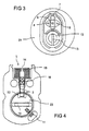
- Fig. 3 schematically shows in a front view a cylinder 21 of a locking system 30.
- an antenna 7 is fixed, the antenna 7 is placed above the insertion opening 13 for keys.
- Such keys 40 are in Fig. 6 shown.
- the insertion opening 13 is arranged within the rotor 23 of the mechanical cylinder 21.
- a display device 6 is arranged on the front side of the cylinder 21 for indicating the status of the electronic blocking device 1 and thus the blocking or non-blocking of the locking system 30.
- emergency power plugs 8 are arranged on the front side of the cylinder 21 to ensure a power supply to the locking system 30, in particular to the electronic blocking device 1 in cases of failure of the normal power supply to the electronic blocking device 1.
- Fig. 4 schematically shows a sectional view of a drive mechanism 3 of a blocking device 1 and a rotor 23 of a cylinder 21 of the locking system 30.
- the blocking element 2 is inserted into the receiving device 22 of the rotor 23. That means in Fig. 4 a movement of the rotor 23 is blocked by the blocking element 2 of the electronic blocking device 1.
- the drive mechanism 3 may have an air outlet opening 14, a magnetic compensation device 15 and a self-centering tip 16.
- the blocking element 2 is coupled to the self-centering tip 16 and can be moved by movement of the self-centering tip 16.
- an insertion opening 13 for keys 14 is arranged.
- a sensor 11 is disposed adjacent to the rotor 23 for detecting the status of the rotor 23.
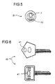
- Fig. 5 shows once again a cylinder 21 of a locking system 30 schematically in a front view. About the insertion opening 13 for key 40, the antenna 7 is arranged.
- Fig. 6 shows two keys 40 with chips 41, in particular transponder chips, which are arranged on the key head.
- the transponder chip 41 may be disposed directly in the key head or in a chip holder attached to the key head.
- a transponder signal is sent to the antenna 7 and transmitted from there to the control device 4 of the electronic locking device 1.
- Such special keys 40 may therefore send an authorization to the locking system 30 to allow the locking or unlocking of the locking system 30 and thus a door, window or the like.
Landscapes
- Physics & Mathematics (AREA)
- Electromagnetism (AREA)
- Engineering & Computer Science (AREA)
- Computer Networks & Wireless Communication (AREA)
- General Physics & Mathematics (AREA)
- Lock And Its Accessories (AREA)
- Power-Operated Mechanisms For Wings (AREA)
Applications Claiming Priority (1)
| Application Number | Priority Date | Filing Date | Title |
|---|---|---|---|
| DE201110050492 DE102011050492A1 (de) | 2011-05-19 | 2011-05-19 | Elektronische Blockiereinrichtung zum Hinzufügen zu einer manuell betätigbaren Sperrvorrichtung einer Tür, eines Fensters oder Dergleichen und Schließsystem |
Publications (2)
| Publication Number | Publication Date |
|---|---|
| EP2525026A2 true EP2525026A2 (fr) | 2012-11-21 |
| EP2525026A3 EP2525026A3 (fr) | 2017-11-08 |
Family
ID=46027510
Family Applications (1)
| Application Number | Title | Priority Date | Filing Date |
|---|---|---|---|
| EP12002339.5A Withdrawn EP2525026A3 (fr) | 2011-05-19 | 2012-03-30 | Dispositif de blocage électronique pour l'intégration dans un dispositif de blocage à actionnement manuel d'une porte, d'une fenêtre ou analogue et système de fermeture |
Country Status (5)
| Country | Link |
|---|---|
| US (1) | US20120313383A1 (fr) |
| EP (1) | EP2525026A3 (fr) |
| CN (1) | CN102787756B (fr) |
| DE (1) | DE102011050492A1 (fr) |
| NO (1) | NO20120545A1 (fr) |
Cited By (3)
| Publication number | Priority date | Publication date | Assignee | Title |
|---|---|---|---|---|
| EP3388602A1 (fr) * | 2017-04-12 | 2018-10-17 | ALSTOM Transport Technologies | Système modulaire de verrouillage d'une porte d'accès à un espace, avec éléments réversibles |
| EP3626917A1 (fr) * | 2018-09-24 | 2020-03-25 | Hoppe Ag | Poignée de commande pourvue de système de contrôle d'accès |
| US12300835B2 (en) | 2019-10-02 | 2025-05-13 | Honeywell International Inc. | Battery carrier |
Families Citing this family (10)
| Publication number | Priority date | Publication date | Assignee | Title |
|---|---|---|---|---|
| US9187929B2 (en) * | 2011-09-18 | 2015-11-17 | Hanchett Entry Systems, Inc. | Electronic cabinet/drawer lock system |
| CN103093527B (zh) * | 2012-12-28 | 2016-01-13 | 深圳市互信互达科技有限公司 | 一种基于rfid技术的一体化读卡机柜锁 |
| FI124704B (fi) * | 2013-04-17 | 2014-12-15 | Rollock Oy | Järjestely oven lukon tilan indikoimiseksi indikointivaloilla sekä peitelevy |
| AU2017345308B2 (en) | 2016-10-19 | 2023-06-29 | Dormakaba Usa Inc. | Electro-mechanical lock core |
| WO2019051337A1 (fr) | 2017-09-08 | 2019-03-14 | Dormakaba Usa Inc. | Partie centrale de verrou électromécanique |
| US11466473B2 (en) | 2018-04-13 | 2022-10-11 | Dormakaba Usa Inc | Electro-mechanical lock core |
| AU2019252796B2 (en) | 2018-04-13 | 2022-04-28 | Dormakaba Usa Inc. | Electro-mechanical lock core |
| CN108798278B (zh) * | 2018-06-20 | 2019-09-27 | 合肥美的智能科技有限公司 | 用于门体组件的电插锁、门体组件和自动售货机 |
| US10961746B2 (en) | 2018-09-20 | 2021-03-30 | Dormakaba Usa Inc. | Mortise lock and mortise lock systems and methods |
| GB2593480A (en) * | 2020-03-24 | 2021-09-29 | Squire Henry & Sons | An electronic locking device |
Family Cites Families (17)
| Publication number | Priority date | Publication date | Assignee | Title |
|---|---|---|---|---|
| DE3426508A1 (de) * | 1984-07-18 | 1986-01-23 | Sachs Systemtechnik Gmbh, 8720 Schweinfurt | Schaltschlossanlage |
| FR2629123A1 (en) * | 1986-12-29 | 1989-09-29 | Ferraye Joseph | Method for blocking locks with cylinders and with tumblers |
| EP0537010A1 (fr) * | 1991-10-11 | 1993-04-14 | Ilco Unican, Inc. | Système de verrouillage de porte |
| DE9412174U1 (de) * | 1994-07-21 | 1994-11-24 | Schaeffer Apparatebau KG, 14169 Berlin | Schließsystem, insbesondere zum Sichern von Türen |
| US5617082A (en) * | 1994-11-15 | 1997-04-01 | Micro Enhanced Technology, Inc. | Electronic access control device utilizing a single microcomputer integrated circuit |
| US5802172A (en) * | 1994-12-05 | 1998-09-01 | Independent Technologies, Inc. | Electronic lock for coin telephones |
| EP0730073A2 (fr) * | 1995-03-03 | 1996-09-04 | Kaba Schliesssysteme AG | Dispositif de verrouillage avec verrou électrique |
| DE29703063U1 (de) * | 1997-02-21 | 1997-05-15 | C. Ed. Schulte GmbH Zylinderschloßfabrik, 42551 Velbert | Schließvorrichtung mit einem Schließzylinder |
| US6374653B1 (en) * | 1997-12-22 | 2002-04-23 | Security People, Inc. | Mechanical/electronic lock and key therefor |
| US6826935B2 (en) * | 1997-12-22 | 2004-12-07 | Security People, Inc. | Mechanical/electronic lock and key therefor |
| DE19807577C1 (de) * | 1998-02-23 | 1999-04-22 | Keso Gmbh | Schließvorrichtung |
| WO2001042594A2 (fr) * | 1999-12-08 | 2001-06-14 | Winfield Locks, Inc. D.B.A. Computerized Security Systems | Verrouillage electronique |
| US6568726B1 (en) * | 2000-10-30 | 2003-05-27 | Shlomo Caspi | Universal electromechanical strike locking system |
| WO2002084043A1 (fr) * | 2001-04-11 | 2002-10-24 | Vkr Holding A/S | Dispositif de verrouillage pour fenetre d'aeration |
| DE20107870U1 (de) * | 2001-05-09 | 2002-09-19 | Bks Gmbh, 42549 Velbert | Rosette für einen zugeordneten Schließzylinder |
| US6584817B1 (en) * | 2002-08-14 | 2003-07-01 | Wfe Technology Corp. | Electronic anti-theft lock |
| DE102007038648A1 (de) * | 2007-08-15 | 2009-02-19 | Dorma Gmbh + Co. Kg | Türschloss |
-
2011
- 2011-05-19 DE DE201110050492 patent/DE102011050492A1/de not_active Withdrawn
-
2012
- 2012-03-30 EP EP12002339.5A patent/EP2525026A3/fr not_active Withdrawn
- 2012-05-11 NO NO20120545A patent/NO20120545A1/no unknown
- 2012-05-18 US US13/475,443 patent/US20120313383A1/en not_active Abandoned
- 2012-05-18 CN CN201210157939.XA patent/CN102787756B/zh active Active
Non-Patent Citations (1)
| Title |
|---|
| None |
Cited By (4)
| Publication number | Priority date | Publication date | Assignee | Title |
|---|---|---|---|---|
| EP3388602A1 (fr) * | 2017-04-12 | 2018-10-17 | ALSTOM Transport Technologies | Système modulaire de verrouillage d'une porte d'accès à un espace, avec éléments réversibles |
| FR3065244A1 (fr) * | 2017-04-12 | 2018-10-19 | Alstom Transport Technologies | Systeme modulaire de verrouillage d'une porte d'acces a un espace, avec elements reversibles |
| EP3626917A1 (fr) * | 2018-09-24 | 2020-03-25 | Hoppe Ag | Poignée de commande pourvue de système de contrôle d'accès |
| US12300835B2 (en) | 2019-10-02 | 2025-05-13 | Honeywell International Inc. | Battery carrier |
Also Published As
| Publication number | Publication date |
|---|---|
| CN102787756B (zh) | 2017-03-01 |
| CN102787756A (zh) | 2012-11-21 |
| DE102011050492A1 (de) | 2012-11-22 |
| EP2525026A3 (fr) | 2017-11-08 |
| US20120313383A1 (en) | 2012-12-13 |
| NO20120545A1 (no) | 2012-11-20 |
Similar Documents
| Publication | Publication Date | Title |
|---|---|---|
| EP2525026A2 (fr) | Dispositif de blocage électronique pour l'intégration dans un dispositif de blocage à actionnement manuel d'une porte, d'une fenêtre ou analogue et système de fermeture | |
| DE69106666T2 (de) | Elektromechanisches Türschloss. | |
| DE102007017931B4 (de) | Schwenkgriffverschluß | |
| EP0559158B1 (fr) | Cylindre de fermeture électronique | |
| DE60222261T2 (de) | Verschlusssteuerungseinrichtung mit einer Verriegelungsvorrichtung | |
| DE9403769U1 (de) | Gesteuerte Riegelbetätigungsvorrichtung | |
| EP1842989B1 (fr) | Serrure à mortaiser | |
| DE19721202A1 (de) | Einrichtung in einem Schloß, insbesondere eine elektromechanische Verriegelungsanordnung | |
| DE69002786T2 (de) | Schloss mit einem elektronischen Schlüssel. | |
| DE102013100304A1 (de) | Kupplungsvorrichtung | |
| DE112016003432T5 (de) | Elektrisches Türöffner-System mit Verriegelungsüberwachung | |
| DE3500353A1 (de) | Mechanisch und nichtmechanisch codierter schluessel sowie dadurch zu betaetigendes schloss | |
| DE3926132C2 (fr) | ||
| DE4433333A1 (de) | Nachrüstbares Hilfsverriegelungssystem für ein Einsteckschloß | |
| DE10151022A1 (de) | Kraftfahrzeug-Türschloß mit voneinander getrennter Schließeinheit und Steuereinheit | |
| EP2392752A2 (fr) | Serrure et porte, fenêtre ou analogue dotée d'une serrure | |
| DE69831311T2 (de) | Kartenschloss | |
| DE102008016698B4 (de) | Schloss mit einem Selektorelement zur Umstellung der Funktionseigenschaften des Schlosses | |
| EP2862992A2 (fr) | Multi-serrure | |
| DE102005034325A1 (de) | Beschlagsatz | |
| EP4177427B1 (fr) | Générat d'entraînement pour une fermeture | |
| DE69831688T2 (de) | Elektrische steuerungsvorrichtung zur entriegelung einer drehenden welle, insbesondere eines schlosses und schloss mit solcher vorrichtung | |
| DE19516088C2 (de) | Schloß | |
| EP3073033A1 (fr) | Serrure | |
| WO2020064772A1 (fr) | Poignée d'actionnement avec système de contrôle d'accès |
Legal Events
| Date | Code | Title | Description |
|---|---|---|---|
| PUAI | Public reference made under article 153(3) epc to a published international application that has entered the european phase |
Free format text: ORIGINAL CODE: 0009012 |
|
| AK | Designated contracting states |
Kind code of ref document: A2 Designated state(s): AL AT BE BG CH CY CZ DE DK EE ES FI FR GB GR HR HU IE IS IT LI LT LU LV MC MK MT NL NO PL PT RO RS SE SI SK SM TR |
|
| AX | Request for extension of the european patent |
Extension state: BA ME |
|
| RAP1 | Party data changed (applicant data changed or rights of an application transferred) |
Owner name: DORMA DEUTSCHLAND GMBH |
|
| RAP1 | Party data changed (applicant data changed or rights of an application transferred) |
Owner name: DORMAKABA DEUTSCHLAND GMBH |
|
| PUAL | Search report despatched |
Free format text: ORIGINAL CODE: 0009013 |
|
| AK | Designated contracting states |
Kind code of ref document: A3 Designated state(s): AL AT BE BG CH CY CZ DE DK EE ES FI FR GB GR HR HU IE IS IT LI LT LU LV MC MK MT NL NO PL PT RO RS SE SI SK SM TR |
|
| AX | Request for extension of the european patent |
Extension state: BA ME |
|
| RIC1 | Information provided on ipc code assigned before grant |
Ipc: E05B 47/06 20060101AFI20171004BHEP Ipc: E05B 19/04 20060101ALI20171004BHEP Ipc: E05B 49/00 20060101ALI20171004BHEP |
|
| STAA | Information on the status of an ep patent application or granted ep patent |
Free format text: STATUS: REQUEST FOR EXAMINATION WAS MADE |
|
| 17P | Request for examination filed |
Effective date: 20180508 |
|
| RBV | Designated contracting states (corrected) |
Designated state(s): AL AT BE BG CH CY CZ DE DK EE ES FI FR GB GR HR HU IE IS IT LI LT LU LV MC MK MT NL NO PL PT RO RS SE SI SK SM TR |
|
| STAA | Information on the status of an ep patent application or granted ep patent |
Free format text: STATUS: THE APPLICATION IS DEEMED TO BE WITHDRAWN |
|
| 18D | Application deemed to be withdrawn |
Effective date: 20180509 |