EP2525069B1 - Riss- und Delaminationsstopper für Flugzeugantriebssystemkomponenten - Google Patents
Riss- und Delaminationsstopper für Flugzeugantriebssystemkomponenten Download PDFInfo
- Publication number
- EP2525069B1 EP2525069B1 EP12250111.7A EP12250111A EP2525069B1 EP 2525069 B1 EP2525069 B1 EP 2525069B1 EP 12250111 A EP12250111 A EP 12250111A EP 2525069 B1 EP2525069 B1 EP 2525069B1
- Authority
- EP
- European Patent Office
- Prior art keywords
- fixed structure
- skin
- reinforcement members
- reinforcement
- thrust reverser
- Prior art date
- Legal status (The legal status is an assumption and is not a legal conclusion. Google has not performed a legal analysis and makes no representation as to the accuracy of the status listed.)
- Active
Links
Images






Classifications
-
- F—MECHANICAL ENGINEERING; LIGHTING; HEATING; WEAPONS; BLASTING
- F01—MACHINES OR ENGINES IN GENERAL; ENGINE PLANTS IN GENERAL; STEAM ENGINES
- F01D—NON-POSITIVE DISPLACEMENT MACHINES OR ENGINES, e.g. STEAM TURBINES
- F01D25/00—Component parts, details, or accessories, not provided for in, or of interest apart from, other groups
-
- F—MECHANICAL ENGINEERING; LIGHTING; HEATING; WEAPONS; BLASTING
- F02—COMBUSTION ENGINES; HOT-GAS OR COMBUSTION-PRODUCT ENGINE PLANTS
- F02K—JET-PROPULSION PLANTS
- F02K1/00—Plants characterised by the form or arrangement of the jet pipe or nozzle; Jet pipes or nozzles peculiar thereto
- F02K1/54—Nozzles having means for reversing jet thrust
- F02K1/56—Reversing jet main flow
- F02K1/60—Reversing jet main flow by blocking the rearward discharge by means of pivoted eyelids or clamshells, e.g. target-type reversers
-
- F—MECHANICAL ENGINEERING; LIGHTING; HEATING; WEAPONS; BLASTING
- F01—MACHINES OR ENGINES IN GENERAL; ENGINE PLANTS IN GENERAL; STEAM ENGINES
- F01D—NON-POSITIVE DISPLACEMENT MACHINES OR ENGINES, e.g. STEAM TURBINES
- F01D5/00—Blades; Blade-carrying members; Heating, heat-insulating, cooling or antivibration means on the blades or the members
- F01D5/12—Blades
- F01D5/28—Selecting particular materials; Particular measures relating thereto; Measures against erosion or corrosion
-
- F—MECHANICAL ENGINEERING; LIGHTING; HEATING; WEAPONS; BLASTING
- F02—COMBUSTION ENGINES; HOT-GAS OR COMBUSTION-PRODUCT ENGINE PLANTS
- F02K—JET-PROPULSION PLANTS
- F02K1/00—Plants characterised by the form or arrangement of the jet pipe or nozzle; Jet pipes or nozzles peculiar thereto
- F02K1/54—Nozzles having means for reversing jet thrust
-
- F—MECHANICAL ENGINEERING; LIGHTING; HEATING; WEAPONS; BLASTING
- F02—COMBUSTION ENGINES; HOT-GAS OR COMBUSTION-PRODUCT ENGINE PLANTS
- F02K—JET-PROPULSION PLANTS
- F02K1/00—Plants characterised by the form or arrangement of the jet pipe or nozzle; Jet pipes or nozzles peculiar thereto
- F02K1/54—Nozzles having means for reversing jet thrust
- F02K1/64—Reversing fan flow
-
- F—MECHANICAL ENGINEERING; LIGHTING; HEATING; WEAPONS; BLASTING
- F02—COMBUSTION ENGINES; HOT-GAS OR COMBUSTION-PRODUCT ENGINE PLANTS
- F02K—JET-PROPULSION PLANTS
- F02K1/00—Plants characterised by the form or arrangement of the jet pipe or nozzle; Jet pipes or nozzles peculiar thereto
- F02K1/54—Nozzles having means for reversing jet thrust
- F02K1/64—Reversing fan flow
- F02K1/70—Reversing fan flow using thrust reverser flaps or doors mounted on the fan housing
- F02K1/72—Reversing fan flow using thrust reverser flaps or doors mounted on the fan housing the aft end of the fan housing being movable to uncover openings in the fan housing for the reversed flow
-
- F—MECHANICAL ENGINEERING; LIGHTING; HEATING; WEAPONS; BLASTING
- F02—COMBUSTION ENGINES; HOT-GAS OR COMBUSTION-PRODUCT ENGINE PLANTS
- F02K—JET-PROPULSION PLANTS
- F02K1/00—Plants characterised by the form or arrangement of the jet pipe or nozzle; Jet pipes or nozzles peculiar thereto
- F02K1/78—Other construction of jet pipes
- F02K1/82—Jet pipe walls, e.g. liners
- F02K1/827—Sound absorbing structures or liners
-
- F—MECHANICAL ENGINEERING; LIGHTING; HEATING; WEAPONS; BLASTING
- F05—INDEXING SCHEMES RELATING TO ENGINES OR PUMPS IN VARIOUS SUBCLASSES OF CLASSES F01-F04
- F05D—INDEXING SCHEME FOR ASPECTS RELATING TO NON-POSITIVE-DISPLACEMENT MACHINES OR ENGINES, GAS-TURBINES OR JET-PROPULSION PLANTS
- F05D2250/00—Geometry
- F05D2250/70—Shape
- F05D2250/75—Shape given by its similarity to a letter, e.g. T-shaped
-
- F—MECHANICAL ENGINEERING; LIGHTING; HEATING; WEAPONS; BLASTING
- F05—INDEXING SCHEMES RELATING TO ENGINES OR PUMPS IN VARIOUS SUBCLASSES OF CLASSES F01-F04
- F05D—INDEXING SCHEME FOR ASPECTS RELATING TO NON-POSITIVE-DISPLACEMENT MACHINES OR ENGINES, GAS-TURBINES OR JET-PROPULSION PLANTS
- F05D2300/00—Materials; Properties thereof
- F05D2300/60—Properties or characteristics given to material by treatment or manufacturing
- F05D2300/603—Composites; e.g. fibre-reinforced
-
- F—MECHANICAL ENGINEERING; LIGHTING; HEATING; WEAPONS; BLASTING
- F05—INDEXING SCHEMES RELATING TO ENGINES OR PUMPS IN VARIOUS SUBCLASSES OF CLASSES F01-F04
- F05D—INDEXING SCHEME FOR ASPECTS RELATING TO NON-POSITIVE-DISPLACEMENT MACHINES OR ENGINES, GAS-TURBINES OR JET-PROPULSION PLANTS
- F05D2300/00—Materials; Properties thereof
- F05D2300/70—Treatment or modification of materials
- F05D2300/702—Reinforcement
-
- Y—GENERAL TAGGING OF NEW TECHNOLOGICAL DEVELOPMENTS; GENERAL TAGGING OF CROSS-SECTIONAL TECHNOLOGIES SPANNING OVER SEVERAL SECTIONS OF THE IPC; TECHNICAL SUBJECTS COVERED BY FORMER USPC CROSS-REFERENCE ART COLLECTIONS [XRACs] AND DIGESTS
- Y02—TECHNOLOGIES OR APPLICATIONS FOR MITIGATION OR ADAPTATION AGAINST CLIMATE CHANGE
- Y02T—CLIMATE CHANGE MITIGATION TECHNOLOGIES RELATED TO TRANSPORTATION
- Y02T50/00—Aeronautics or air transport
- Y02T50/60—Efficient propulsion technologies, e.g. for aircraft
-
- Y—GENERAL TAGGING OF NEW TECHNOLOGICAL DEVELOPMENTS; GENERAL TAGGING OF CROSS-SECTIONAL TECHNOLOGIES SPANNING OVER SEVERAL SECTIONS OF THE IPC; TECHNICAL SUBJECTS COVERED BY FORMER USPC CROSS-REFERENCE ART COLLECTIONS [XRACs] AND DIGESTS
- Y10—TECHNICAL SUBJECTS COVERED BY FORMER USPC
- Y10T—TECHNICAL SUBJECTS COVERED BY FORMER US CLASSIFICATION
- Y10T137/00—Fluid handling
- Y10T137/0536—Highspeed fluid intake means [e.g., jet engine intake]
Definitions
- US 2010/122868 discloses a nacelle inlet formed of an inner skin, an outer skin and a cellular core disposed between the inner skin and the outer skin, wherein reinforcement members extend radially from the inner skin to the outer skin to maintain structural rigidity of the nacelle during an engine blade-out event.
- the disclosure concerns protective structures for aircraft propulsion system components, which are designed to limit cracking, disbond, and delamination, thereby improving the fly-home capability of an aircraft.
- a thrust reverser inner fixed structure comprising: an inner skin; an outer skin; a cellular core disposed between the inner skin and the outer skin; and a reinforcement lattice comprising a plurality of reinforcement members extending in a thickness direction through the cellular core between the inner skin and the outer skin, wherein: each of the reinforcement members also extends in lateral direction of the cellular core, lateral directions associated with a first set of reinforcement members intersecting lateral directions associated with a second set of reinforcement members to thereby form the reinforcement lattice; wherein each reinforcement member comprises: a central segment extending radially through the cellular core, the central segment having a first end and a second end; and a first end segment extending from the first end of the central segment substantially parallel to the inner skin and bonded thereto; wherein: the outer skin is perforated; the inner skin is imperforate; the cellular core is bonded to both the inner and outer skins; and the central segment is bonded along at least a portion
- the inner fixed structure may have a "clamshell" configuration comprising two complementary halves.
- the reinforcement lattice may be found only along an enlarged barrel portion of the IFS.
- the reinforcement members may take on different cross-sectional shapes, such as a T-shaped cross-section, an I-shaped cross-section, an L-shaped cross-section, a Z-shaped cross section, a C-shaped cross section, in a lateral direction of the cellular core.
- the reinforcement member may have a first end segment secured between an acoustic cellular core and an innermost surface of the inner skin, and a central segment adhesively boned to the core.
- the reinforcement members may be bonded only to an imperforate inner skin and not bonded to a perforated outer skin.
- FIG. 1 shows a portion of an aircraft engine nacelle 1 including an exemplary acoustic inner barrel 10 at its inlet 1a.
- the barrel 10 has a 360-degree, one-piece annular construction.
- the barrel 10 includes an annular, perforated inner face sheet or inner skin 12, an annular, imperforate outer face sheet or outer skin 14 radially spaced from the inner skin 12, and an acoustic cellular core 16 disposed between the inner skin 12 and the outer skin 14.
- the term "annular” includes constructions having varying diameters and shapes along the length L ( FIG. 1 ) of the nacelle 1, and is not intended to be limited to right cylinders.
- the inner skin 12, outer skin 14 and cellular core 16 may be constructed of a composite material, such as graphite-epoxy, or the like.
- the inner skin 12 and outer skin 14 are bonded to the core 16 by an adhesive such as Henkel Epoxy Adhesive EA 9258.1, or another adhesive material having comparable peel and shear strengths, so as to have a 360-degree, one-piece construction.
- the core 16 may have a single-degree-of-freedom arrangement, a double-degree-of-freedom or a different multiple-degree-of-freedom arrangement of a type known to persons of ordinary skill in the art.
- the barrel 10 includes two crack and delamination stoppers, or reinforcement members 50 disposed approximately 180 degrees apart around the circumference of the barrel 10.
- the reinforcement members 50 extend radially from the inner skin 12, through the core 16 and to the outer skin 14.
- the reinforcement members 50 reinforce the skins 12, 14 and the core 16, and serve to limit delamination and cracking of the barrel 10 during accidents, such as a blade-out events, that may otherwise inflict structural damage on the nacelle 1.
- the reinforcement members 50 may be made of a suitably strong, lightweight material.
- a composite material, such as graphite-epoxy, is preferable, although metallic materials, such as aluminum or titanium, may also be used.
- any number and spacing of reinforcement members may be used, depending on structural needs. Where multiple reinforcement members 50 are employed, it is preferable that the reinforcement members 50 be uniformly spaced around the circumference of the barrel 10. For example, three reinforcement members 50 may be provided at approximately 120-degree spacing around the circumference of the barrel 10, or four reinforcement members 50 may be provided at approximately 90-degree spacing around the circumference of the barrel 10. It is also possible to place the reinforcement members 50 at non-uniform spacings around the barrel 10, to accommodate non-uniform structural requirements of the barrel 10.
- each reinforcement member 50 has an essentially Z-shaped cross-section in the axial direction (into the page) of the barrel 10, and includes a central segment 52 extending in a first direction D1, a first end segment 54 extending from a first end of the central segment 52 in a second direction D2 transversely (preferably, perpendicularly) to the first direction D1, and a second end segment 56 extending from a second end of the central segment 52 in a third direction D3 opposite the second direction D2.
- Each reinforcement member 50 is preferably constructed from two or more similarly shaped plies 60, 70 that are bonded together such that each channel member essentially forms a half of the reinforcement member 50.
- the reinforcement member 50 may be provided as a pre-cured composite body, wherein the plies 60, 70 are constructed of a composite material such as graphite-epoxy and bonded together by an adhesive such as 3M Scotch-Weld® Epoxy Adhesive EC-2216 B/A, or another adhesive material having comparable peel and shear strengths.
- the ply 60 may extend beyond the ply 70 in the direction D2 at the first end segment 54 in order to promote more secure attachment of the reinforcement member 50 to the inner skin 12 the barrel 10, as will be described in more detail later.
- the first end segment 54 is perforated ( FIG. 4 ) so as not to adversely impact the acoustic performance of the barrel 10.
- the reinforcement members 50 may generally have a thickness T (in the direction perpendicular to the length of a respective portion 52/54/56) of about 0.030-0.050 inches (0.076-0.127 cm). As an example, each ply 60, 70 may be about 0.0075 inches (0.019 cm) thick. However, the thickness of the reinforcement members 50 may vary as required in a given application.
- the axial length of the reinforcement members 50 (in the direction L shown in FIG. 1 ) may be approximately equal to the axial length of the core 16.
- reinforcement members 50 are shown and described as formed from two bonded plies 60, 70, such a construction is not required.
- the reinforcement members may be formed from a greater number of plies, the plies may be joined by means other than bonding, or the reinforcement members may have unitary one-piece construction.
- FIG. 4 illustrates in detail the construction of the barrel 10.
- the central segment 52 of the channel member 50 extends radially in the direction R through the core 16 of the barrel 10
- the first end segment 54 of the reinforcement member 50 extends substantially parallel to the inner skin 12 in a first direction X1
- the second end segment 56 of the reinforcement member 50 extends substantially parallel to the outer skin 14 in a second direction X2.
- the first end segment 54 is positioned between layers 12a, 12b of the inner skin 12.
- the second end segment 56 is positioned between the radially outermost surface 16a of the core 16 and the radially innermost surface 14a of the outer skin 14.
- the reinforcement member 50 is bonded to opposing surfaces of the barrel 10. Specifically, the central segment 52 is bonded to circumferentially opposing surfaces of the core 16, the first end segment 54 is bonded to the surrounding layers 12a, 12b of the inner skin 12, and the second end segment 56 is bonded to the radially opposing outer skin 14 and the outermost surface of the core 16. Because the ply 60 is longer than the ply 70 in the direction D2 at the first end segment 54, the surface area of the first end segment 54 is increased, thereby providing a larger bonding surface area between the first end segment 54 and the inner skin 12.
- the reinforcement member 50 may be bonded to the adjacent surfaces of the barrel 10 by an adhesive such as 3M Scotch-Weld® Epoxy Adhesive EC-2216 B/A, or another adhesive material having comparable peel and shear strengths.
- the second end segment 56 is not positioned between opposing individual layers (not shown) of the outer skin 14, so that the bond between the first end segment 54 and the inner skin 12 is stronger than the bond between the second end segment 56 and the outer skin 14.
- the second end segment 56 may be positioned between individual layers (not shown) of the outer skin 14, such a configuration is less desirable than the configuration shown in FIG. 4 .
- the bonds between the reinforcement members 50 and the inner skin 12 be stronger than the bonds between, the reinforcement members 50 and the outer skin 14, because such an arrangement provides optimum failure resistance characteristics.
- the engine fan blade will first strike the inner skin 12, so the inner skin 12 will be the first part of the barrel to take damage.
- the inner skin 12 includes perforations 18 that extend through the skin 12 to provide a desired flow of sound waves into the core 16.
- the first end segment 54 of the reinforcement member 50 may include perforations 58 that are substantially radially aligned with the perforations 18 so as to not detrimentally affect the flow of sound waves through the perforations 18 into the core 16.
- a reinforcement member 50 is integrated into the inner skin 12 by positioning the first end segment 54 between the inner skin layers 12a, 12b such that the layers 12a, 12b lie over the first end segment 54, and then applying adhesive to adjacent surfaces of the first end segment 54 and the inner skin layers 12a and 12b.
- One or more additional reinforcement members 50 may also be integrated into the inner skin 12 at desired locations around the periphery of the inner skin 12.
- a sub-assembly 10a is formed.
- the sub-assembly 10a is then allowed to cure in a conventional manner.
- the inner skin 12 and the first end segment 54 of each reinforcement member 50 may thereafter be perforated together, such as by drilling, sand blasting or other known technologies, so as to have aligned perforations 18, 58.
- the core 16 is bonded to the sub-assembly 10a using a suitable adhesive.
- the core 16 is bonded to the reinforcement member 50 and the inner skin 12.
- the radially innermost surface 14a of the outer skin 14 is bonded to the core 16 and the reinforcement member 50, thereby completing the barrel 10.
- the bonding techniques employed are well known to those skilled in the art.
- the inner skin 12, outer skin 14, cellular core 16 and reinforcement members 50 may be bonded together in one step to form the barrel 10, and the barrel 10 may thereafter be allowed to cure.
- the inner skin 12 and the first end segment 54 of each reinforcement member 50 may then be perforated together so as to have aligned perforations 18, 58.
- FIGS. 6 and 7 show another exemplary crack and delamination stopper or reinforcement member 150.
- the reinforcement member 150 may be used in place of the reinforcement member 50 shown in FIGS. 1-5 .
- the reinforcement member 150 has an essentially C-shaped cross section in the axial direction of the barrel 10 and includes a central segment 152 extending in a first direction D1, a first end segment 154 extending from a first end of the central segment 152 in a second direction D2 transversely to the first direction D1, and a second end segment 156 extending from a second end of the central segment 152 in the second direction D2.
- Each reinforcement member 150 is constructed from two similarly shaped plies 160, 170 that are bonded together such that each ply 160, 170 essentially forms a half of the reinforcement member 150.
- the reinforcement member 150 is provided as a pre-cured composite body.
- the ply 160 may be longer than the ply 170 in the direction D2 at the first end segment 154 in order to promote more secure integration of the reinforcement member 150 into a barrel 100 ( FIG. 8 ).
- the reinforcement member 150 may generally have a thickness T (in the direction perpendicular to the length of a respective portion 152/154/156) of about 0.030 to 0.050 inches (0.076-0.127 cm).
- the thickness of the reinforcement member 150 may vary based upon the requirements of a particular application.
- the reinforcement member 150 may be formed from a different number of plies, the plies may be joined by means other than bonding, or the reinforcement members may have unitary one-piece members 150 have been perforated, the core 16 is bonded to the sub-assembly 100a, and outer skin 14 is bonded to the core 16 using a suitable adhesive.
- the core 16 is bonded to the reinforcement members 50 and the inner skin 12.
- the radially innermost surface 14a of the outer skin 14 is bonded to the core 16 and the reinforcement members 150, thereby completing the barrel 100.
- the inner skin 12, outer skin 14, cellular core 16 and reinforcement members 150 may be bonded together in one step to form the barrel 100, and the barrel 100 may thereafter be allowed to cure.
- the inner skin 12 and the first end segment 154 of each reinforcement member 150 may then be perforated together so as to have aligned perforations 18, 158.
- the reinforcement member 250 When assembled from its components, the reinforcement member 250 has a substantially I-shaped cross-section in the axial direction of the barrel 200 and includes an elongate central segment 252 extending in a first direction D1, a first end segment 254 extending transversely to the central segment 252 in directions D2, D3, and a second end segment 256 extending from a second end of the central segment 252 transversely in directions D2, D3 to the central segment 252.
- the central segment 252 may include a bowed region 252a having an arcuate cross-section.
- the reinforcement member 250 may be provided as a pre-cured composite body constructed of graphite-epoxy or the like. As shown in FIGS. 9 and 10 , the reinforcement member 250 is constructed of a first substantially C-shaped member 260 and a second substantially C-shaped member 270 joined together in back-to-back relationship.
- the first substantially C-shaped member 260 is formed from two similarly shaped plies 262, 264 that are bonded together.
- the second substantially C-shaped member 270 is formed from two similarly shaped plies 272, 274 that are bonded together.
- the plies 262, 272 extend further in the directions D2, D3 than the plies 264, 274.
- the bowed region 252a is formed from bowed regions in the plies 262, 264 and 272, 274 that assist in alignment of the plies.
- the end segments 254, 256 may generally have a thickness T (in the direction perpendicular to the length of the respective segment 254/256) of about 0.5 inches (1.27 cm), while the central segment 252 may have a thickness T2 (in the direction perpendicular to the length of the segment 252) of about 1 inch (2.54cm).
- the thickness of the reinforcement member 250 may vary as required.
- the axial length of the reinforcement member 250 (in the direction L shown in FIG. 1 ) may be approximately equal to the axial length of the core 16.
- the reinforcement member 250 may have a different number of multiple plies, the plies may be joined by means other than bonding, or the reinforcement member may have unitary one-piece construction.
- FIG. 11 illustrates the construction of the barrel 200 including the reinforcement member 250.
- the central segment 252 of the reinforcement member 250 extends radially in the direction R through the core 16 of the barrel 200
- the first end segment 254 of the reinforcement member 250 extends substantially parallel to the inner skin 12 in directions X1, X2
- the second end segment 256 of the channel member 50 extends substantially parallel to the outer skin 14 in directions X1, X2.
- the first end segment 254 is positioned between opposing layers 12a, 12b of the inner skin 12
- the second end segment 256 is positioned between the radially innermost surface 14a of the outer skin 14 and the radially outermost surface 16a of the core 16.
- the second end portion 256 of the reinforcement member 250 may be positioned between individual layers (not shown) of the outer skin 14. As in the previously discussed barrels 10, 100, it is less preferable to position the second end portion 256 between individual layers of the outer skin 14, as it is desirable that the bond between the reinforcement member 250 and the inner skin 12 be stronger than the bond between the reinforcement member 250 and the outer skin 14.
- the first end segment 254 of the reinforcement member 250 is preferably provided with perforations 258 that are substantially aligned with the perforations 18 in the inner skin 12.
- the reinforcement member 250 is integrated into the inner skin 12 by positioning the first end segment 254 between the inner skin layers 12a, 12b such that the layers 12a, 12b lie over the first end segment 254, and applying adhesive to adjacent surfaces of the first end segment 254 and the inner skin layers 12a, 12b.
- One or more additional reinforcement members 250 may also be integrated into the inner skin 12 at desired locations around the periphery of the inner skin 12.
- a sub-assembly 200a including the inner skin 12 and the reinforcement members 250 is formed.
- the sub-assembly 200a is then allowed to cure.
- the inner skin 12 and the first end segment 254 of each reinforcement member 250 may then be perforated together so as to have aligned perforations 18, 258.
- the core 16 is bonded to the sub-assembly 200a.
- the core 16 is bonded to the reinforcement members 250 and the inner skin 12.
- the radially innermost surface 14a of the outer skin 14 is bonded to the core 16 and the reinforcement members 250.
- the inner skin 12, outer skin 14, cellular core 16 and reinforcement members 250 may be bonded together in one step to form the barrel 200, and the barrel 200 may thereafter be allowed to cure.
- the inner skin 12 and the first end segment 254 of each reinforcement member 250 may then be perforated together so as to have aligned perforations 18, 258.
- Fig. 12 shows one embodiment of an assembled, complete aircraft propulsion assembly 300 and Fig. 13 shows an exploded view of the aircraft propulsion assembly of Fig. 12 .
- the principal components of the aircraft propulsion system include an engine assembly 302 at the tail end of which are an exhaust cone 304 and an exhaust nozzle 306.
- the forward end of the engine assembly 302 is provided with a nacelle inlet 310 having a nacelle inlet lip 312.
- the nacelle inlet 310 may be of the sort having reinforcement members, as described above.
- Aft of the nacelle inlet 310 is fan cowl 320 comprising fan cowl halves 322, 324.
- a thrust reverser 330 comprising thrust reverser halves 332, 334 is aft of the fan cowl 320.
- a pylon/strut assembly 340 connects the aforementioned component to a wing of an aircraft.
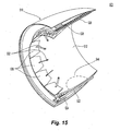
- Figs. 14 , 15 and 16 show details of a thrust reverser 400 representative of the thrust reverser 330 seen in Figs. 12 and 13 .
- the thrust reverser 400 includes an outer fixed structure 410, a translating sleeve 500, and an inner fixed structure 810.
- the outer fixed structure 410 is provided with such features as a fan cowl land 460, an outer groove 472 mated to the engine assembly 302 and other forward skin 12 at desired locations around the periphery of the inner skin 12.
- a sub-assembly 200a including the inner skin 12 and the reinforcement members 250 is formed.
- the sub-assembly 200a is then allowed to cure.
- the inner skin 12 and the first end segment 254 of each reinforcement member 250 may then be perforated together so as to have aligned perforations 18, 258.
- the core 16 is bonded to the sub-assembly 200a.
- the core 16 is bonded to the reinforcement members 250 and the inner skin 12.
- the radially innermost surface 14a of the outer skin 14 is bonded to the core 16 and the reinforcement members 250.
- the inner skin 12, outer skin 14, cellular core 16 and reinforcement members 250 may be bonded together in one step to form the barrel 200, and the barrel 200 may thereafter be allowed to cure.
- the inner skin 12 and the first end segment 254 of each reinforcement member 250 may then be perforated together so as to have aligned perforations 18, 258.
- Fig. 12 shows one embodiment of an assembled, complete aircraft propulsion assembly 300 and Fig. 13 shows an exploded view of the aircraft propulsion assembly of Fig. 12 .
- the principal components of the aircraft propulsion system include an engine assembly 302 at the tail end of which are an exhaust cone 304 and an exhaust nozzle 306.
- the forward end of the engine assembly 302 is provided with a nacelle inlet 310 having a nacelle inlet lip 312.
- the nacelle inlet 310 may be of the sort having reinforcement members, as described above.
- Aft of the nacelle inlet 310 is fan cowl 320 comprising fan cowl halves 322, 324.
- a thrust reverser 330 comprising thrust reverser halves 332, 334 is aft of the fan cowl 320.
- a pylon/strut assembly 340 connects the aforementioned component to a wing of an aircraft.
- Figs. 14 , 15 and 16 show details of a thrust reverser 400 representative of the thrust reverser 330 seen in Figs. 12 and 13 .
- the thrust reverser 400 includes an outer fixed structure 410, a translating sleeve 500, and an inner fixed structure 810.
- the outer fixed structure 410 is provided with such features as a fan cowl land 460, an outer groove 472 mated to the engine assembly 302 and other forward components in the assembled system. Also provided on the outer fixed structure 410 is a torque box assembly 440 and a plurality of actuators 430 which are operatively connected to the translating sleeve 500. Cascades 450, which terminate in the aft direction at an aft cascade attached frame 452, are provided on the outer fixed structure 410 to selectively redirect fan exhaust depending on the mode (forward or reverse) of the thrust reverser 400.
- the translating sleeve 500 includes an outer panel assembly 510, an inner panel assembly 512, lower inner and outer sliders 522, 524, and upper inner and outer sliders 526, 528.
- An inner circumferential periphery of the sleeve 500 is provided with a plurality of hinged blocker doors 530 arranged side-by-side. Each blocker door 530 is connected via a blocker door link 532 to a hinged mount 534 affixed to an outer portion of the inner fixed structure 810.
- the translating sleeve 500 is further connected to the inner fixed structure 810 by the lower inner and outer sliders 522, 524 and the upper inner and outer sliders 526, 528 which engage tracks 560 belonging to the inner fixed structure 810.
- the inner panel assembly 512 is locally flattened in a predetermined region 544 to attach the inner sliders.
- the blocker doors 530 When the blocker doors 530 are closed (forward thrust mode), they cover the cascades 450 and when the blocker doors 530 are open (reverse thrust mode), the cascades are no longer covered and so permit fan exhaust to pass therethrough.
- the translating sleeve 500 moves between a first position in which the thrust reverser 400 is in forward thrust mode and a second position in which the assembly is in the reverse thrust mode.
- the actuators 430 mounted on the outer fixed structure 410 cause the translating sleeve 500 to move between the first and second positions.
- the translating sleeve 500 forms the nacelle external surface and shields the cascades 450 from exhaust gases.
- the reverse thrust mode the translating sleeve 500 slides in the aft direction. This deploys the blocker doors 530, exposes the cascades 450, and redirects fan exhaust in a forward direction.
- Prior art thrust reverser inner fixed structures having portions comprising an inner skin, and outer skin and a cellular core, which may be an acoustic cellular core, are known. In such constructions, the inner and outer skins are bonded to the cellular core.
- disbonding of the inner or outer skin from the core has been an issue in the nacelle industry, in some instances resulting in parts of the inner fixed structure detaching and even departing from the aircraft. Disbonding may result from the degradation of the bond line between the cellular core and one or more of the inner skin and outer skin due to long exposure to high temperatures of the sort created by exhaust gases.
- providing a thrust reverser inner fixed structure with reinforcement members such as those discussed above with respect to an inner barrel, may be one way to mitigate the effects of disbonding with minimal added cost and weight.
- Fig. 17 shows a thrust reverser half 332a which exposes one half section 890 ("IFS Section") of an inner fixed structure formed in two "clam-shell” halves, only one clam-shell half 890 being shown. It is understood that the unseen second section is essentially a mirror image of seen section 890.
- the IFS section has a forward end 860 which faces in the direction of the engine and fan cowl and an aft end 862 which faces in the direction of the exhaust nozzle.
- the IFS halves 890 are connected together by latches 870 at the bottom and hinged to the pylon 340 at the top.
- Bumpers 480 provide a structural bridge between the gaps that separates the two IFS halves 890. The structural bridge provides a hoop load path to resist the crushing pressure of the fan air stream upon the barrel sections and bifurcations.
- the inner fixed structure seen in Fig. 17 is constructed to encase portions of the engine assembly located between the engine fan case and the nozzle.
- the inner fixed structure is configured to create an aerodynamically smooth path for air and creates a fire and heat boundary by enclosing portions of the engine assembly.
- the inner fixed structure section 890 is a one-piece honeycomb sandwich comprising an inner skin, an outer skin and a cellular core between the inner and outer skins, all bonded together.
- the honeycomb sandwich is typically an acoustic structure with an imperforate inner skin 820, a perforated outer skin 822, and a cellular core 824 suitable for use in acoustic applications.
- the inner skin 820 may be formed from a metallic or a graphite composite material; the outer skin may also be formed from a metallic or graphite composite material; and the cellular core 824 may be formed from a metallic material such as aluminum or titanium, or may even be formed from a non-metallic material, such as a graphite composite material.
- the inner fixed structure section 890 has an upper bifurcation wall portion 802, a lower bifurcation wall portion 804 and a barrel portion 806 formed between the two wall portions 802, 804.
- the honeycomb sandwich is acoustic wherever possible to control noise, but is interrupted by a number of structures and formations such as cooling holes 812, bumpers 480, latches 870, mounting members and the like.
- the diameter of the barrel portion 806 increases to form an enlarged barrel portion 808 of suitable size and shape to enclose the rear engine mounts and the turbine section of the engine.
- the barrel portion 806 then decreases in diameter to wrap around the forward portion of the exhaust nozzle 306.
- the honeycomb sandwich in at least the enlarged barrel portion 808 of the inner fixed structure section 890 is provided with a reinforcement lattice 815.
- the reinforcement lattice is provided only in the enlarged barrel portion 808.
- the reinforcement lattice 815 comprises a plurality of reinforcement members 817, 819 extending in a thickness direction through the cellular core 824 between the "back" or inner skin 820 and the outer skin 822.
- Reinforcement members 817, which extend in a first direction, constitute a first set of reinforcement members
- reinforcement members 819 which extend in a second direction, constitute a second set of reinforcement members, the two directions intersecting.
- Each of the reinforcement members also extends in lateral direction through the cellular core 824, the lateral directions being perpendicular to the thickness direction of the cellular core 824.
- the lateral directions associated with a first set of reinforcement members 817 intersect lateral directions associated with a second set of reinforcement members 819 to thereby form the reinforcement lattice 815.
- the reinforcement members themselves may intersect.
- a first reinforcement member may be broken while a second reinforcement member continues unbroken.
- the broken reinforcement member may be bonded to transversely extending opposite side walls of the unbroken reinforcement member.
- special "cross-shaped" intersection members may be provided, with the "broken" ends of the two intersecting reinforcement members being bonded to legs of the "cross-shaped" intersection members.”
- At least two longitudinal reinforcement members 817 extend along a longitudinal direction of the inner fixed structure section 890, while at least two circumferential reinforcement members 819 extend along a circumferential direction of the inner fixed structure section 890. Furthermore, as seen in this figure, the longitudinal reinforcement members 817 intersect the circumferential reinforcement members 819 to form the reinforcement lattice 815.
- a complete thrust reverser inner fixed structure 810 two complementary sections 890 are arranged in a clamshell configuration, each section including such a reinforcement lattice 815. It is further understood that one may instead form a one-piece thrust reverser inner fixed structure (not shown) which may have two such reinforcement lattices 815 facing each other in the enlarged barrel portion 808.
- the reinforcement members 830, 840 may take on different cross-sectional shapes.
- T-shaped cross-sectional member 830 has a central segment 832 having a first end 836 and a second end 838.
- the central segment 832 extends radially through the cellular core 824 and is connected at its first end 836 to a first end segment 834.
- the first end segment 834 extends substantially parallel to the inner skin 820 and is bonded thereto, such as in the manner described previously with respect to the inner barrel.
- the central segment 832 is bonded to cellular core 824 by adhesive bonding, by diffusion bonding, or in some other manner. In the case of adhesive bonding, a foam adhesive may be employed.
- the central segment 832 is anchored to the cellular core 824 while the first end segment 834 is anchored to the inner skin 820.
- the outer skin 822 typically is not bonded to the reinforcement member 830 and, in some embodiments the second end 838 of the central segment 832 may not even extend to the outer skin 822 and so the reinforcement member 830 may be spaced apart therefrom.
- the central segment 832 of the T-shaped cross-sectional member has a thickness of about 0.044 inches while the first end segment 834 of the T-shaped cross-sectional member has a thickness of about 0.022 inches.
- the T-shaped cross-sectional member 830 may be formed by folding a sheet of material having a thickness of about 0.022 inches on itself to form the central segment 832, and further fold the ends outwardly to create a T-shaped cross-section. The folded sheet may then be pre-cured before incorporation into the cellular core 824. Alternatively, in some embodiments, the folded sheet may be co-cured with the inner and/or outer skins.
- L-shaped cross-sectional member 840 has a central segment 842 having a first end 846 and a second end 848.
- the central segment 842 extends radially through the cellular core 824 and is connected at its first end 846 to a first end segment 844.
- the first end segment 844 extends substantially parallel to the inner skin 820 and is bonded thereto, such as in the manner described previously with respect to the inner barrel.
- the central segment 842 is bonded to cellular core by adhesive bonding, by diffusion bonding, or in some other manner. In the case of adhesive bonding, a foam adhesive may be employed.
- the central segment 842 is anchored to the cellular core 824 while the first end segment 844 is anchored to the inner skin 820.
- the outer skin 822 typically is not bonded to the reinforcement member 840 and, in some embodiments the second end 848 of the central segment 842 may not even extend to the outer skin 822 and so the reinforcement member 840 may be spaced apart therefrom.
- the central segment 842 and the first end segment 844 of the L-shaped member both have a thickness of 0.022 inches.
- the L-shaped cross-sectional member 840 may be formed by folding a sheet of material having a thickness of about 0.022 inches to create an L-shaped cross-section. The folded sheet may then be pre-cured before incorporation into the cellular core 824. Alternatively, in some embodiments, the folded sheet may be co-cured with the inner and/or outer skins.
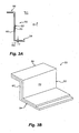
- Figs. 18A and 18B show cross-sections of two specific embodiments of reinforcement members, it is understood that reinforcement members may have some other cross-section, such as an I-shape, a C-shape, a Z-shape, as described above.
- the first end segment is bonded to the inner skin and the central segment is bonded to the cellular core.
- the outer skin may not be bonded to the reinforcement member, even though the second end of the central segment of the reinforcement member is proximate to an inner surface of the outer skin.
- the "second end segment" proximate the second end of the central section is adhesively anchored to the core 824, thereby providing additional surface area to resist disbonding.
- the embodiments disclosed herein improve the fly-home capability of aircraft during blade-out events, disbonding events and other events that may inflict damage on aircraft propulsion system components, such as the acoustic inner barrel of an aircraft engine nacelle or the inner fixed structure of a thrust reverser.
- aircraft propulsion system components such as the acoustic inner barrel of an aircraft engine nacelle or the inner fixed structure of a thrust reverser.
- the disclosed reinforcement members function to limit crack propagation and/or disbonding. And due to their design and orientation, the reinforcement members also should not significantly affect the sound dampening performance of these components.
Landscapes
- Engineering & Computer Science (AREA)
- Mechanical Engineering (AREA)
- General Engineering & Computer Science (AREA)
- Chemical & Material Sciences (AREA)
- Combustion & Propulsion (AREA)
- Materials Engineering (AREA)
- Laminated Bodies (AREA)
- Soundproofing, Sound Blocking, And Sound Damping (AREA)
- Structures Of Non-Positive Displacement Pumps (AREA)
Claims (12)
- Innere fixierte Struktur (810) einer Schubumkehrvorrichtung, umfassend:eine Innenverkleidung (820);eine Außenverkleidung (822);einen zellularen Kern (824), der zwischen der Innenverkleidung und der Außenverkleidung angeordnet ist; undein Verstärkungsgitter (815), umfassend eine Vielzahl von Verstärkungselementen (817, 819), die sich in eine Dickenrichtung durch den zellularen Kern zwischen der Innenverkleidung und der Außenverkleidung erstreckt, wobei:sich jedes der Verstärkungselemente ebenfalls in eine laterale Richtung des zellularen Kerns erstreckt, wobei laterale Richtungen, die mit einem ersten Satz von Verstärkungselementen assoziiert sind, laterale Richtungen schneiden, die mit einem zweiten Satz von Verstärkungselementen assoziiert sind, um dadurch das Verstärkungsgitter auszubilden;wobei jedes Verstärkungselement Folgendes umfasst:ein zentrales Segment (832), das sich radial durch den Zellkern erstreckt, wobei das zentrale Segment ein erstes Ende (836) und ein zweites Ende (838) aufweist; undein erstes Endsegment (834), das sich vom ersten Ende des zentralen Segments im Wesentlichen parallel zu der Innenverkleidung erstreckt und daran befestigt ist;dadurch gekennzeichnet, dassdie Außenverkleidung perforiert ist;die Innenverkleidung nicht perforiert ist;der zellulare Kern an der Innen- und Außenverkleidung befestigt ist; unddas zentrale Segment entlang von mindestens einem Abschnitt seiner Länge an dem zellularen Kern befestigt ist; undwobei sich das zweite Ende jedes zentralen Segments in der Nähe der Außenverkleidung befindet und die Außenverkleidung nicht an beliebigen der Verstärkungselemente befestigt ist.
- Innere fixierte Struktur (810) einer Schubumkehrvorrichtung nach Anspruch 1, wobei:
das Verstärkungsgitter (815) in einem vergrößerten Trommelabschnitt (808) der inneren fixierten Struktur bereitgestellt ist, wobei der vergrößerte Trommelabschnitt zwischen einem oberen und einem unteren Gabelungswandabschnitt (802, 804) der inneren fixierten Struktur platziert ist. - Innere fixierte Struktur (810) einer Schubumkehrvorrichtung nach Anspruch 2, wobei:
das Verstärkungsgitter (815) nur in dem vergrößerten Trommelbereich (808) der inneren fixierten Struktur bereitgestellt ist. - Innere fixierte Struktur (810) einer Schubumkehrvorrichtung nach Anspruch 1, wobei:
jedes der Innenverkleidung (820), der Außenverkleidung (822), des zellularen Kerns (824) und der Verstärkungselemente (817, 819) aus einem Graphitverbundmaterial konstruiert ist. - Innere fixierte Struktur (810) einer Schubumkehrvorrichtung nach Anspruch 1, wobei:
mindestens zwei Verstärkungselemente (817, 819), die zu dem ersten Satz gehören, mindestens zwei Verstärkungselemente schneiden, die zu dem zweiten Satz gehören. - Innere fixierte Struktur (810) einer Schubumkehrvorrichtung nach Anspruch 1, umfassend:mindestens zwei Längsverstärkungselemente (817), die sich entlang einer Längsrichtung der inneren fixierten Struktur erstrecken; undmindestens zwei Umfangsverstärkungselemente (819), die sich entlang einer Umfangsrichtung der inneren fixierten Struktur erstrecken; wobei:
die mindestens zwei Längsverstärkungselemente die mindestens zwei Umfangsverstärkungselemente schneiden. - Innere fixierte Struktur (810) einer Schubumkehrvorrichtung nach Anspruch 1, umfassend zwei komplementäre Teilbereiche (890) der inneren fixierten Struktur, die in einer Muschelschalenkonfiguration angeordnet sind, wobei jeder Teilbereich der inneren fixierten Struktur Folgendes beinhaltet:mindestens zwei Verstärkungselemente (817), die sich entlang einer ersten lateralen Richtung erstrecken; undmindestens zwei Verstärkungselemente (819), die sich entlang einer zweiten lateralen Richtung erstrecken.
- Innere fixierte Struktur (810) einer Schubumkehrvorrichtung nach Anspruch 1, wobei:das erste Endsegment (834) adhäsiv an der Innenverkleidung (820) befestigt ist; unddas zentrale Segment (832) adhäsiv an dem zellularen Kern (824) befestigt ist.
- Innere fixierte Struktur (810) einer Schubumkehrvorrichtung nach Anspruch 1, wobei:
jedes Verstärkungselement (817, 819) einen Querschnitt in einer lateralen Richtung der inneren fixierten Struktur aufweist, wobei der Querschnitt eine I-Form oder eine T-Form aufweist. - Innere fixierte Struktur (810) einer Schubumkehrvorrichtung nach Anspruch 9, wobei, wenn der Querschnitt eine I-Form ist, die I-Form ein erstes C-förmiges Element umfasst, das mit einem zweiten C-förmigen Element in einer Rücken-an-Rücken-Beziehung verbunden ist.
- Flugzeugantriebssystem, beinhaltend ein Triebwerk und eine Schubumkehrvorrichtung (400), wobei:
die Schubumkehrvorrichtung die innere fixierte Struktur (810) der Schubumkehrvorrichtung nach einem der vorhergehenden Ansprüche umfasst. - Flugzeugantriebssystem nach Anspruch 11, ferner umfassend:eine Triebwerksgondel (1) mit einer akustischen inneren Trommel (10), umfassend:eine ringförmige Innenverkleidung (12);eine ringförmige Außenverkleidung (14);einen ringförmigen akustischen zellularen Kern (16), der zwischen der Innenverkleidung und der Außenverkleidung angeordnet ist; undmindestens zwei Verstärkungselemente (50, 150, 250), die sich radial von der Innenverkleidung, durch den akustischen zellularen Kern und zu der Außenverkleidung erstrecken,wobei die Innenverkleidung, die Außenverkleidung, der akustische zellulare Kern und die mindestens zwei Verstärkungselemente aneinander befestigt sind, um eine einstückige ringförmige 360-Grad-Struktur auszubilden.
Applications Claiming Priority (1)
| Application Number | Priority Date | Filing Date | Title |
|---|---|---|---|
| US201161488659P | 2011-05-20 | 2011-05-20 |
Publications (3)
| Publication Number | Publication Date |
|---|---|
| EP2525069A2 EP2525069A2 (de) | 2012-11-21 |
| EP2525069A3 EP2525069A3 (de) | 2017-05-10 |
| EP2525069B1 true EP2525069B1 (de) | 2020-08-12 |
Family
ID=46229386
Family Applications (1)
| Application Number | Title | Priority Date | Filing Date |
|---|---|---|---|
| EP12250111.7A Active EP2525069B1 (de) | 2011-05-20 | 2012-05-18 | Riss- und Delaminationsstopper für Flugzeugantriebssystemkomponenten |
Country Status (3)
| Country | Link |
|---|---|
| US (2) | US9016042B2 (de) |
| EP (1) | EP2525069B1 (de) |
| CN (1) | CN102795351B (de) |
Families Citing this family (19)
| Publication number | Priority date | Publication date | Assignee | Title |
|---|---|---|---|---|
| DE102011004844A1 (de) * | 2011-02-28 | 2012-08-30 | Airbus Operations Gmbh | Türrahmenverbund, Rumpfabschnitt sowie Luft- oder Raumfahrzeug |
| US9016042B2 (en) * | 2011-05-20 | 2015-04-28 | Rohr, Inc. | Reinforcement members for aircraft propulsion system components configured to address delamination of the inner fixed structure |
| WO2014151097A1 (en) * | 2013-03-15 | 2014-09-25 | United Technologies Corporation | Reinforced composite case |
| FR3005100B1 (fr) * | 2013-04-26 | 2015-05-01 | Snecma | Carter de turbomachine |
| EP3019724B1 (de) * | 2013-07-09 | 2018-04-11 | United Technologies Corporation | Vorgeladener hinterer entlüftungsbereich für ein niederdruck-lüftungsgebläse |
| EP3055541B1 (de) * | 2013-10-07 | 2021-12-08 | Rohr, Inc. | Feste hybrid-innenstruktur mit einer metallischen verbundkonstruktion |
| EP3055087B1 (de) * | 2013-10-10 | 2018-05-30 | Rohr, Inc. | Verfahren zur herstellung einer komplex gekrümmten metallsandwichplatte |
| US9951652B2 (en) * | 2013-12-05 | 2018-04-24 | Rohr, Inc. | Aircraft thrust reversing assembly IFS support structure |
| US9835112B2 (en) * | 2014-02-10 | 2017-12-05 | MRA Systems Inc. | Thrust reverser cascade |
| US9649728B2 (en) * | 2014-11-02 | 2017-05-16 | Spirit Aerosystems, Inc. | Bifurcation honeycomb sandwich structure with optimized doubler |
| US9469985B1 (en) * | 2015-05-11 | 2016-10-18 | Hexcel Corporation | Acoustic structures with multiple degrees of freedom |
| GB201521075D0 (en) * | 2015-11-30 | 2016-01-13 | Short Brothers Plc | Methods, precursors and abrasive blasting masks for manufacturing noise attenuating devices |
| US10253727B2 (en) * | 2016-05-12 | 2019-04-09 | Rohr, Inc. | Backside acoustic treatment of nacelle structural fittings |
| US10759541B2 (en) | 2016-10-14 | 2020-09-01 | Rohr, Inc. | Nacelle bifurcation with leading edge structure |
| US10473030B2 (en) * | 2017-03-07 | 2019-11-12 | Rolls-Royce Corporation | Acoustic panel of turbine engine |
| CN108454888B (zh) * | 2018-01-31 | 2021-02-19 | 倪惠芳 | 一种航空航天驱动设备辅助装置 |
| FR3095158B1 (fr) * | 2019-04-17 | 2021-04-30 | Hutchinson | Procédé de fabrication d’une grille pour un inverseur de poussée |
| US12071858B2 (en) * | 2021-10-13 | 2024-08-27 | General Electric Company | Fire retardant engine casing apparatus |
| FR3163197A1 (fr) * | 2024-06-10 | 2025-12-12 | Airbus | Panneau d’atténuation acoustique comprenant au moins un renfort en C maintenu par au moins un noyau expansible et procédé de fabrication d’un tel panneau |
Family Cites Families (56)
| Publication number | Priority date | Publication date | Assignee | Title |
|---|---|---|---|---|
| US3297238A (en) | 1965-02-05 | 1967-01-10 | Irving R Sherman | Bypass core ducted fan with outer peripheral bearings |
| US3519228A (en) | 1967-09-29 | 1970-07-07 | Dow Chemical Co | Airfoil structure |
| US3974313A (en) * | 1974-08-22 | 1976-08-10 | The Boeing Company | Projectile energy absorbing protective barrier |
| FR2376994A1 (fr) | 1977-01-11 | 1978-08-04 | Snecma | Perfectionnements aux dispositifs a cavites resonnantes pour la reduction du bruit dans un conduit en presence d'un flux gazeux |
| US4215536A (en) | 1978-12-26 | 1980-08-05 | The Boeing Company | Gas turbine mixer apparatus |
| FR2498793A1 (fr) | 1981-01-29 | 1982-07-30 | Snecma | Garniture insonorisante pour conduit de gaz notamment pour veine de soufflante de turboreacteur et outillage pour sa fabrication |
| US4416349A (en) | 1981-09-30 | 1983-11-22 | The Boeing Company | Viscoelastically damped reinforced skin structures |
| US4425980A (en) | 1981-12-14 | 1984-01-17 | The Boeing Company | Beam dampers for damping the vibrations of the skin of reinforced structures |
| US4452563A (en) | 1981-12-21 | 1984-06-05 | United Technologies Corporation | Containment structure |
| US4452565A (en) | 1981-12-21 | 1984-06-05 | United Technologies Corporation | Containment structure |
| US4492607A (en) | 1983-02-22 | 1985-01-08 | Rockwell International Corporation | Method for producing integrally stiffened fiber reinforced plastic panels |
| US4966802A (en) | 1985-05-10 | 1990-10-30 | The Boeing Company | Composites made of fiber reinforced resin elements joined by adhesive |
| US4751979A (en) | 1985-05-16 | 1988-06-21 | Airborne Express, Inc. | Engine noise suppression kit for the nacelles of a jet aircraft |
| US4671470A (en) | 1985-07-15 | 1987-06-09 | Beech Aircraft Corporation | Method for fastening aircraft frame elements to sandwich skin panels covering same using woven fiber connectors |
| US4826106A (en) * | 1987-02-18 | 1989-05-02 | Grumman Aerospace Corporation | Advanced composite aircraft cowl |
| GB8817669D0 (en) | 1988-07-25 | 1988-09-01 | Short Brothers Ltd | Means for attenuating sound energy |
| US4944362A (en) | 1988-11-25 | 1990-07-31 | General Electric Company | Closed cavity noise suppressor |
| US4979587A (en) | 1989-08-01 | 1990-12-25 | The Boeing Company | Jet engine noise suppressor |
| US5083426A (en) * | 1989-10-02 | 1992-01-28 | Rohr Industries, Inc. | Integrated engine shroud for gas turbine engines |
| US5000399A (en) | 1990-02-23 | 1991-03-19 | General Electric Company | Variable contour annular air inlet for an aircraft engine nacelle |
| FR2661213B1 (fr) * | 1990-04-19 | 1992-07-03 | Snecma | Moteur d'aviation a tres grand taux de dilution et du type dit contrafan avant. |
| GB9014381D0 (en) | 1990-06-28 | 1990-08-22 | Short Brothers Plc | A composite structural component |
| US5297760A (en) | 1992-08-21 | 1994-03-29 | Mcdonnell Douglas Corporation | Aircraft skin lap splice |
| DE4340951A1 (de) | 1992-12-04 | 1994-06-09 | Grumman Aerospace Corp | Einstückiges Triebwerkeinlaß-Schallrohr |
| GB9301457D0 (en) | 1993-01-26 | 1993-03-17 | Short Brothers Plc | An aircraft propulsuve power unit |
| GB9407632D0 (en) | 1994-04-18 | 1994-06-08 | Short Brothers Plc | An aircraft propulsive power unit |
| US5577688A (en) | 1994-06-15 | 1996-11-26 | Sloan; Frank P. | Containment systems for insulation, and insulation elements employing such systems |
| US5658024A (en) | 1995-02-17 | 1997-08-19 | Bachmann Inc. | Expansion joint with a sloped cavity and improved fabric clamping |
| US5592813A (en) | 1995-07-06 | 1997-01-14 | Avaero | Hush kit for jet engine |
| GB9713209D0 (en) | 1997-06-20 | 1997-08-27 | British Aerospace | Friction welding metal components |
| FR2767560B1 (fr) | 1997-08-19 | 1999-11-12 | Aerospatiale | Ensemble reducteur de bruit pour turboreacteur d'aeronef |
| FR2787509B1 (fr) | 1998-12-21 | 2001-03-30 | Aerospatiale | Structure d'entree d'air pour moteur d'aeronef |
| US6340135B1 (en) | 2000-05-30 | 2002-01-22 | Rohr, Inc. | Translating independently mounted air inlet system for aircraft turbofan jet engine |
| US6530221B1 (en) | 2000-09-21 | 2003-03-11 | Siemens Westinghouse Power Corporation | Modular resonators for suppressing combustion instabilities in gas turbine power plants |
| FR2840647B1 (fr) | 2002-06-05 | 2004-10-29 | Airbus France | Dispositif pour le raccordement de deux pieces tubulaires de turboreacteur d'aeronef |
| DE10238820A1 (de) | 2002-08-23 | 2004-03-11 | Airbus Deutschland Gmbh | Anordung zur Erfindung von dünnwandigen Metallstrukturen |
| FR2844303B1 (fr) | 2002-09-10 | 2006-05-05 | Airbus France | Piece tubulaire d'attenuation acoustique pour entree d'air de reacteur d'aeronef |
| US7197852B2 (en) * | 2002-09-20 | 2007-04-03 | The Boeing Company | Internally stiffened composite panels and methods for their manufacture |
| FR2856379B1 (fr) | 2003-06-18 | 2006-11-24 | Airbus France | Moteur d'avion dont les capots de soufflante et d'inverseurs de poussee sont separes par un jeu reduit |
| US7588212B2 (en) * | 2003-07-08 | 2009-09-15 | Rohr Inc. | Method and apparatus for noise abatement and ice protection of an aircraft engine nacelle inlet lip |
| US7083147B2 (en) | 2004-03-11 | 2006-08-01 | The Boeing Company | Modularized insulation, systems, apparatus, and methods |
| US7040575B2 (en) | 2004-03-29 | 2006-05-09 | The Boeing Company | Foam composite insulation for aircraft |
| FR2868124B1 (fr) | 2004-03-29 | 2006-06-23 | Airbus France Sas | Structure d'entree d'air pour moteur d'aeronef |
| US7328771B2 (en) | 2004-07-27 | 2008-02-12 | United Technologies Corporation | Zero acoustic splice fan case liner |
| US7578468B2 (en) * | 2004-12-20 | 2009-08-25 | Sikorsky Aircraft Corporation | Acoustic absorption system for an aircraft airframe |
| US7296655B2 (en) | 2005-04-22 | 2007-11-20 | United Technologies Corporation | Duct liner acoustic splice |
| CA2619767C (en) | 2005-08-19 | 2013-05-28 | Airbus Espana, S.L. | Stringers made of a composite material with a bulb |
| US7707708B2 (en) | 2005-09-21 | 2010-05-04 | Rohr, Inc. | Apparatus for making a tubular composite structure |
| US7923668B2 (en) | 2006-02-24 | 2011-04-12 | Rohr, Inc. | Acoustic nacelle inlet lip having composite construction and an integral electric ice protection heater disposed therein |
| US7866440B2 (en) | 2006-07-21 | 2011-01-11 | Rohr, Inc. | System for joining acoustic cellular panel sections in edge-to-edge relation |
| NL2000232C2 (nl) * | 2006-09-12 | 2008-03-13 | Gtm Consulting B V | Huidpaneel voor een vliegtuigromp. |
| US7503425B2 (en) | 2006-10-02 | 2009-03-17 | Spirit Aerosystems, Inc. | Integrated inlet attachment |
| GB0707099D0 (en) * | 2007-04-13 | 2007-05-23 | Rolls Royce Plc | A casing |
| JP2009062977A (ja) * | 2007-08-15 | 2009-03-26 | Rohr Inc | 線形音響ライナー |
| US7798285B2 (en) * | 2008-11-14 | 2010-09-21 | Rohr, Inc. | Acoustic barrel for aircraft engine nacelle including crack and delamination stoppers |
| US9016042B2 (en) * | 2011-05-20 | 2015-04-28 | Rohr, Inc. | Reinforcement members for aircraft propulsion system components configured to address delamination of the inner fixed structure |
-
2012
- 2012-05-11 US US13/470,049 patent/US9016042B2/en active Active
- 2012-05-18 EP EP12250111.7A patent/EP2525069B1/de active Active
- 2012-05-21 CN CN201210159337.8A patent/CN102795351B/zh active Active
- 2012-12-20 US US13/723,095 patent/US20130129483A1/en not_active Abandoned
Non-Patent Citations (1)
| Title |
|---|
| None * |
Also Published As
| Publication number | Publication date |
|---|---|
| US9016042B2 (en) | 2015-04-28 |
| CN102795351B (zh) | 2016-12-14 |
| EP2525069A3 (de) | 2017-05-10 |
| US20130129483A1 (en) | 2013-05-23 |
| US20120291416A1 (en) | 2012-11-22 |
| EP2525069A2 (de) | 2012-11-21 |
| CN102795351A (zh) | 2012-11-28 |
Similar Documents
| Publication | Publication Date | Title |
|---|---|---|
| EP2525069B1 (de) | Riss- und Delaminationsstopper für Flugzeugantriebssystemkomponenten | |
| EP2186729B1 (de) | Schallgehäuse für Flugzeugtriebwerksgondeln einschließlich Riss- und Delaminationsstopper | |
| EP2690273B1 (de) | Paneel für eine gondelstruktur | |
| US6557799B1 (en) | Acoustic treated thrust reverser bullnose fairing assembly | |
| US10738738B2 (en) | Nacelle with bifurcation extension and integral structural reinforcement | |
| US9403599B2 (en) | Inlet section of an aircraft engine nacelle | |
| US6179943B1 (en) | Method for forming a composite acoustic panel | |
| EP0895222B1 (de) | Stützstruktur für Akustikplatten einer Triebwerksgondel | |
| US10940955B2 (en) | Acoustic panel with structural septum | |
| WO2008111992A2 (en) | Monolithic thrust reverser components | |
| US9714627B2 (en) | Mounting of aircraft propulsion system outer sleeve and inner structure to pylon with distinct hinges | |
| US7735600B2 (en) | Monolithic acoustically-treated engine nacelle inlet panels | |
| CN112189089A (zh) | 用于飞行器喷气发动机短舱的声学衰减板 | |
| US10253727B2 (en) | Backside acoustic treatment of nacelle structural fittings | |
| US12595068B2 (en) | Blocker door for an aircraft thrust reverser | |
| RU2570181C2 (ru) | Узел авиационного двигателя | |
| EP3084178B1 (de) | Geschichtete eisisolierung | |
| US10161357B2 (en) | Acoustically treated thrust reverser track beam | |
| EP4045410B1 (de) | Flugzeugtriebwerksgondeleinlauf | |
| EP0895223B1 (de) | Akustikplatte für Motorgondel mit integrierte Keilverkleidung und Vorderring | |
| EP3858595A1 (de) | Akustische auskleidung und verfahren zur herstellung derselben |
Legal Events
| Date | Code | Title | Description |
|---|---|---|---|
| PUAI | Public reference made under article 153(3) epc to a published international application that has entered the european phase |
Free format text: ORIGINAL CODE: 0009012 |
|
| 17P | Request for examination filed |
Effective date: 20120529 |
|
| AK | Designated contracting states |
Kind code of ref document: A2 Designated state(s): AL AT BE BG CH CY CZ DE DK EE ES FI FR GB GR HR HU IE IS IT LI LT LU LV MC MK MT NL NO PL PT RO RS SE SI SK SM TR |
|
| AX | Request for extension of the european patent |
Extension state: BA ME |
|
| PUAL | Search report despatched |
Free format text: ORIGINAL CODE: 0009013 |
|
| AK | Designated contracting states |
Kind code of ref document: A3 Designated state(s): AL AT BE BG CH CY CZ DE DK EE ES FI FR GB GR HR HU IE IS IT LI LT LU LV MC MK MT NL NO PL PT RO RS SE SI SK SM TR |
|
| AX | Request for extension of the european patent |
Extension state: BA ME |
|
| RIC1 | Information provided on ipc code assigned before grant |
Ipc: F01D 5/28 20060101ALI20170401BHEP Ipc: F02K 1/72 20060101ALI20170401BHEP Ipc: F02K 1/82 20060101ALI20170401BHEP Ipc: F02K 1/54 20060101ALI20170401BHEP Ipc: F01D 25/00 20060101ALI20170401BHEP Ipc: F02K 1/64 20060101ALI20170401BHEP Ipc: F02K 1/60 20060101AFI20170401BHEP |
|
| STAA | Information on the status of an ep patent application or granted ep patent |
Free format text: STATUS: EXAMINATION IS IN PROGRESS |
|
| 17Q | First examination report despatched |
Effective date: 20190606 |
|
| GRAP | Despatch of communication of intention to grant a patent |
Free format text: ORIGINAL CODE: EPIDOSNIGR1 |
|
| STAA | Information on the status of an ep patent application or granted ep patent |
Free format text: STATUS: GRANT OF PATENT IS INTENDED |
|
| INTG | Intention to grant announced |
Effective date: 20200302 |
|
| GRAS | Grant fee paid |
Free format text: ORIGINAL CODE: EPIDOSNIGR3 |
|
| GRAA | (expected) grant |
Free format text: ORIGINAL CODE: 0009210 |
|
| STAA | Information on the status of an ep patent application or granted ep patent |
Free format text: STATUS: THE PATENT HAS BEEN GRANTED |
|
| AK | Designated contracting states |
Kind code of ref document: B1 Designated state(s): AL AT BE BG CH CY CZ DE DK EE ES FI FR GB GR HR HU IE IS IT LI LT LU LV MC MK MT NL NO PL PT RO RS SE SI SK SM TR |
|
| REG | Reference to a national code |
Ref country code: GB Ref legal event code: FG4D |
|
| REG | Reference to a national code |
Ref country code: CH Ref legal event code: EP |
|
| REG | Reference to a national code |
Ref country code: IE Ref legal event code: FG4D |
|
| REG | Reference to a national code |
Ref country code: DE Ref legal event code: R096 Ref document number: 602012071738 Country of ref document: DE |
|
| REG | Reference to a national code |
Ref country code: AT Ref legal event code: REF Ref document number: 1301776 Country of ref document: AT Kind code of ref document: T Effective date: 20200915 |
|
| REG | Reference to a national code |
Ref country code: LT Ref legal event code: MG4D |
|
| REG | Reference to a national code |
Ref country code: NL Ref legal event code: MP Effective date: 20200812 |
|
| PG25 | Lapsed in a contracting state [announced via postgrant information from national office to epo] |
Ref country code: FI Free format text: LAPSE BECAUSE OF FAILURE TO SUBMIT A TRANSLATION OF THE DESCRIPTION OR TO PAY THE FEE WITHIN THE PRESCRIBED TIME-LIMIT Effective date: 20200812 Ref country code: HR Free format text: LAPSE BECAUSE OF FAILURE TO SUBMIT A TRANSLATION OF THE DESCRIPTION OR TO PAY THE FEE WITHIN THE PRESCRIBED TIME-LIMIT Effective date: 20200812 Ref country code: SE Free format text: LAPSE BECAUSE OF FAILURE TO SUBMIT A TRANSLATION OF THE DESCRIPTION OR TO PAY THE FEE WITHIN THE PRESCRIBED TIME-LIMIT Effective date: 20200812 Ref country code: ES Free format text: LAPSE BECAUSE OF FAILURE TO SUBMIT A TRANSLATION OF THE DESCRIPTION OR TO PAY THE FEE WITHIN THE PRESCRIBED TIME-LIMIT Effective date: 20200812 Ref country code: GR Free format text: LAPSE BECAUSE OF FAILURE TO SUBMIT A TRANSLATION OF THE DESCRIPTION OR TO PAY THE FEE WITHIN THE PRESCRIBED TIME-LIMIT Effective date: 20201113 Ref country code: NO Free format text: LAPSE BECAUSE OF FAILURE TO SUBMIT A TRANSLATION OF THE DESCRIPTION OR TO PAY THE FEE WITHIN THE PRESCRIBED TIME-LIMIT Effective date: 20201112 Ref country code: LT Free format text: LAPSE BECAUSE OF FAILURE TO SUBMIT A TRANSLATION OF THE DESCRIPTION OR TO PAY THE FEE WITHIN THE PRESCRIBED TIME-LIMIT Effective date: 20200812 Ref country code: BG Free format text: LAPSE BECAUSE OF FAILURE TO SUBMIT A TRANSLATION OF THE DESCRIPTION OR TO PAY THE FEE WITHIN THE PRESCRIBED TIME-LIMIT Effective date: 20201112 |
|
| REG | Reference to a national code |
Ref country code: AT Ref legal event code: MK05 Ref document number: 1301776 Country of ref document: AT Kind code of ref document: T Effective date: 20200812 |
|
| PG25 | Lapsed in a contracting state [announced via postgrant information from national office to epo] |
Ref country code: PL Free format text: LAPSE BECAUSE OF FAILURE TO SUBMIT A TRANSLATION OF THE DESCRIPTION OR TO PAY THE FEE WITHIN THE PRESCRIBED TIME-LIMIT Effective date: 20200812 Ref country code: NL Free format text: LAPSE BECAUSE OF FAILURE TO SUBMIT A TRANSLATION OF THE DESCRIPTION OR TO PAY THE FEE WITHIN THE PRESCRIBED TIME-LIMIT Effective date: 20200812 Ref country code: LV Free format text: LAPSE BECAUSE OF FAILURE TO SUBMIT A TRANSLATION OF THE DESCRIPTION OR TO PAY THE FEE WITHIN THE PRESCRIBED TIME-LIMIT Effective date: 20200812 Ref country code: RS Free format text: LAPSE BECAUSE OF FAILURE TO SUBMIT A TRANSLATION OF THE DESCRIPTION OR TO PAY THE FEE WITHIN THE PRESCRIBED TIME-LIMIT Effective date: 20200812 Ref country code: IS Free format text: LAPSE BECAUSE OF FAILURE TO SUBMIT A TRANSLATION OF THE DESCRIPTION OR TO PAY THE FEE WITHIN THE PRESCRIBED TIME-LIMIT Effective date: 20201212 |
|
| PG25 | Lapsed in a contracting state [announced via postgrant information from national office to epo] |
Ref country code: CZ Free format text: LAPSE BECAUSE OF FAILURE TO SUBMIT A TRANSLATION OF THE DESCRIPTION OR TO PAY THE FEE WITHIN THE PRESCRIBED TIME-LIMIT Effective date: 20200812 Ref country code: DK Free format text: LAPSE BECAUSE OF FAILURE TO SUBMIT A TRANSLATION OF THE DESCRIPTION OR TO PAY THE FEE WITHIN THE PRESCRIBED TIME-LIMIT Effective date: 20200812 Ref country code: EE Free format text: LAPSE BECAUSE OF FAILURE TO SUBMIT A TRANSLATION OF THE DESCRIPTION OR TO PAY THE FEE WITHIN THE PRESCRIBED TIME-LIMIT Effective date: 20200812 Ref country code: RO Free format text: LAPSE BECAUSE OF FAILURE TO SUBMIT A TRANSLATION OF THE DESCRIPTION OR TO PAY THE FEE WITHIN THE PRESCRIBED TIME-LIMIT Effective date: 20200812 Ref country code: SM Free format text: LAPSE BECAUSE OF FAILURE TO SUBMIT A TRANSLATION OF THE DESCRIPTION OR TO PAY THE FEE WITHIN THE PRESCRIBED TIME-LIMIT Effective date: 20200812 |
|
| REG | Reference to a national code |
Ref country code: DE Ref legal event code: R097 Ref document number: 602012071738 Country of ref document: DE |
|
| PG25 | Lapsed in a contracting state [announced via postgrant information from national office to epo] |
Ref country code: AL Free format text: LAPSE BECAUSE OF FAILURE TO SUBMIT A TRANSLATION OF THE DESCRIPTION OR TO PAY THE FEE WITHIN THE PRESCRIBED TIME-LIMIT Effective date: 20200812 Ref country code: AT Free format text: LAPSE BECAUSE OF FAILURE TO SUBMIT A TRANSLATION OF THE DESCRIPTION OR TO PAY THE FEE WITHIN THE PRESCRIBED TIME-LIMIT Effective date: 20200812 |
|
| PLBE | No opposition filed within time limit |
Free format text: ORIGINAL CODE: 0009261 |
|
| STAA | Information on the status of an ep patent application or granted ep patent |
Free format text: STATUS: NO OPPOSITION FILED WITHIN TIME LIMIT |
|
| PG25 | Lapsed in a contracting state [announced via postgrant information from national office to epo] |
Ref country code: SK Free format text: LAPSE BECAUSE OF FAILURE TO SUBMIT A TRANSLATION OF THE DESCRIPTION OR TO PAY THE FEE WITHIN THE PRESCRIBED TIME-LIMIT Effective date: 20200812 |
|
| 26N | No opposition filed |
Effective date: 20210514 |
|
| PG25 | Lapsed in a contracting state [announced via postgrant information from national office to epo] |
Ref country code: IT Free format text: LAPSE BECAUSE OF FAILURE TO SUBMIT A TRANSLATION OF THE DESCRIPTION OR TO PAY THE FEE WITHIN THE PRESCRIBED TIME-LIMIT Effective date: 20200812 |
|
| PG25 | Lapsed in a contracting state [announced via postgrant information from national office to epo] |
Ref country code: SI Free format text: LAPSE BECAUSE OF FAILURE TO SUBMIT A TRANSLATION OF THE DESCRIPTION OR TO PAY THE FEE WITHIN THE PRESCRIBED TIME-LIMIT Effective date: 20200812 |
|
| REG | Reference to a national code |
Ref country code: CH Ref legal event code: PL |
|
| PG25 | Lapsed in a contracting state [announced via postgrant information from national office to epo] |
Ref country code: MC Free format text: LAPSE BECAUSE OF FAILURE TO SUBMIT A TRANSLATION OF THE DESCRIPTION OR TO PAY THE FEE WITHIN THE PRESCRIBED TIME-LIMIT Effective date: 20200812 Ref country code: LI Free format text: LAPSE BECAUSE OF NON-PAYMENT OF DUE FEES Effective date: 20210531 Ref country code: LU Free format text: LAPSE BECAUSE OF NON-PAYMENT OF DUE FEES Effective date: 20210518 Ref country code: CH Free format text: LAPSE BECAUSE OF NON-PAYMENT OF DUE FEES Effective date: 20210531 |
|
| REG | Reference to a national code |
Ref country code: BE Ref legal event code: MM Effective date: 20210531 |
|
| PG25 | Lapsed in a contracting state [announced via postgrant information from national office to epo] |
Ref country code: IE Free format text: LAPSE BECAUSE OF NON-PAYMENT OF DUE FEES Effective date: 20210518 |
|
| PG25 | Lapsed in a contracting state [announced via postgrant information from national office to epo] |
Ref country code: BE Free format text: LAPSE BECAUSE OF NON-PAYMENT OF DUE FEES Effective date: 20210531 |
|
| PG25 | Lapsed in a contracting state [announced via postgrant information from national office to epo] |
Ref country code: PT Free format text: LAPSE BECAUSE OF FAILURE TO SUBMIT A TRANSLATION OF THE DESCRIPTION OR TO PAY THE FEE WITHIN THE PRESCRIBED TIME-LIMIT Effective date: 20201214 |
|
| PG25 | Lapsed in a contracting state [announced via postgrant information from national office to epo] |
Ref country code: HU Free format text: LAPSE BECAUSE OF FAILURE TO SUBMIT A TRANSLATION OF THE DESCRIPTION OR TO PAY THE FEE WITHIN THE PRESCRIBED TIME-LIMIT; INVALID AB INITIO Effective date: 20120518 Ref country code: CY Free format text: LAPSE BECAUSE OF FAILURE TO SUBMIT A TRANSLATION OF THE DESCRIPTION OR TO PAY THE FEE WITHIN THE PRESCRIBED TIME-LIMIT Effective date: 20200812 |
|
| PG25 | Lapsed in a contracting state [announced via postgrant information from national office to epo] |
Ref country code: MK Free format text: LAPSE BECAUSE OF FAILURE TO SUBMIT A TRANSLATION OF THE DESCRIPTION OR TO PAY THE FEE WITHIN THE PRESCRIBED TIME-LIMIT Effective date: 20200812 |
|
| PG25 | Lapsed in a contracting state [announced via postgrant information from national office to epo] |
Ref country code: TR Free format text: LAPSE BECAUSE OF FAILURE TO SUBMIT A TRANSLATION OF THE DESCRIPTION OR TO PAY THE FEE WITHIN THE PRESCRIBED TIME-LIMIT Effective date: 20200812 |
|
| PG25 | Lapsed in a contracting state [announced via postgrant information from national office to epo] |
Ref country code: MT Free format text: LAPSE BECAUSE OF FAILURE TO SUBMIT A TRANSLATION OF THE DESCRIPTION OR TO PAY THE FEE WITHIN THE PRESCRIBED TIME-LIMIT Effective date: 20200812 |
|
| PGFP | Annual fee paid to national office [announced via postgrant information from national office to epo] |
Ref country code: DE Payment date: 20250423 Year of fee payment: 14 |
|
| PGFP | Annual fee paid to national office [announced via postgrant information from national office to epo] |
Ref country code: GB Payment date: 20250423 Year of fee payment: 14 |
|
| PGFP | Annual fee paid to national office [announced via postgrant information from national office to epo] |
Ref country code: FR Payment date: 20250424 Year of fee payment: 14 |
|
| P01 | Opt-out of the competence of the unified patent court (upc) registered |
Free format text: CASE NUMBER: UPC_APP_0016507_2525069/2025 Effective date: 20251209 |