EP2525085A2 - Windturbine und Windturbinenschaufel - Google Patents
Windturbine und Windturbinenschaufel Download PDFInfo
- Publication number
- EP2525085A2 EP2525085A2 EP12167465A EP12167465A EP2525085A2 EP 2525085 A2 EP2525085 A2 EP 2525085A2 EP 12167465 A EP12167465 A EP 12167465A EP 12167465 A EP12167465 A EP 12167465A EP 2525085 A2 EP2525085 A2 EP 2525085A2
- Authority
- EP
- European Patent Office
- Prior art keywords
- wind turbine
- blades
- wind
- rotor
- rotor assembly
- Prior art date
- Legal status (The legal status is an assumption and is not a legal conclusion. Google has not performed a legal analysis and makes no representation as to the accuracy of the status listed.)
- Withdrawn
Links
- 238000000034 method Methods 0.000 claims abstract description 29
- 230000006641 stabilisation Effects 0.000 abstract description 2
- 238000010276 construction Methods 0.000 description 3
- 239000007788 liquid Substances 0.000 description 3
- 238000004519 manufacturing process Methods 0.000 description 3
- 230000000694 effects Effects 0.000 description 2
- 238000005086 pumping Methods 0.000 description 2
- 230000002787 reinforcement Effects 0.000 description 2
- 230000003213 activating effect Effects 0.000 description 1
- 230000001419 dependent effect Effects 0.000 description 1
- 239000012530 fluid Substances 0.000 description 1
- 230000005484 gravity Effects 0.000 description 1
- 238000009434 installation Methods 0.000 description 1
- 238000012423 maintenance Methods 0.000 description 1
- 239000000463 material Substances 0.000 description 1
- 230000004048 modification Effects 0.000 description 1
- 238000012986 modification Methods 0.000 description 1
- 230000003019 stabilising effect Effects 0.000 description 1
- 239000013589 supplement Substances 0.000 description 1
- 230000002459 sustained effect Effects 0.000 description 1
Images

Classifications
-
- F—MECHANICAL ENGINEERING; LIGHTING; HEATING; WEAPONS; BLASTING
- F03—MACHINES OR ENGINES FOR LIQUIDS; WIND, SPRING, OR WEIGHT MOTORS; PRODUCING MECHANICAL POWER OR A REACTIVE PROPULSIVE THRUST, NOT OTHERWISE PROVIDED FOR
- F03D—WIND MOTORS
- F03D7/00—Controlling wind motors
- F03D7/02—Controlling wind motors the wind motors having rotation axis substantially parallel to the air flow entering the rotor
- F03D7/0264—Controlling wind motors the wind motors having rotation axis substantially parallel to the air flow entering the rotor for stopping; controlling in emergency situations
- F03D7/0268—Parking or storm protection
-
- F—MECHANICAL ENGINEERING; LIGHTING; HEATING; WEAPONS; BLASTING
- F03—MACHINES OR ENGINES FOR LIQUIDS; WIND, SPRING, OR WEIGHT MOTORS; PRODUCING MECHANICAL POWER OR A REACTIVE PROPULSIVE THRUST, NOT OTHERWISE PROVIDED FOR
- F03D—WIND MOTORS
- F03D7/00—Controlling wind motors
- F03D7/02—Controlling wind motors the wind motors having rotation axis substantially parallel to the air flow entering the rotor
- F03D7/022—Adjusting aerodynamic properties of the blades
- F03D7/0224—Adjusting blade pitch
- F03D7/0228—Adjusting blade pitch of the blade tips only
-
- F—MECHANICAL ENGINEERING; LIGHTING; HEATING; WEAPONS; BLASTING
- F05—INDEXING SCHEMES RELATING TO ENGINES OR PUMPS IN VARIOUS SUBCLASSES OF CLASSES F01-F04
- F05B—INDEXING SCHEME RELATING TO WIND, SPRING, WEIGHT, INERTIA OR LIKE MOTORS, TO MACHINES OR ENGINES FOR LIQUIDS COVERED BY SUBCLASSES F03B, F03D AND F03G
- F05B2240/00—Components
- F05B2240/20—Rotors
- F05B2240/30—Characteristics of rotor blades, i.e. of any element transforming dynamic fluid energy to or from rotational energy and being attached to a rotor
-
- F—MECHANICAL ENGINEERING; LIGHTING; HEATING; WEAPONS; BLASTING
- F05—INDEXING SCHEMES RELATING TO ENGINES OR PUMPS IN VARIOUS SUBCLASSES OF CLASSES F01-F04
- F05B—INDEXING SCHEME RELATING TO WIND, SPRING, WEIGHT, INERTIA OR LIKE MOTORS, TO MACHINES OR ENGINES FOR LIQUIDS COVERED BY SUBCLASSES F03B, F03D AND F03G
- F05B2240/00—Components
- F05B2240/20—Rotors
- F05B2240/30—Characteristics of rotor blades, i.e. of any element transforming dynamic fluid energy to or from rotational energy and being attached to a rotor
- F05B2240/302—Segmented or sectional blades
-
- Y—GENERAL TAGGING OF NEW TECHNOLOGICAL DEVELOPMENTS; GENERAL TAGGING OF CROSS-SECTIONAL TECHNOLOGIES SPANNING OVER SEVERAL SECTIONS OF THE IPC; TECHNICAL SUBJECTS COVERED BY FORMER USPC CROSS-REFERENCE ART COLLECTIONS [XRACs] AND DIGESTS
- Y02—TECHNOLOGIES OR APPLICATIONS FOR MITIGATION OR ADAPTATION AGAINST CLIMATE CHANGE
- Y02E—REDUCTION OF GREENHOUSE GAS [GHG] EMISSIONS, RELATED TO ENERGY GENERATION, TRANSMISSION OR DISTRIBUTION
- Y02E10/00—Energy generation through renewable energy sources
- Y02E10/70—Wind energy
- Y02E10/72—Wind turbines with rotation axis in wind direction
Definitions
- the present invention relates to a wind turbine and a method of controlling such a wind turbine, in particular a method of controlling a wind turbine to reduce maximum loads experienced by the wind turbine during extreme wind conditions.
- Wind turbines can often be located in areas having relatively predictable wind patterns, e.g. varying between ⁇ 15-25 m/s. However, during storm conditions wind speeds can often reach extreme levels capable of damaging wind turbine structures. For example, off-shore wind turbine installations may experience typhoon or hurricane conditions, wherein the wind speed may exceed 70 m/s during gusts.
- the high wind speeds mean that wind turbines intended for a site susceptible to extreme wind conditions have to be constructed with sturdier materials and/or additional reinforcement elements, in order to withstand the effects of the high winds possible in such areas, and to be rated suitable for use in the locations in question.
- high wind speeds during gusts can result in significant fatigue loads in the structural components of the wind turbine, which can lead to additional wear-and-tear on the wind turbine structure. Accordingly, it is of interest to find ways to reduce the impact of extreme wind conditions on wind turbines.
- European Patent Application Publication No. 0 709 571 describes a two-bladed partial pitch wind turbine which reduces the effect of extreme wind conditions.
- the turbine comprises first and second rotor blades, having inner and outer blade sections, the outer blade sections pitchable relative to the inner blade sections.
- the rotor blades are parked in a substantially horizontal alignment, and the outer section of the first blade is pitched to be at a 90 degree angle to the inner section of the first blade, while the outer section of the second blade is unpitched.
- the azimuth or yaw brake is released, and the rotor structure comprising the first and second rotor blades acts as a wind vane when exposed to high winds.
- the rotor is moved about the yaw axis such that the tip end of the first rotor blade is pointing directly into the oncoming wind, and consequently presents a reduced surface area against which the wind acts on.
- the reduced surface area results in reduced forces on the turbine during the high wind conditions, and reduced loading in the wind turbine structure.
- a method for reducing wind loads in a pitchable two-bladed swept-blade wind turbine during extreme wind conditions comprising a rotor assembly operable to rotate about a pivot point, the rotor assembly having a rotor hub and first and second wind turbine blades of at least 35 metres length mounted to said rotor hub, wherein the tip ends of the wind turbine blades are swept relative to the central axis of the blades, the method comprising the steps of:
- the swept blade design means that by appropriate pitching of the blades, the centre of mass of the rotor assembly can be moved relative to the pivot point about which the rotor assembly rotates. Accordingly, the blades are pitched such that the centre of mass of the wind turbine blades will be at its lowest point when in a substantially horizontal position. As a result, the rotor blades will rotate until they balance in an equilibrium position, which will be the position along the rotational path of the wind turbine blades having the lowest centre of mass. Thus, the rotor assembly will naturally balance out in a stable horizontal position.
- the blades will be provided in a more stable horizontal position than unpitched blades provided horizontally, as the lower centre of mass will act to resist unwanted rotation of the wind turbine blades from the horizontal equilibrium position.
- said step of pitching comprises pitching the blades such that the tip ends of the blades point in substantially opposite directions along the rotational path of the wind turbine rotor blades.
- the tip ends will both point to the same side of the rotor assembly. Accordingly, the rotor assembly will be balanced towards that first side, and will under the force of gravity naturally seek an equilibrium position wherein that first side of the rotor assembly is lowest towards ground, said tip ends pointing towards the surface level.
- said wind turbine comprises first and second pitch systems operable to pitch at least a portion of said first and second wind turbine blades respectively and wherein the wind turbine further comprises a controller operable to control said first and second pitch systems to pitch at approximately equivalent pitch angles, and wherein said step of pitching comprises applying an offset of approximately +/- 180 degrees to said second pitch system.
- the wind turbine comprises a first blade having a first swept tip end and a second blade having a second swept tip end, and wherein the step of pitching comprises pitching said first blade such that said first swept tip end has a pitch angle of between approximately 85 to 95 degrees (preferably approximately 90 degrees) and pitching said second blade such that said second swept tip end has a pitch angle of between approximately -85 to -95 degrees (preferably approximately -90 degrees).
- pitch angles will provide for a rotor assembly wherein the tip ends will point in substantially opposite directions along the path of rotation. It will be understood that the rotor assembly may not be precisely balanced at the pivot point of the rotor assembly (e.g. due to varied weight distribution, manufacturing variations, etc.), accordingly it may be preferably that the pitch angles of the blade sections may be adjusted about the +/- 90 degree mark to accurately balance the rotor assembly in a horizontal position.
- the method further comprises the step of adjusting the weight distribution of the rotor assembly to stabilise the rotor assembly in a substantially horizontal arrangement.
- the method comprises the step of increasing the weight of the rotor assembly to increase the inertia of the rotor assembly, and/or lower the centre of mass of the rotor assembly.
- An example of such an operation may include (but is not limited to) pumping a liquid into a cavity provided in the wind turbine blades, preferably provided in the swept sections of said blades, preferably provided towards the tip ends of said blades.
- a liquid By pumping a liquid into the blades, the weight of the rotor assembly, and preferably the weight provided in the tip ends of the blades pointing towards the surface level, will increase. This provides an increase in inertia of the rotor assembly, stabilising the blades in the horizontal position.
- Another example may include actuating a moveable weight provided on a pinion mechanism provided in said blades, to adjust the weight distribution of the blades.
- step of adjusting the weight distribution may be performed in parallel with said step of pitching. Alternatively, this step may be performed when the rotor assembly is provided in said substantially horizontal position.
- the method further comprises the step of initially applying a braking force to a rotating rotor assembly to reduce rotational momentum of the rotor assembly, and wherein said step of pitching is performed when the rotational speed of the wind turbine blades falls below a pre-defined limit speed.
- the wind turbine blades may be initially slowed using brakes to reduce rotational momentum, with the blades pitched once the speed drops below a safe level for pitching to stabilise the rotor assembly in a horizontal position.
- the brakes used may comprise mechanical brakes applied to the rotor assembly, drive shaft, etc., or electrical brakes applied to the wind turbine generator components.
- the wind turbine blades may be initially pitched to apply a braking force to the rotor assembly.
- the blades may be pitched in a first arrangement to slow the rotation of the blades, possibly until the rotor assembly stabilises into a substantially horizontal position, and then to pitch the blades again such that the tip ends of the blades point downwards towards the surface level, thereby lowering the centre of balance of the wind turbine blades (and any associated wind turbine hub) to prevent further rotation of the wind turbine blades from said substantially horizontal position.
- said step of pitching at least a portion of the swept sections of the rotor blades may present an adjusted aerodynamic profile of the rotor assembly, said adjusted aerodynamic profile operable to passively align the substantially horizontal wind turbine blades such the blades are longitudinally aligned with the wind direction at the turbine.
- the use of passive longitudinal alignment of the rotor assembly with the wind direction at the turbine means that the adjusted swept-blade profile may act similar to a wind vane in aligning itself with the direction of the wind using the force of the wind itself.
- the rotor assembly is operable to yaw to the point of least resistance under the wind, which results in reduced wind loading experienced by the wind turbine structure.
- the wind turbine comprises a tower, a nacelle located at the top of said tower, a rotor hub rotatably mounted at said nacelle, a generator coupled to said rotor hub via a shaft, a pair of wind turbine blades of at least 35 metres length provided on said rotor hub, and a yaw system coupled to said nacelle, and wherein said step of aligning the substantially horizontal wind turbine blades comprises actively yawing said nacelle and said rotor hub by actuating said yaw system.
- the blade comprises a partial pitch blade having an inner blade section and an outer blade section, and wherein said step of pitching comprises pitching said outer blade section relative to said inner blade section.
- said inner blade section comprises an aerodynamic profile which is unpitched relative to said outer blade section, the unpitched aerodynamic profile of the inner blade section acting to stabilise rotation of the wind turbine blades.
- the inner blade section will be in line with the wind direction at the turbine, and will present reduced drag to the oncoming wind. This will prevent the blades from rotating at high speeds, and will increase the stability of the wind turbine blades when in the equilibrium position of the horizontal alignment.
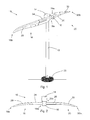
- a swept-blade partial-pitch two-bladed wind turbine is indicated generally at 10.
- the wind turbine 10 comprises a wind turbine tower 12, a nacelle 14 provided at the top of said tower 12, and a rotor hub 16 provided at said nacelle 14.
- First and second partial pitch rotor blades 18,20 are provided on opposite sides of said rotor hub 16.
- the tower 12 is shown provided on a wind turbine base 22, which may comprise any suitable wind turbine foundation. It will be understood that while the illustrated embodiment describes the use of the invention for an on-shore wind turbine, it will be understood that the invention may equally apply to wind turbines for use in an off-shore environment.
- the first and second partial pitch rotor blades 18,20 each comprise a blade body having a root end 18a,20a mounted to said rotor hub 16 and a distal tip end 18b,20b.
- the rotor blades 18,20 comprise respective inner blade sections 24,26 provided at said root ends 18a,20a, and respective outer blade sections 28,30 provided at said tip ends 18b,20b.
- the rotor blades 18,20 further comprise a pitch system (not shown) provided in each blade at the junction between the inner blade sections 24,26 and the outer blade sections 28,30.
- the pitch system is operable to pitch the outer blade sections 28,30 relative to the inner blade sections 24,26.
- the rotor blades 18 are shown unpitched (i.e. the outer blade sections 28,30 are pitched at a 0 degree pitch angle).
- the wind turbine blades 18,20 of the wind turbine 10 are forward-swept wind turbine blades, in that the blades are shaped such that the tip ends 18b,20b of the blades 18,20 point away from the wind turbine tower 12 (the tip ends of the blades are swept relative to the central longitudinal axis of the blades).
- Such forward-swept blades can be used in wind turbines to ensure that there is an adequate tip-to-tower ratio for operation of the wind turbine.
- the wind turbine 10 further comprises a controller (not shown) which is operable to implement a safety shutdown procedure in the event of extreme wind conditions.
- a controller may be a self-contained control device provided in the wind turbine structure, and/or may be communicatively coupled to a remote control station capable of managing the wind turbine operation from a remote location.
- an extreme wind condition it will be understood that this refers to very high wind speeds which can occur in the vicinity of the wind turbine tower, and for which said wind turbine towers and foundations must be designed to cope with adequately.
- the International Electrotechnical Commission (IEC) specifies extreme wind conditions as wind shear events, as well as peak wind speeds due to storms and rapid changes in wind speed direction.
- a wind turbine is expected to withstand extreme wind conditions of a specified wind speed to qualify as a particular class of IEC turbine (for example, an extreme wind of 70 m/s wind speed is currently specified for an IEC Class I turbine).
- a wind speed of greater than 20 metres per second may be regarded as an extreme wind condition.
- m/s a wind speed of greater than 20 metres per second
- such a turbine may need to be rated to withstand winds of up to 70 m/s.
- the design of the turbine structure may involve more use of reinforcement elements.
- an extreme wind condition may be at a higher level than in the case of a European-based turbine.
- a weather system comprising sustained winds of at least 33 metres per second (or 119 km/hour) is classified as a typhoon or hurricane.
- the wind turbine controller is operable to pitch the outer blade sections 28,30 in a particular manner that will allow the wind turbine blades 18,20 to align and stabilise in a substantially horizontal position.
- the outer blade sections 28,30 of the wind turbine blades 18,20 are pitched such that the tip ends 18b,20b of the blades 18,20 point in opposite directions along the path of rotation of the blades 18,20. This may be accomplished by pitching the first outer blade section 28 by a pitch angle of approximately +90 degrees, and pitching the second outer blade section 30 by a pitch angle of approximately -90 degrees (or +270 degrees).
- the movement of the centre of mass results in an unbalanced rotor assembly, which will stabilise to a position where the centre of mass of the rotor assembly is lowest, i.e. the substantially horizontal position indicated in Fig. 3 , where the tip ends 18b,20b of the blades 18,20 point in a downwards direction towards the surface level.
- a further consequence of the lowered centre of mass is that the rotor assembly is well balanced in the substantially horizontal position, and is more resistant to rotation of the blades 18,20 than a normal rotor assembly having a centre of mass at or adjacent the pivot point of the rotor assembly.
- the blades 18,20 are arranged to be substantially parallel to the ground level (or sea level) relative to the wind turbine, e.g. +/- 5 degrees. This is preferably in line with the wind direction at the turbine.
- the wind turbine 10 is operable to detect the current wind direction at the turbine, and to yaw the rotor assembly of the wind turbine (comprising the wind turbine blades 18,20 and the rotor hub 16, provided on the nacelle 14) such that the tip end 18b of one of the wind turbine blades 18 is pointed in the direction that the current wind is coming from, e.g.
- the wind turbine blades 18,20 are actively yawed using the turbine yaw mechanism (not shown) until the blades 18 are aligned with the wind direction, such that one of the tip ends 18b will point in a South Westerly direction, and the opposed tip end 20b points in a North Easterly direction.
- step of longitudinally aligning the blades 18,20 with the wind direction at the turbine 10 may be performed in parallel with, or before, the above described pitching step.
- the rotor assembly of the wind turbine may be yawed such that the plane of rotation of the wind turbine blades 18,20 is in parallel with the wind direction at the turbine 10.
- the pitching of the outer blade sections 28,30 to provide the rotor assembly in said horizontal alignment may provide an adjusted aerodynamic profile of the rotor assembly, said adjusted profile operable to passively align the wind turbine blades 18,20 with the oncoming wind direction at the wind turbine 10.
- the pitched swept blades may act similar to a wind vane, which will be moved by the force of the wind to point an end of the rotor assembly into the current wind direction.
- the surface area of the blades 18,20 presented to the wind is minimised (when compared with the situation when the wind may be acting on the surface along the entire longitudinal length of the blade).
- the load forces experienced by the wind turbine structure due to the extreme wind are also minimised. This leads to a reduction in the extreme loads experienced by the wind turbine 10.
- An advantage of such a reduction in extreme loads is that the construction requirements for the wind turbine structure may also be reduced, resulting in less manufacturing cost and effort.
- the wind turbine blades 18,20 are actively yawed to longitudinally align the plane of the rotational path of the blades 18,20 with the wind direction at the turbine 10, e.g. using the wind turbine yaw mechanism. As the blades 18,20 are actively yawed to point into the wind direction, this ensures that the blades 18,20 will be accurately aligned with the wind direction at the turbine 10, regardless of turbine size and/or blade balancing.
- the wind turbine 10 may comprise any suitable devices for determining wind speed, e.g. an anemometer, and wind direction, e.g. a wind vane provided on the wind turbine structure. Additionally or alternatively, the wind turbine 10 is operable to receive information regarding a forecasted wind direction for the turbine, and to yaw the wind turbine blades 18,20 to align with said forecasted wind direction, e.g. in anticipation of extreme wind speeds from the forecasted direction.
- the system may be relatively easily implemented in existing wind turbine control systems, which will normally comprise a controller (which may be local to the wind turbine site, or controlled from a remote control centre) operable to interface with the blade pitch systems, to provide a single control signal to the pitch systems to coordinate the pitching of the blades.
- the controller is operable to introduce an offset of +/- 180 degrees to the control signal sent to one of the pitch systems. Accordingly, while a first blade will be pitched to approximately +90 degrees, with the control signal for the first blade indicating a pitch angle for the pitch system of +90 degrees, the second blade will be pitched to approximately -90 (or +270) degrees, as the control signal transmitted by the controller will be -90/+270 degrees.
- This relatively simple modification of controller output can provide for ease of implementation of the method of the invention in existing wind turbine controller and pitch system configurations.
- the controller may be operable to adjust the weight distribution of the rotor assembly in order to stabilise the rotor assembly in a substantially horizontal arrangement.
- weights provided within the body of the wind turbine blades may be adjusted in position (e.g. moveable weights provided on a suitable adjustable pinion mechanism), or fluids may be pumped into chambers or cavities provided in the rotor assembly from a suitable reservoir or liquid source (e.g. the surrounding ocean in an off-shore turbine).
- a suitable reservoir or liquid source e.g. the surrounding ocean in an off-shore turbine.
- Such weight adjustment can act to increase the inertia of the rotor assembly and/or lower the centre of mass of the rotor assembly, and thereby make the rotor assembly more resistant to rotation from the stable horizontal equilibrium position.
- a moderate braking force may be applied in parallel with the above method to supplement the stabilisation of the wind turbine blades in a substantially horizontal position.
- an initial braking force may be applied to the wind turbine blades to slow the rotation of the blades to a speed at which the above described pitching of the safety shutdown procedure may be performed.
- the pitching of the wind turbine blades to lower the centre of mass of the rotor assembly may be performed once the rotor blades have been brought to a halt, preferably in a substantially horizontal position, e.g. by applying a braking mechanism to the rotor assembly and/or connected shaft.
- the braking force may comprise any suitable electrical and/or mechanical brakes, and/or the blades themselves may be initially pitched to a pitch angle operable to slow the rotation of the wind turbine blades.
- the positioning of the wind turbine blades in line with the wind direction means that the surface area of the rotor assembly exposed to the oncoming extreme winds is minimised, and the resultant extreme wind loads on the rotor assembly and wind turbine structure are reduced. This allows for a re-dimensioning of the components required for the particular wind turbine construction, resulting in a corresponding saving in wind turbine costs.
- the alignment of the pitched wind turbine blades to lower the centre of mass of the rotor assembly provides a stable configuration of the rotor assembly, as the assembly is more resistant to being rotated from said horizontal position.
Landscapes
- Engineering & Computer Science (AREA)
- Life Sciences & Earth Sciences (AREA)
- Sustainable Development (AREA)
- Sustainable Energy (AREA)
- Chemical & Material Sciences (AREA)
- Combustion & Propulsion (AREA)
- Mechanical Engineering (AREA)
- General Engineering & Computer Science (AREA)
- Physics & Mathematics (AREA)
- Fluid Mechanics (AREA)
- Wind Motors (AREA)
Applications Claiming Priority (1)
| Application Number | Priority Date | Filing Date | Title |
|---|---|---|---|
| DKPA201170248A DK177326B1 (en) | 2011-05-19 | 2011-05-19 | A Wind Turbine and Wind Turbine Blade |
Publications (2)
| Publication Number | Publication Date |
|---|---|
| EP2525085A2 true EP2525085A2 (de) | 2012-11-21 |
| EP2525085A3 EP2525085A3 (de) | 2014-05-21 |
Family
ID=46125222
Family Applications (1)
| Application Number | Title | Priority Date | Filing Date |
|---|---|---|---|
| EP12167465.9A Withdrawn EP2525085A3 (de) | 2011-05-19 | 2012-05-10 | Windturbine und Windturbinenschaufel |
Country Status (5)
| Country | Link |
|---|---|
| US (1) | US20120294715A1 (de) |
| EP (1) | EP2525085A3 (de) |
| CN (1) | CN102787969A (de) |
| CA (1) | CA2776216A1 (de) |
| DK (1) | DK177326B1 (de) |
Cited By (2)
| Publication number | Priority date | Publication date | Assignee | Title |
|---|---|---|---|---|
| CN103016276A (zh) * | 2012-12-07 | 2013-04-03 | 清华大学 | 用于大型风力发电机的两段式倾斜折叠叶片装置 |
| EP2910778A4 (de) * | 2012-12-19 | 2015-11-18 | Mitsubishi Heavy Ind Ltd | Windmühle und betriebsverfahren dafür |
Families Citing this family (11)
| Publication number | Priority date | Publication date | Assignee | Title |
|---|---|---|---|---|
| DK177422B1 (en) * | 2011-05-06 | 2013-04-22 | Envision Energy Denmark Aps | A Wind Turbine and Associated Control Method |
| DK177278B1 (en) * | 2011-05-19 | 2012-09-17 | Envision Energy Denmark Aps | A wind turbine and associated control method |
| CN103883466B (zh) * | 2014-02-24 | 2016-03-23 | 张效新 | 具有门扇形叶片及可伸缩风轮的水平轴风力发电机 |
| CN103883465B (zh) * | 2014-02-24 | 2016-03-23 | 张效新 | 具有船桨形叶片及鼓状可伸缩风轮的水平轴风力发电机 |
| DK178808B1 (en) * | 2014-12-12 | 2017-02-13 | Envision Energy Denmark Aps | Floating wind turbine structure with reduced tower height and method for optimising the weight thereof |
| CN108005847B (zh) * | 2016-11-02 | 2019-08-06 | 远景能源(江苏)有限公司 | 非发电运行时减小风力涡轮机载荷的方法 |
| DE102017000435A1 (de) * | 2017-01-19 | 2018-07-19 | Senvion Gmbh | Verfahren zum Drehen des Rotors einer Windenergieanlage |
| CN112424468B (zh) * | 2018-06-14 | 2023-08-22 | 维斯塔斯风力系统有限公司 | 具有用于停止的枢转转子叶片、线和释放机构的风力涡轮机 |
| CN108953052B (zh) * | 2018-06-27 | 2020-02-21 | 明阳智慧能源集团股份公司 | 一种降低风力发电机组停机工况下极端载荷的方法 |
| AU2018446413A1 (en) * | 2018-10-25 | 2021-05-27 | General Electric Renovables España, S.L. | Spar cap configuration for a jointed wind turbine blade |
| US20220397091A1 (en) * | 2019-11-07 | 2022-12-15 | Vestas Wind Systems A/S | Pivot angle control of blades of a wind turbine with hinged blades |
Citations (1)
| Publication number | Priority date | Publication date | Assignee | Title |
|---|---|---|---|---|
| EP0709571A2 (de) | 1994-10-25 | 1996-05-01 | AUTOFLUG ENERGIETECHNIK GmbH + CO. | Für eine lastarme Parkstellung eingerichtete Windkraftanlage |
Family Cites Families (3)
| Publication number | Priority date | Publication date | Assignee | Title |
|---|---|---|---|---|
| US4355955A (en) * | 1981-04-06 | 1982-10-26 | The Boeing Company | Wind turbine rotor speed control system |
| US5151610A (en) * | 1990-11-29 | 1992-09-29 | St Germain Jean | Wind machine with electric generators and secondary rotors located on rotating vertical blades |
| US6441507B1 (en) * | 2000-03-22 | 2002-08-27 | The Wind Turbine Company | Rotor pitch control method and apparatus for parking wind turbine |
-
2011
- 2011-05-19 DK DKPA201170248A patent/DK177326B1/en not_active IP Right Cessation
-
2012
- 2012-05-07 CA CA2776216A patent/CA2776216A1/en not_active Abandoned
- 2012-05-10 EP EP12167465.9A patent/EP2525085A3/de not_active Withdrawn
- 2012-05-16 US US13/472,933 patent/US20120294715A1/en not_active Abandoned
- 2012-05-18 CN CN2012101573251A patent/CN102787969A/zh active Pending
Patent Citations (1)
| Publication number | Priority date | Publication date | Assignee | Title |
|---|---|---|---|---|
| EP0709571A2 (de) | 1994-10-25 | 1996-05-01 | AUTOFLUG ENERGIETECHNIK GmbH + CO. | Für eine lastarme Parkstellung eingerichtete Windkraftanlage |
Cited By (3)
| Publication number | Priority date | Publication date | Assignee | Title |
|---|---|---|---|---|
| CN103016276A (zh) * | 2012-12-07 | 2013-04-03 | 清华大学 | 用于大型风力发电机的两段式倾斜折叠叶片装置 |
| CN103016276B (zh) * | 2012-12-07 | 2015-01-21 | 清华大学 | 用于大型风力发电机的两段式倾斜折叠叶片装置 |
| EP2910778A4 (de) * | 2012-12-19 | 2015-11-18 | Mitsubishi Heavy Ind Ltd | Windmühle und betriebsverfahren dafür |
Also Published As
| Publication number | Publication date |
|---|---|
| DK177326B1 (en) | 2013-01-07 |
| US20120294715A1 (en) | 2012-11-22 |
| EP2525085A3 (de) | 2014-05-21 |
| DK201170248A (en) | 2012-11-20 |
| CA2776216A1 (en) | 2012-11-19 |
| CN102787969A (zh) | 2012-11-21 |
Similar Documents
| Publication | Publication Date | Title |
|---|---|---|
| EP2525085A2 (de) | Windturbine und Windturbinenschaufel | |
| US9234502B2 (en) | Wind turbine and associated control method | |
| CN102777322B (zh) | 风力涡轮机和相关的控制方法 | |
| KR100609289B1 (ko) | 폭풍 시의 풍력 발전 터빈의 방위각 제어 방법 | |
| US9127644B2 (en) | Wind turbine and an associated control method | |
| US6441507B1 (en) | Rotor pitch control method and apparatus for parking wind turbine | |
| JP5806280B2 (ja) | 浮き基礎を持つ部分ピッチ風力タービン | |
| US9133824B2 (en) | Wind turbine and an associated yaw control method | |
| DK2264311T3 (en) | Wind turbine comprising an active flow control device on the rotor blade | |
| EP4426933B1 (de) | Verfahren zur reduzierung der blattklappenlasten in einer windturbine | |
| CN107002634B (zh) | 风能设备的设计 | |
| EP2686547B1 (de) | Leeläufer mit freiem giersystem | |
| EP2910778A1 (de) | Windmühle und betriebsverfahren dafür | |
| US8704391B2 (en) | Method of parking double-bladed rotor of wind power plant | |
| WO2021043381A1 (en) | A wind energy farm comprising wind turbines with hinged blades |
Legal Events
| Date | Code | Title | Description |
|---|---|---|---|
| PUAI | Public reference made under article 153(3) epc to a published international application that has entered the european phase |
Free format text: ORIGINAL CODE: 0009012 |
|
| AK | Designated contracting states |
Kind code of ref document: A2 Designated state(s): AL AT BE BG CH CY CZ DE DK EE ES FI FR GB GR HR HU IE IS IT LI LT LU LV MC MK MT NL NO PL PT RO RS SE SI SK SM TR |
|
| AX | Request for extension of the european patent |
Extension state: BA ME |
|
| PUAL | Search report despatched |
Free format text: ORIGINAL CODE: 0009013 |
|
| AK | Designated contracting states |
Kind code of ref document: A3 Designated state(s): AL AT BE BG CH CY CZ DE DK EE ES FI FR GB GR HR HU IE IS IT LI LT LU LV MC MK MT NL NO PL PT RO RS SE SI SK SM TR |
|
| AX | Request for extension of the european patent |
Extension state: BA ME |
|
| RIC1 | Information provided on ipc code assigned before grant |
Ipc: F03D 7/02 20060101AFI20140414BHEP |
|
| STAA | Information on the status of an ep patent application or granted ep patent |
Free format text: STATUS: THE APPLICATION HAS BEEN WITHDRAWN |
|
| 18W | Application withdrawn |
Effective date: 20140717 |