EP2525106B1 - Vorrichtung zur Verbindung von zwei Platten eines Möbelstücks miteinander - Google Patents
Vorrichtung zur Verbindung von zwei Platten eines Möbelstücks miteinander Download PDFInfo
- Publication number
- EP2525106B1 EP2525106B1 EP12168268.6A EP12168268A EP2525106B1 EP 2525106 B1 EP2525106 B1 EP 2525106B1 EP 12168268 A EP12168268 A EP 12168268A EP 2525106 B1 EP2525106 B1 EP 2525106B1
- Authority
- EP
- European Patent Office
- Prior art keywords
- panels
- screw
- piece
- furniture
- tensor
- Prior art date
- Legal status (The legal status is an assumption and is not a legal conclusion. Google has not performed a legal analysis and makes no representation as to the accuracy of the status listed.)
- Not-in-force
Links
Images


Classifications
-
- F—MECHANICAL ENGINEERING; LIGHTING; HEATING; WEAPONS; BLASTING
- F16—ENGINEERING ELEMENTS AND UNITS; GENERAL MEASURES FOR PRODUCING AND MAINTAINING EFFECTIVE FUNCTIONING OF MACHINES OR INSTALLATIONS; THERMAL INSULATION IN GENERAL
- F16B—DEVICES FOR FASTENING OR SECURING CONSTRUCTIONAL ELEMENTS OR MACHINE PARTS TOGETHER, e.g. NAILS, BOLTS, CIRCLIPS, CLAMPS, CLIPS OR WEDGES; JOINTS OR JOINTING
- F16B12/00—Jointing of furniture or the like, e.g. hidden from exterior
- F16B12/10—Jointing of furniture or the like, e.g. hidden from exterior using pegs, bolts, tenons, clamps, clips, or the like
- F16B12/12—Jointing of furniture or the like, e.g. hidden from exterior using pegs, bolts, tenons, clamps, clips, or the like for non-metal furniture parts, e.g. made of wood, of plastics
- F16B12/20—Jointing of furniture or the like, e.g. hidden from exterior using pegs, bolts, tenons, clamps, clips, or the like for non-metal furniture parts, e.g. made of wood, of plastics using clamps, clips, wedges, sliding bolts, or the like
- F16B12/2009—Jointing of furniture or the like, e.g. hidden from exterior using pegs, bolts, tenons, clamps, clips, or the like for non-metal furniture parts, e.g. made of wood, of plastics using clamps, clips, wedges, sliding bolts, or the like actuated by rotary motion
- F16B12/2054—Jointing of furniture or the like, e.g. hidden from exterior using pegs, bolts, tenons, clamps, clips, or the like for non-metal furniture parts, e.g. made of wood, of plastics using clamps, clips, wedges, sliding bolts, or the like actuated by rotary motion with engaging screw threads as securing means for limiting movement
- F16B12/2063—Jointing of furniture or the like, e.g. hidden from exterior using pegs, bolts, tenons, clamps, clips, or the like for non-metal furniture parts, e.g. made of wood, of plastics using clamps, clips, wedges, sliding bolts, or the like actuated by rotary motion with engaging screw threads as securing means for limiting movement with engaging screw threads as tightening means
Definitions
- This invention concerns a device to connect by means of pressure, but with the possibility of disassembly, panels of furniture or similar, such that, in the connection, the edge of one of them is applied to one facet of the other panel.
- connection systems of a general composition known from prior art consisting of a first panel having a junction box on one of its larger facets that is open to an adjacent edge of the same, which junction contains a cylindrical tensile support consisting of two symmetric, semi-cylindrical parts on the diametrical plane perpendicular to that edge and having a tensile axis that is also perpendicular to the edge, and that is actuated rotationally by a gear assembly, and a second panel of which the facet connecting with the first panel has a blind or through hole that may be aligned with the tensile access, and may incorporate (or not) a plug or a nut within it.
- connection must not leave gaps between the panels connected; otherwise, the aesthetic effect would be negative both in terms of appearance and in terms of giving an impression of low quality to the furniture as a whole; however, especially the fact that a connection with an attachment defect adversely affects the strength and structural stability of the furniture, particularly when the same piece of furniture has connections with defects of different dimensions.
- devices are known such as that of the German utility model DE7814325U1 .
- This model includes various solutions involving sets of cogwheels to actuate the forward/backward motion of a "tensor screw" belonging to a mechanism within the casing built into one of the panels to be connected, and which is the one that will form the connection by screwing into a blind hole of the other of the two panels to be connected, whether directly or by means of a fitting previously built into this second panel.
- the device installed in the aforementioned first panel must also not allow the point of the tensor screw to protrude beyond the edge of this first panel when the furniture has not yet been installed. Otherwise, if the devices are installed in the first panel before beginning assembly, packaging and shipping become difficult, apart from the risk of causing physical damage to the assembler and/or other parts of the furniture during assembly; the alternative would be to carry the devices in a separate package. Additionally, if we imagine a shelving unit consisting of various shelves between two panels like the first panel, if the point of the screw cannot be concealed completely in the casing of the device, in order to change the height of a shelf, one of the first panels must be completely released.
- the invention proposes a connecting device for systems having the general composition described in the subject-matter of the invention, consisting of a tensile support with a serrated washer, axially fixated, having peripheral radial external teeth corresponding in shape to the existing gear recesses in one opposite face of the drive crown, the opposite face of which has an actuator groove;
- the tensor axis is a tensor screw with a threaded point connected to a central non-cylindrical body and a head, and at least one threaded area of the tensor screw is in contact with an inner wall of the tensile support;
- the serrated washer has a non-cylindrical central hole corresponding in shape to the section of the non-cylindrical central body of the tensor screw, forming a keyed insertion.
- the dimension of the operative range of the tensor screw between its extreme retracted position within the tensile support and its extreme extended position is preferably less than the depth of the blind or through-hole or the length of the internal threading of the plug.
- the operative range of the tensor screw is limited by the serrated washer or an internal part of the tensile support.
- One variant consists of at least one internal wall (3a) being a continuous cylindrical wall, with threading reciprocal to that of the head (5b) of the tensor screw.
- the composition contemplated makes possible a sequential operation to make the connection, ensuring perfect connection of both panels.
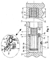
- the attached drawings show a preferred embodiment of the invention, relating to a device to connect two panels of a piece of furniture, having a known, consistent composition ( fig. 1 ) in a first panel (1), one of the larger facets of which has a junction box (1a) with a lateral opening (1b) open to an edge adjacent to it, the junction box (1a) where a tensile support(3) is fitted, usually cylindrical and consisting of two semi-cylindrical parts, symmetrical on the diametrical plane perpendicular to that edge and having a tensile axis that is also perpendicular to this edge, actuated for turning by means of a gear assembly, and a second panel (2) with a facet connecting to the first panel (1) that has a blind or through hole (2a) that can be aligned with the tensile axis and usually having (or not having) a plug (4) or a nut contained in the same.
- Fig. 1 - 4 clearly shows the invention, consisting of a tensile support (3) with a serrated washer (6), axially fixated, having peripheral radial external teeth (6a) corresponding in shape to the existing gear recesses (7a) in one opposite face of the drive crown (7), the opposite face of which has an actuator groove (7b);
- the tensor axis is a tensor screw (5) with a threaded point (5a) connected to a central non-cylindrical body (5c) and a head (5b), and at least one threaded area (5a-5b) of the tensor screw (5) is in contact with an inner wall (3a) of the tensile support (3);
- the serrated washer (6) has a non-cylindrical central hole (6c) corresponding in shape to the section of the non-cylindrical central body (5c) of the tensor screw (5), forming a keyed insertion.
- the dimension of the operative range (9) of the tensor screw (5) between its extreme retracted position within the tensile support (3) and its extreme extended position, is preferably less than the depth (10) of the blind or through-hole (2a) or the length of the internal threading (11) of the plug (4).
- the operative range (9) of the tensor screw (5) is limited by the serrated washer (6) or an internal part (3a) of the tensile support (3). In fig.
- fig. 1 shows the characteristic elevations of the invention, related to the operative range (9) of the tensor screw (5), the depth (10) of the blind hole (2a), and the length of the internal threading (11) of the plug (4), which, in this case, is positioned in the blind hole (2a).
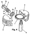
- FIG. 3 and 4 show in detail the configuration of the components of the device; in each case, the tensor screw (5) and the serrated washer (6) are shown according to differing variants amongst those falling within the invention, some of which are shown in fig. 5 - 12 .
- At least one internal wall (3a) is a continuous cylindrical wall and has cut into it a reciprocal threading to that of the head (5b) of the tensor screw (5), which is the option used in fig. 1 and 2 .
- FIG. 5 and 6 show the variant elected for fig. 1 - 3 , where the central body (5c) has a polygonal section reciprocal to the central non-cylindrical hole (6c) in the serrated washer (6), an octagonal polygonal section.
- Fig. 7 and 8 show the variant elected for fig. 4 , consisting of the central body (5c), which has at least one keyway (5e), which is reciprocal to at least one key (6b), protruding into the non-cylindrical central hole (6c) in the serrated washer (6).
- Fig. 5 and 6 show the variant elected for fig. 1 - 3 , where the central body (5c) has a polygonal section reciprocal to the central non-cylindrical hole (6c) in the serrated washer (6), an octagonal polygonal section.
- Fig. 7 and 8 show the variant elected for fig. 4 , consisting of the central body (5c), which has at least one keyway (5e), which
- FIG. 9 and 10 show a variant in which the central body (5c) has a mixed section with curved and rectilinear parts, which is reciprocal to the central non-cylindrical hole (6c) in the serrated washer (6).
- Fig. 13 and 14 show a variant in which the head (5b) of the tensor screw (5) is not threaded.
- Another possible variant, shown in fig. 15 and 16 consists of the tensor screw (5) being threaded over its entire length, and having at least one keyway (5e).
- the threaded end (5a) of the screw (5) has a self-threading filleting for wood, an option shown in fig. 11 and 12 .
- the rear protrusion (5d) of the central body (5c), applied to the serrated washer (6) or an internal part of the tensile support (3), is the frontal aspect of the threaded head (5b), as shown in all drawings.
- the scope of the invention includes an option in which the peripheral radial teeth (6a) and the engaging recesses (7a) are formed reciprocally as a conical gear assembly.
- the operation of the device is shown by means of fig. 17 - 20 , explaining the sequence of actions required to connect the first panel (1) and the second panel (2).
- it consists of a first operation in which ( fig. 15 ) the first panel (1) and the second panel (2) are positioned in the relative position in which they will be connected, turning the drive crown (7), turning the serrated washer (6) with the tool (8), and, with it, the central body (5c), i.e., the tensor screw (5), which, due to the threading of its threaded head (5b) on the internal wall (3a), advances ( fig. 16 ) until it begins to engage ( fig.
- the drawings also show that, in its retracted position, the tensor screw (5) is totally concealed in the tensile support (3), making it possible for it to be installed in the first panel until the assembly point, facilitating packaging and shipping, as well as handling without risk of damage to persons or materials. Additionally, once a shelving unit has been built, a shelf can be repositioned by merely disassembling that shelf and replacing it in a new position.
Landscapes
- Engineering & Computer Science (AREA)
- General Engineering & Computer Science (AREA)
- Mechanical Engineering (AREA)
- Connection Of Plates (AREA)
- Furniture Connections (AREA)
- Mutual Connection Of Rods And Tubes (AREA)
- Pivots And Pivotal Connections (AREA)
Claims (12)
- Vorrichtung zur Verbindung von zwei Platten eines Möbelstücks, das eine erste Platte (1) mit einem Verbindungsraum (1a), der eine seitliche Öffnung (1b) an einer ihrer größeren Seitenflächen aufweist, die zu einem dazu benachbarten Rand hin offen ist, wobei der Verbindungsraum (1a) einen gewöhnlich zylindrischen Zughalter (3) enthält, der aus zwei halbzylindrischen Teilen besteht, die entlang der Durchmesserebene senkrecht zu dem Rand symmetrisch sind, und eine Zugachse aufweist, die ebenfalls senkrecht zu diesem Rand verläuft und die mittels einer Eingriffanordnung gedreht wird, und eine zweite Platte (2) aufweist, die eine Blind- oder Durchgangsbohrung (2a) an der Seitenfläche aufweist, die mit der ersten Platte (1) verbunden wird, die nach der Zugachse ausgerichtet sein kann und gewöhnlich einen Einsatz (4) oder eine Mutter enthält (oder nicht enthält), dadurch gekennzeichnet, dass der Zughalter (3) eine axial fixierte gezahnte Scheibe (6) enthält, die äußere, am Rand befindliche Radialzähne (6a) aufweist, deren Form den Eingriffvertiefungen (7a) an einer Seitenfläche entspricht, die der Drehscheibe (7) zugewandt ist, die eine Betätigungselementnut auf ihrer gegenüberliegenden Seitenfläche (7b) aufweist; die Zugachse eine Spannschraube (5) mit einem Gewindeende (5a) ist, das mit einem nicht zylindrischen mittigen Körper (5c) und einem Kopf (5b) verbunden ist, und mindestens ein mit einem Gewinde versehener Bereich (5a-5b) der Spannschraube (5) in Berührung mit einer Innenwand (3a) des Zughalters (3); die gezahnte Scheibe (6) eine in der Form dem Querschnitt des nicht zylindrischen mittigen Körpers (5c) der Zugschraube (5) entsprechende nicht zylindrische mittige Bohrung (6c) aufweist, die ein Naseneinsatzteil bildet.
- Vorrichtung zur Verbindung von zwei Platten eines Möbelstücks nach Anspruch 1, dadurch gekennzeichnet, dass die Abmessung des wirksamen Bereichs (9) der Spannschraube (5) zwischen ihrer äußersten in den Zughalter (3) zurückgezogenen Stellung und ihrer äußersten ausgestreckten Stellung vorzugsweise geringer ist als die Tiefe (10) der Blind- oder Durchgangsbohrung (2a) oder die Länge des Innengewindes (11) des Einsatzes (4).
- Vorrichtung zur Verbindung von zwei Platten eines Möbelstücks nach Anspruch 1, dadurch gekennzeichnet, dass der wirksame Bereich (9) der Spannschraube (5) durch die gezahnte Scheibe (6) oder einen inneren Teil (3a) des Zughalters (3) eingeschränkt ist.
- Vorrichtung zur Verbindung von zwei Platten eines Möbelstücks nach Anspruch 1, dadurch gekennzeichnet, dass die mindestens eine Innenwand (3a) eine durchgängige zylindrische Wand mit einem Gewinde ist, das auf das des Kopfs (5b) der Spannschraube (5) abgestimmt ist.
- Vorrichtung zur Verbindung von zwei Platten eines Möbelstücks nach Anspruch 1, dadurch gekennzeichnet, dass der mittige Körper (5c) einen vieleckigen Querschnitt abgestimmt auf die nicht zylindrische mittige Bohrung (6c) der gezahnten Scheibe (6) aufweist.
- Vorrichtung zur Verbindung von zwei Platten eines Möbelstücks nach Anspruch 1, dadurch gekennzeichnet, dass der mittige Körper (5c) mindestens eine Nasennut (5e) aufweist, die auf mindestens eine Nase (6b) abgestimmt ist, die in die nicht zylindrische mittige Bohrung (6c) der gezahnte Scheibe (6) ragt.
- Vorrichtung zur Verbindung von zwei Platten eines Möbelstücks nach Anspruch 1, dadurch gekennzeichnet, dass der mittige Körper (5c) einen gemischten Querschnitt mit gekrümmten und geradlinigen Teilen aufweist, der auf die nicht zylindrische mittige Bohrung (6c) der gezahnten Scheibe (6) abgestimmt ist.
- Vorrichtung zur Verbindung von zwei Platten eines Möbelstücks nach Anspruch 1, dadurch gekennzeichnet, dass das Gewindeende (5a) selbstbohrende Kehlflächen für Holz aufweist.
- Vorrichtung zur Verbindung von zwei Platten eines Möbelstücks nach Anspruch 1, dadurch gekennzeichnet, dass die hintere Vorwölbung (5d) des mittigen Körpers (5c), die an die gezahnte Scheibe (6) oder einen inneren Teil des Zughalters (3) angelegt wird, die vordere Seitenfläche des Kopfs (5b) ist.
- Vorrichtung zur Verbindung von zwei Platten eines Möbelstücks nach Anspruch 1, dadurch gekennzeichnet, dass die am Rand befindlichen Radialzähne (6a) und die Eingriffvertiefungen (7a) abgestimmt aufeinander in Form eines Kegelradgetriebes geschnitten sind.
- Vorrichtung zur Verbindung von zwei Platten eines Möbelstücks nach Anspruch 1, dadurch gekennzeichnet, dass die Spannschraube (5) über ihre gesamte Länge mit einem Gewinde versehen ist und mindestens eine Nasennut (5e) aufweist.
- Vorrichtung zur Verbindung von zwei Platten eines Möbelstücks nach Anspruch 1, dadurch gekennzeichnet, dass der Kopf (5b) der Spannschraube (5) nicht mit einem Gewinde versehen ist.
Applications Claiming Priority (1)
| Application Number | Priority Date | Filing Date | Title |
|---|---|---|---|
| ES201130813A ES2400583B1 (es) | 2011-05-19 | 2011-05-19 | Dispositivo de unión entre dos paneles de un mueble |
Publications (3)
| Publication Number | Publication Date |
|---|---|
| EP2525106A2 EP2525106A2 (de) | 2012-11-21 |
| EP2525106A3 EP2525106A3 (de) | 2014-12-17 |
| EP2525106B1 true EP2525106B1 (de) | 2016-03-09 |
Family
ID=46147316
Family Applications (1)
| Application Number | Title | Priority Date | Filing Date |
|---|---|---|---|
| EP12168268.6A Not-in-force EP2525106B1 (de) | 2011-05-19 | 2012-05-16 | Vorrichtung zur Verbindung von zwei Platten eines Möbelstücks miteinander |
Country Status (2)
| Country | Link |
|---|---|
| EP (1) | EP2525106B1 (de) |
| ES (2) | ES2400583B1 (de) |
Families Citing this family (1)
| Publication number | Priority date | Publication date | Assignee | Title |
|---|---|---|---|---|
| DE102014101158B4 (de) * | 2014-01-30 | 2026-03-26 | Lamello Ag | Verbindungsmittel und Verfahren zum Verbinden zweier Bauteile |
Family Cites Families (9)
| Publication number | Priority date | Publication date | Assignee | Title |
|---|---|---|---|---|
| US3264019A (en) * | 1964-01-06 | 1966-08-02 | Dow Chemical Co | Joining device for structures |
| DE7814325U1 (de) | 1977-05-13 | 1978-11-23 | Julius Blum Gmbh, Hoechst (Oesterreich) | Möbelverbindungsbeschlag |
| KR960001737B1 (ko) * | 1993-03-23 | 1996-02-03 | 김경주 | 조립식 하우스의 패널 |
| IT1273427B (it) * | 1994-04-08 | 1997-07-08 | Antonio Giovannetti | Dispositivo di giunzione di pannelli, ad avvitamento |
| US5743670A (en) * | 1995-10-02 | 1998-04-28 | Ader; Thompson G. | Structural fastener |
| ITMI20030799A1 (it) * | 2003-04-17 | 2004-10-18 | Mauri Flli Srl | Dispositivo per la giunzione di due parti tra loro disposte a 90°. |
| ITPN20050035U1 (it) * | 2005-12-02 | 2007-06-03 | Livenza Ferramenta Srl | Giunzione per il collegamento amovibile di due elementi strutturali di mobile attestati ortogonalmente. |
| AU2005244596C1 (en) * | 2005-12-19 | 2008-04-17 | Milan Pilja | Integrated joiner |
| WO2008076089A2 (en) * | 2006-12-19 | 2008-06-26 | Maru Mimarlik Insaat Sanayi Ve Ticaret Limited Sirketi | Fastening system with gears for modular construction elements |
-
2011
- 2011-05-19 ES ES201130813A patent/ES2400583B1/es not_active Expired - Fee Related
-
2012
- 2012-05-16 EP EP12168268.6A patent/EP2525106B1/de not_active Not-in-force
- 2012-05-16 ES ES12168268.6T patent/ES2565808T3/es active Active
Also Published As
| Publication number | Publication date |
|---|---|
| ES2400583R1 (es) | 2013-06-19 |
| ES2400583A2 (es) | 2013-04-10 |
| ES2400583B1 (es) | 2014-03-04 |
| ES2565808T3 (es) | 2016-04-07 |
| EP2525106A2 (de) | 2012-11-21 |
| EP2525106A3 (de) | 2014-12-17 |
Similar Documents
| Publication | Publication Date | Title |
|---|---|---|
| JP6889667B2 (ja) | 家具および家財アイテムのパーツのための、視認性が最小限の接合デバイス | |
| US5192145A (en) | Cross coupling for bars | |
| US9140289B2 (en) | Fixing device for a furniture fitting | |
| US20030007845A1 (en) | Screw for screwing into a material of low strength | |
| US20150377269A1 (en) | Securing device for a furniture fitting | |
| CA2996745C (en) | Joining device with wide accessibility for parts of furniture and furnishing items | |
| EP3910204B1 (de) | Möbeln und anderen einrichtungsgegenständen mit kompaktem verbindungsstück zur verbindung einer ersten und einer zweiten platte | |
| US9587662B2 (en) | Threaded fastener hole repair apparatus | |
| US9080586B2 (en) | D-type screwing assembly for furniture | |
| BRPI0609538A2 (pt) | prendedor para conectar componentes e conjuntos que concretizam o mesmo | |
| EP3426935B1 (de) | Zylinder für zylinderverbindung für teile eines möbels und möbelstücke | |
| JP2018529892A5 (ja) | 特に家具の壁にシェルフを結合するための結合装置 | |
| CN1395644A (zh) | 部件连接装置 | |
| DE102015219778B4 (de) | Möbelteilverbindungsanordnung | |
| EP2525106B1 (de) | Vorrichtung zur Verbindung von zwei Platten eines Möbelstücks miteinander | |
| US9297399B2 (en) | Bracket for securing a structural member | |
| US20210102570A1 (en) | Wood screw | |
| DE16713162T1 (de) | Männliches anti-falsch-faden-befestigungselement | |
| DE102013107034B3 (de) | Profilrohrverbindung als Bestandteil von Möbel-Gestellen | |
| WO2020053234A1 (en) | Dowel fasteners | |
| KR100846180B1 (ko) | 측벽 연결이 가능한 프레임 연결구조 | |
| EP2453143A2 (de) | Abscherbares Verbindungselement | |
| TWM547609U (zh) | 防鬆脫螺栓組件 | |
| KR101604979B1 (ko) | 셀프 태핑 나사 | |
| EP2565470A2 (de) | Dübel |
Legal Events
| Date | Code | Title | Description |
|---|---|---|---|
| PUAI | Public reference made under article 153(3) epc to a published international application that has entered the european phase |
Free format text: ORIGINAL CODE: 0009012 |
|
| AK | Designated contracting states |
Kind code of ref document: A2 Designated state(s): AL AT BE BG CH CY CZ DE DK EE ES FI FR GB GR HR HU IE IS IT LI LT LU LV MC MK MT NL NO PL PT RO RS SE SI SK SM TR |
|
| AX | Request for extension of the european patent |
Extension state: BA ME |
|
| PUAL | Search report despatched |
Free format text: ORIGINAL CODE: 0009013 |
|
| RIC1 | Information provided on ipc code assigned before grant |
Ipc: F16B 12/20 20060101AFI20141106BHEP |
|
| AK | Designated contracting states |
Kind code of ref document: A3 Designated state(s): AL AT BE BG CH CY CZ DE DK EE ES FI FR GB GR HR HU IE IS IT LI LT LU LV MC MK MT NL NO PL PT RO RS SE SI SK SM TR |
|
| AX | Request for extension of the european patent |
Extension state: BA ME |
|
| 17P | Request for examination filed |
Effective date: 20150410 |
|
| RBV | Designated contracting states (corrected) |
Designated state(s): AL AT BE BG CH CY CZ DE DK EE ES FI FR GB GR HR HU IE IS IT LI LT LU LV MC MK MT NL NO PL PT RO RS SE SI SK SM TR |
|
| GRAP | Despatch of communication of intention to grant a patent |
Free format text: ORIGINAL CODE: EPIDOSNIGR1 |
|
| INTG | Intention to grant announced |
Effective date: 20150828 |
|
| GRAS | Grant fee paid |
Free format text: ORIGINAL CODE: EPIDOSNIGR3 |
|
| GRAA | (expected) grant |
Free format text: ORIGINAL CODE: 0009210 |
|
| AK | Designated contracting states |
Kind code of ref document: B1 Designated state(s): AL AT BE BG CH CY CZ DE DK EE ES FI FR GB GR HR HU IE IS IT LI LT LU LV MC MK MT NL NO PL PT RO RS SE SI SK SM TR |
|
| REG | Reference to a national code |
Ref country code: GB Ref legal event code: FG4D |
|
| REG | Reference to a national code |
Ref country code: AT Ref legal event code: REF Ref document number: 779757 Country of ref document: AT Kind code of ref document: T Effective date: 20160315 Ref country code: CH Ref legal event code: EP |
|
| REG | Reference to a national code |
Ref country code: IE Ref legal event code: FG4D |
|
| REG | Reference to a national code |
Ref country code: ES Ref legal event code: FG2A Ref document number: 2565808 Country of ref document: ES Kind code of ref document: T3 Effective date: 20160407 |
|
| REG | Reference to a national code |
Ref country code: DE Ref legal event code: R096 Ref document number: 602012015345 Country of ref document: DE |
|
| REG | Reference to a national code |
Ref country code: FR Ref legal event code: PLFP Year of fee payment: 5 |
|
| REG | Reference to a national code |
Ref country code: LT Ref legal event code: MG4D |
|
| REG | Reference to a national code |
Ref country code: NL Ref legal event code: MP Effective date: 20160309 |
|
| PG25 | Lapsed in a contracting state [announced via postgrant information from national office to epo] |
Ref country code: NO Free format text: LAPSE BECAUSE OF FAILURE TO SUBMIT A TRANSLATION OF THE DESCRIPTION OR TO PAY THE FEE WITHIN THE PRESCRIBED TIME-LIMIT Effective date: 20160609 Ref country code: HR Free format text: LAPSE BECAUSE OF FAILURE TO SUBMIT A TRANSLATION OF THE DESCRIPTION OR TO PAY THE FEE WITHIN THE PRESCRIBED TIME-LIMIT Effective date: 20160309 Ref country code: GR Free format text: LAPSE BECAUSE OF FAILURE TO SUBMIT A TRANSLATION OF THE DESCRIPTION OR TO PAY THE FEE WITHIN THE PRESCRIBED TIME-LIMIT Effective date: 20160610 Ref country code: FI Free format text: LAPSE BECAUSE OF FAILURE TO SUBMIT A TRANSLATION OF THE DESCRIPTION OR TO PAY THE FEE WITHIN THE PRESCRIBED TIME-LIMIT Effective date: 20160309 |
|
| REG | Reference to a national code |
Ref country code: AT Ref legal event code: MK05 Ref document number: 779757 Country of ref document: AT Kind code of ref document: T Effective date: 20160309 |
|
| PG25 | Lapsed in a contracting state [announced via postgrant information from national office to epo] |
Ref country code: LV Free format text: LAPSE BECAUSE OF FAILURE TO SUBMIT A TRANSLATION OF THE DESCRIPTION OR TO PAY THE FEE WITHIN THE PRESCRIBED TIME-LIMIT Effective date: 20160309 Ref country code: RS Free format text: LAPSE BECAUSE OF FAILURE TO SUBMIT A TRANSLATION OF THE DESCRIPTION OR TO PAY THE FEE WITHIN THE PRESCRIBED TIME-LIMIT Effective date: 20160309 Ref country code: LT Free format text: LAPSE BECAUSE OF FAILURE TO SUBMIT A TRANSLATION OF THE DESCRIPTION OR TO PAY THE FEE WITHIN THE PRESCRIBED TIME-LIMIT Effective date: 20160309 Ref country code: PL Free format text: LAPSE BECAUSE OF FAILURE TO SUBMIT A TRANSLATION OF THE DESCRIPTION OR TO PAY THE FEE WITHIN THE PRESCRIBED TIME-LIMIT Effective date: 20160309 Ref country code: BE Free format text: LAPSE BECAUSE OF NON-PAYMENT OF DUE FEES Effective date: 20160531 Ref country code: SE Free format text: LAPSE BECAUSE OF FAILURE TO SUBMIT A TRANSLATION OF THE DESCRIPTION OR TO PAY THE FEE WITHIN THE PRESCRIBED TIME-LIMIT Effective date: 20160309 Ref country code: NL Free format text: LAPSE BECAUSE OF FAILURE TO SUBMIT A TRANSLATION OF THE DESCRIPTION OR TO PAY THE FEE WITHIN THE PRESCRIBED TIME-LIMIT Effective date: 20160309 |
|
| PG25 | Lapsed in a contracting state [announced via postgrant information from national office to epo] |
Ref country code: EE Free format text: LAPSE BECAUSE OF FAILURE TO SUBMIT A TRANSLATION OF THE DESCRIPTION OR TO PAY THE FEE WITHIN THE PRESCRIBED TIME-LIMIT Effective date: 20160309 Ref country code: IS Free format text: LAPSE BECAUSE OF FAILURE TO SUBMIT A TRANSLATION OF THE DESCRIPTION OR TO PAY THE FEE WITHIN THE PRESCRIBED TIME-LIMIT Effective date: 20160709 |
|
| PG25 | Lapsed in a contracting state [announced via postgrant information from national office to epo] |
Ref country code: PT Free format text: LAPSE BECAUSE OF FAILURE TO SUBMIT A TRANSLATION OF THE DESCRIPTION OR TO PAY THE FEE WITHIN THE PRESCRIBED TIME-LIMIT Effective date: 20160711 Ref country code: AT Free format text: LAPSE BECAUSE OF FAILURE TO SUBMIT A TRANSLATION OF THE DESCRIPTION OR TO PAY THE FEE WITHIN THE PRESCRIBED TIME-LIMIT Effective date: 20160309 Ref country code: SM Free format text: LAPSE BECAUSE OF FAILURE TO SUBMIT A TRANSLATION OF THE DESCRIPTION OR TO PAY THE FEE WITHIN THE PRESCRIBED TIME-LIMIT Effective date: 20160309 Ref country code: CZ Free format text: LAPSE BECAUSE OF FAILURE TO SUBMIT A TRANSLATION OF THE DESCRIPTION OR TO PAY THE FEE WITHIN THE PRESCRIBED TIME-LIMIT Effective date: 20160309 Ref country code: RO Free format text: LAPSE BECAUSE OF FAILURE TO SUBMIT A TRANSLATION OF THE DESCRIPTION OR TO PAY THE FEE WITHIN THE PRESCRIBED TIME-LIMIT Effective date: 20160309 Ref country code: SK Free format text: LAPSE BECAUSE OF FAILURE TO SUBMIT A TRANSLATION OF THE DESCRIPTION OR TO PAY THE FEE WITHIN THE PRESCRIBED TIME-LIMIT Effective date: 20160309 |
|
| REG | Reference to a national code |
Ref country code: DE Ref legal event code: R097 Ref document number: 602012015345 Country of ref document: DE |
|
| PG25 | Lapsed in a contracting state [announced via postgrant information from national office to epo] |
Ref country code: LU Free format text: LAPSE BECAUSE OF FAILURE TO SUBMIT A TRANSLATION OF THE DESCRIPTION OR TO PAY THE FEE WITHIN THE PRESCRIBED TIME-LIMIT Effective date: 20160516 Ref country code: BE Free format text: LAPSE BECAUSE OF FAILURE TO SUBMIT A TRANSLATION OF THE DESCRIPTION OR TO PAY THE FEE WITHIN THE PRESCRIBED TIME-LIMIT Effective date: 20160309 |
|
| REG | Reference to a national code |
Ref country code: CH Ref legal event code: PL |
|
| PLBE | No opposition filed within time limit |
Free format text: ORIGINAL CODE: 0009261 |
|
| STAA | Information on the status of an ep patent application or granted ep patent |
Free format text: STATUS: NO OPPOSITION FILED WITHIN TIME LIMIT |
|
| PG25 | Lapsed in a contracting state [announced via postgrant information from national office to epo] |
Ref country code: CH Free format text: LAPSE BECAUSE OF NON-PAYMENT OF DUE FEES Effective date: 20160531 Ref country code: LI Free format text: LAPSE BECAUSE OF NON-PAYMENT OF DUE FEES Effective date: 20160531 Ref country code: DK Free format text: LAPSE BECAUSE OF FAILURE TO SUBMIT A TRANSLATION OF THE DESCRIPTION OR TO PAY THE FEE WITHIN THE PRESCRIBED TIME-LIMIT Effective date: 20160309 |
|
| 26N | No opposition filed |
Effective date: 20161212 |
|
| REG | Reference to a national code |
Ref country code: IE Ref legal event code: MM4A |
|
| PG25 | Lapsed in a contracting state [announced via postgrant information from national office to epo] |
Ref country code: BG Free format text: LAPSE BECAUSE OF FAILURE TO SUBMIT A TRANSLATION OF THE DESCRIPTION OR TO PAY THE FEE WITHIN THE PRESCRIBED TIME-LIMIT Effective date: 20160609 |
|
| REG | Reference to a national code |
Ref country code: FR Ref legal event code: PLFP Year of fee payment: 6 |
|
| PG25 | Lapsed in a contracting state [announced via postgrant information from national office to epo] |
Ref country code: SI Free format text: LAPSE BECAUSE OF FAILURE TO SUBMIT A TRANSLATION OF THE DESCRIPTION OR TO PAY THE FEE WITHIN THE PRESCRIBED TIME-LIMIT Effective date: 20160309 Ref country code: IE Free format text: LAPSE BECAUSE OF NON-PAYMENT OF DUE FEES Effective date: 20160516 |
|
| REG | Reference to a national code |
Ref country code: FR Ref legal event code: PLFP Year of fee payment: 7 |
|
| PG25 | Lapsed in a contracting state [announced via postgrant information from national office to epo] |
Ref country code: CY Free format text: LAPSE BECAUSE OF FAILURE TO SUBMIT A TRANSLATION OF THE DESCRIPTION OR TO PAY THE FEE WITHIN THE PRESCRIBED TIME-LIMIT Effective date: 20160309 Ref country code: HU Free format text: LAPSE BECAUSE OF FAILURE TO SUBMIT A TRANSLATION OF THE DESCRIPTION OR TO PAY THE FEE WITHIN THE PRESCRIBED TIME-LIMIT; INVALID AB INITIO Effective date: 20120516 |
|
| PG25 | Lapsed in a contracting state [announced via postgrant information from national office to epo] |
Ref country code: MC Free format text: LAPSE BECAUSE OF FAILURE TO SUBMIT A TRANSLATION OF THE DESCRIPTION OR TO PAY THE FEE WITHIN THE PRESCRIBED TIME-LIMIT Effective date: 20160309 Ref country code: MT Free format text: LAPSE BECAUSE OF NON-PAYMENT OF DUE FEES Effective date: 20160531 Ref country code: MK Free format text: LAPSE BECAUSE OF FAILURE TO SUBMIT A TRANSLATION OF THE DESCRIPTION OR TO PAY THE FEE WITHIN THE PRESCRIBED TIME-LIMIT Effective date: 20160309 Ref country code: TR Free format text: LAPSE BECAUSE OF FAILURE TO SUBMIT A TRANSLATION OF THE DESCRIPTION OR TO PAY THE FEE WITHIN THE PRESCRIBED TIME-LIMIT Effective date: 20160309 |
|
| PG25 | Lapsed in a contracting state [announced via postgrant information from national office to epo] |
Ref country code: AL Free format text: LAPSE BECAUSE OF FAILURE TO SUBMIT A TRANSLATION OF THE DESCRIPTION OR TO PAY THE FEE WITHIN THE PRESCRIBED TIME-LIMIT Effective date: 20160309 |
|
| PGFP | Annual fee paid to national office [announced via postgrant information from national office to epo] |
Ref country code: DE Payment date: 20210527 Year of fee payment: 10 Ref country code: IT Payment date: 20210524 Year of fee payment: 10 Ref country code: FR Payment date: 20210525 Year of fee payment: 10 |
|
| PGFP | Annual fee paid to national office [announced via postgrant information from national office to epo] |
Ref country code: GB Payment date: 20210527 Year of fee payment: 10 Ref country code: ES Payment date: 20210603 Year of fee payment: 10 |
|
| REG | Reference to a national code |
Ref country code: DE Ref legal event code: R119 Ref document number: 602012015345 Country of ref document: DE |
|
| GBPC | Gb: european patent ceased through non-payment of renewal fee |
Effective date: 20220516 |
|
| PG25 | Lapsed in a contracting state [announced via postgrant information from national office to epo] |
Ref country code: FR Free format text: LAPSE BECAUSE OF NON-PAYMENT OF DUE FEES Effective date: 20220531 |
|
| PG25 | Lapsed in a contracting state [announced via postgrant information from national office to epo] |
Ref country code: GB Free format text: LAPSE BECAUSE OF NON-PAYMENT OF DUE FEES Effective date: 20220516 Ref country code: DE Free format text: LAPSE BECAUSE OF NON-PAYMENT OF DUE FEES Effective date: 20221201 |
|
| REG | Reference to a national code |
Ref country code: ES Ref legal event code: FD2A Effective date: 20230726 |
|
| PG25 | Lapsed in a contracting state [announced via postgrant information from national office to epo] |
Ref country code: IT Free format text: LAPSE BECAUSE OF NON-PAYMENT OF DUE FEES Effective date: 20220516 |
|
| PG25 | Lapsed in a contracting state [announced via postgrant information from national office to epo] |
Ref country code: ES Free format text: LAPSE BECAUSE OF NON-PAYMENT OF DUE FEES Effective date: 20220517 |
|
| P01 | Opt-out of the competence of the unified patent court (upc) registered |
Effective date: 20231011 |